Layout and Electrical Rules Check by KANTHARAJU P.K.
Layout rules check is essential in preparing masks for fabrication processes to ensure accuracy. Key design rules include minimum width, spacing, enclosure, and extension. Electrical rules checking (ERC) methodology is used to verify design robustness against electronic design rules at schematic and layout levels, such as power estimation, transistor-ratio checks, and identifying short circuits. ERC rules are project-specific and based on past experiences to prevent potential failures.

Download Presentation

Please find below an Image/Link to download the presentation.
The content on the website is provided AS IS for your information and personal use only. It may not be sold, licensed, or shared on other websites without obtaining consent from the author. Download presentation by click this link. If you encounter any issues during the download, it is possible that the publisher has removed the file from their server.
E N D
Presentation Transcript
Layout Rules Check & Electrical Rules Check Presented by KANTHARAJU P K
Layout Rules Check Layout rules are used for preparing the masks for fabrication Fabrications processes have inherent limitations in accuracy Design rules are: Minimum width Minimum spacing Minimum enclosure Minimum extension
1) MINIMUM WIDTH The minimum width of polygon defines the limits of a fabrication process The minimum width rules potentially results in an open circuit
2) Minimum spacing To avoid an unwanted short circuit between two polygons during fabrication S1>Smin, where Smin is set during fabrication.
3) Minimum enclosure It is applied to polygons on different layers Misalignment between polygons may result in either unwanted open or short circuit connections
4) Minimum extension Some geometrics must extend beyond the edge of others by a minimum value
Layout Design Rules Processes on: The layout design process can be abstracted to manageable number of layout levels that represent the physical features on processed silicon wafer ,i.e. Two different substrates Doped regions p- and n- transistor forming materials Transistor gate electrodes Interconnect paths Interlayer contacts
ELECTRICAL RULES CHECK (ERC) Electrical rule checking (ERC) is a methodology used to check the robustness of a design both at schematic and layout levels against various electronic design rules These design rules are often project-specific and developed based on knowledge from previous tape outs or in anticipation of potential new failures
ERC Rules Power estimation Transistor-ratio checkers Short-circuits and isolated circuits Miscellaneous electrical rules
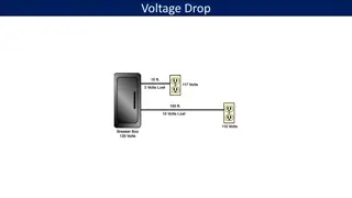
1) POWER ESTIMATION Metal wires that are required to carry too much power suffer metal migration, in which the atoms move within the wire, leaving a break in the conductor. Typical process rules specify the number of amps per unit width of wire. Standard IC packages can handle dissipations up to a few watts New packaging designs employ heat fins and other cooling methods to allow greater power dissipation. nMOS power consumption: (a) nMOS depletion transistor in pullup configuration (b) Pullup and pulldown. Coupling considerations in power estimation
2) Transistor-ratio checkers When doing VLSI layout, it is necessary to scale transistors so that they function effectively, relative to each other. In order to achieve proper logic transition, a threshold voltage must be crossed and the speed at which this happens is determined by the relative scales or ratios of the driving components. The problem is particularly important in nMOS design, because an imbalance exists between rising and falling transition times. To ensure that such a circuit will operate correctly, an analysis of the relative transistor ratios must be done. Restored and unrestored transistor ratios: (a) Restored (b) Unrestored
3) Short-circuits and isolated circuits A short-circuit is a path between any two unconnected nets such as from power to ground Detection of direct paths is simply a process of ensuring that the nets are distinct Often this is done during node extraction, when a simple test of the net numbers will tell the truth. Also important is a check to ensure that no transistor gates power and ground signals. Although this configuration is not a static short-circuit, it does not make electrical sense and is easy to detect Another static analysis is the detection of circuitry that is not properly connected Short-circuit configurations of power to ground.
4) Miscellaneous electrical rules There is an unending number of specialized electrical rules. When two output signals connect such that their values combine, they are called tied outputs. This may be purposeful, but it may also be an error. Microwave circuit boards require that the wires be tapered to prevent incorrect impedance conditions. Some design environments limit the number of components that an output signal can drive (fan-out limitation) or the number of input lines that a component can accept (fan- in limitation).
ERC Rules check for things such as Floating gates. Wrong transistor connections (Source and Drain connected together for instance). Floating interconnect, Metal, Poly Shorted Drain & Source of a MOS No substrate- or well contact ('figure having no stamped connection') Different contacts of substrate / well are connected to different nets Distance of MOS to next substrate / well contact too large (Latchup rule)


 MINIMUM WIDTH")
 Minimum spacing")
 Minimum enclosure")
 Minimum extension")

")

 POWER ESTIMATION")
 Transistor-ratio checkers")
 Short-circuits and isolated circuits")
 Miscellaneous electrical rules")