High-Speed Amplifiers: Design Techniques and Considerations
This detailed document explores the design aspects of high-speed amplifiers, focusing on transimpedance designs using high-speed op-amps. It covers basic and advanced design issues, frequency response analysis, and key considerations for achieving desired performance. The content emphasizes simplifications for accurate amplifier compensation methodology and debunks common misconceptions in transimpedance design. Practical examples, equations, and circuit analysis are provided to enhance understanding in this complex area of amplifier design.

Download Presentation

Please find below an Image/Link to download the presentation.
The content on the website is provided AS IS for your information and personal use only. It may not be sold, licensed, or shared on other websites without obtaining consent from the author.If you encounter any issues during the download, it is possible that the publisher has removed the file from their server.
You are allowed to download the files provided on this website for personal or commercial use, subject to the condition that they are used lawfully. All files are the property of their respective owners.
The content on the website is provided AS IS for your information and personal use only. It may not be sold, licensed, or shared on other websites without obtaining consent from the author.
E N D
Presentation Transcript
Texas Instruments High Speed Amplifiers Simple Transimpedance Designs Using High Speed Op Amps November, 2014 Michael Steffes/Xavier Ramus 1
Agenda Basic Issues Detailed Design equations Examples of Simple Design Advanced Transimpedance Designs Measuring Frequency response for Capacitive source circuits Detecting and amplifying the often very small current signal coming from a photodiode, can present a considerable challenge. The achievable gain, bandwidth, and input referred noise current are all coupled together in a few design variables. Most of this material comes from a series of articles referenced at the end where that material is also summarized in TI application note SBOA122. Many of the slides include more detail in the notes pages.
Design Issues Covered 1. Op Amp based, high performance, transimpedance designs can be analyzed using a single pole op-amp model to give a 2nd order closed loop transfer function. Although the full transfer function doesn t suggest a design approach, some judicious simplifications will lead to a very simple, and accurate, amplifier compensation methodology. 2. A simple equivalent input noise current equation, correctly including all of the high frequency terms (but neglecting 1/f effects), will allow an easy comparison between design solutions for their achievable sensitivity
Transimpedance Design (cont.) Numerous articles and discussion in the literature - several key misconceptions have complicated this application for many designers. Unity gain stability in the op amp is not required - a lot of literature suggests that it is. Feedback compensation is required even if a unity gain stable op amp is used. Many applications have an output noise spectrum dominated by the effect of the input noise voltage (not current) gained up to the output by the differentiator formed by the diode capacitance at the inverting node and the feedback resistor - this is often neglected. Putting the feedback pole at the intersection of the noise gain zero and the open loop gain curve is ideal? This is actually incorrect and yields a closed loop 2nd-order response with a Q 1 giving a step response that will overshoot and/or a frequency response that is peaking 1.25dB.
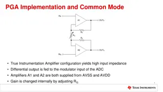
Transimpedance Frequency Response Analysis Circuit Deceptively simple looking circuit - that causes considerable difficulty in application. Cd is the diode capacitance plus wiring parasitic. Cs, used for design, is the total on the inverting node. + Cdiff A(s) VO - Ccm RF V- Id Cd -Vb CF VO = -V- A(s) Cs = Cd + Ccm +Cdiff
Controlling the Frequency Response Key variables required to determine Cf to get the desired frequency response 1. Total Capacitance on the Inverting node Be careful to include the op amp input parasitic capacitance. Cd is the detector diode capacitance under the expected reverse bias plus wiring parasitic. 2. Gain Bandwidth Product of the op amp The higher the gain bandwidth, the higher the resulting closed loop transimpedance bandwidth. In general, the op amp does NOT need to be unity gain stable. As will be shown, loop gain x-over typically occurs at a very high noise gain - so very wideband, non-unity gain stable, op amps can be used to get their lower input voltage noise. 3. Desired transimpedance gain or bandwidth These are interrelated - for a particular op amp selected, targeting the gain will set the maximum bandwidth or, conversely, targeting the bandwidth will set the maximum gain.
Full Laplace Transfer Function for the Transimpedance Op Amp Configuration A OL C A C ( ) + V R = O F s F R ( ) C F I + 1 C A ) D 2 + + + + F OL C A 1 1 s s A ( ( ) + A OL R C C + + C C R F s F s F s F F Where: ( ) A Transimpedance Gain = OL + A A s s A Single pole, open loop gain model 2 A = OL A Gain Bandwidth Product (GBP)
Standard O and Q form for this 2nd-Order Transfer Function. 2 V I A = O OL O R F + A 1 + + 2 2 s sQ O D OL O ( R ) C + + A 1 ( ) = = 2 OL A F ( ) O O C F S F ( R C F ) + A 1 OL A ( ) + + C S F = Q C + 1 + F 1 A ( ) A OL C C + R C F C S F S F
Loop Gain Analysis It is often instructive to look at the op amp circuit in loop gain form to view what each of the critical elements in the design mean graphically. The loop gain plot shows the open loop characteristic of the op amp with the noise gain superimposed - that gain starts out at 1 (0dB) then rises at Z1 with single zero response caused by the feedback resistor and inverting input capacitance (Cs) up to the pole formed by Rf and Cf. Several important points to note - 1. 2. FO is in fact the characteristic frequency of the closed loop response. Noise gain at x-over is 1+Cs/Cf which can be very high - hence, unity gain stability in the op am is not required.
Bode Plot of the Loop Gain for the Transimpedance Op Amp Configuration 1 = 20 log (AOL) Z Hz 1 + 2 C ( ) R 1 C Op Amp F s F Open Loop Gain 1= P Hz 2 R C Log Gain (dB) F F C + s 1 0= F Z GBP 1 20 log C f Noise Gain + 1 C = F GBP s C C F 0dB 1 Z 1P F F Gain Bandwidth Product (GBP) O C A 2 Log Frequency (Hz)
Analysis Simplifications Algebraic simplifications to get an easy compensation solution. 1. With Cs >> Cf, drop Cf from Z1 Equation Let (AOL + 1). a/2 = GBP (gain bandwidth product in Hz) This is simply neglecting the 1 2. 3. Drop the 1 in (1 + Aol(Cf/(Cs+Cf))
Simplified Expressions for Fo and Q = F Z GBP O 1 The 2nd-order characteristic frequency is fixed by - the Amplifier Gain Bandwidth Product - and the zero formed by the transimpedance gain resistor and the source capacitance F P = = O Q 1 Fc F O The Q of the 2nd-order closed-loop transfer-function is simply the ratio of the pole frequency set in the feedback path to the characteristic frequency (P1/FO) which is also equal to the ratio of the characteristic frequency to the intersection of the open loop response. with the high frequency noise gain (1+Cs/Cf) - this is FO/Fc.
Design Methodology The next slide steps through finding the maximum available transimpedance gain for a given op amp and diode if a maximally flat Butterworth response is the target design. This target is interesting in that if we set P1 at 0.707*FO, it circles back to give us a F-3dB equal to FO. Kind of unique and interesting design point. More general targets with peaking can be designed using the initial equations. A very useful alternative way to use these equations is to know your desired transimpedance gain and bandwidth and use them to solve for the minimum required GBP. Then the compensation capacitor (Cf) can be calculated using an amplifier with a GBP > than that minimum, along with this target transimpedance gain. The calculation for Cf is shown on the next slide.
Design Simplifications If a target of Q = 0.707 is set, a very simple design methodology results. At Q = 0.707, the 2nd-order closed-loop response gives an F-3dB = FO So, if we set P1 = 0.707*FO, we get an F-3dB = FO Assuming this - and then targeting an F-3dB, sets the FO target in a design. Z F F O dB 3 = = ( ) dB GBP 2 GBP 1 (With Q = 0.707) 2 1 F = = 3 Z 1 R C F s C GBP , F3 Maximum achievable gain given ,and target s dB GBP = R ( ) F 2 2 F C 3 dB s
Simplified Design Continued With maximum achievable gain (RF) set, can go back and set Cf to put P1 where it needs to be for Q = 0.707 1 = = = . 0 707 . 0 707 P F F 1 3 O dB 2 R C F f 1 = C ( . 0 ) F 707 2 R F 3 F dB
Total Equivalent Input Current Noise Calculation The total input referred current noise equation that often appears in the High Speed Amplifier group de-compensated voltage feedback op amps uses several simplifying assumptions to arrive an approximate expression. Specifically - 1. This is an integrated noise analysis that uses spot noise over frequency - not intended as a spot noise equation for narrowband applications. 2. We are assuming the application is DC-coupled, pulse oriented where the integrated noise is of interest. 3. The final signal bandwidth for both the transimpedance design and any post-filtering is >10X the 1/f noise corner for any of the op amp noise terms - this allows those effects to be neglected for integrated noise purposes 4. While the amplifier must be compensated with a feedback capacitor, it is much simpler for noise calculation purposes to assume a noise power bandwidth lower than this that will be set further downstream in the signal path. This means the target transimpedance bandwidth should be set > than the bandwidth that will be set by post-filtering.
Total Input-Referred Equivalent Input- Noise Current for Wideband Transimpedance Design ( ) 2 2 FC 4 2 kT e e 2 = + + + n n s EQ i i b 3 R R F F
Simplified Transimpedance Noise Analysis A thorough expression for transimpedance output noise can be extremely complicated This principally arises from two issues 1. Including 1/f effects in the analysis - neglecting those for broadband applications creates a slight error but considerable simplicity. 2. Allowing each noise term to be combined at the output with a frequency response set only by the transimpedance amplifier design itself. If we assume the transimpedance stage is designed to provide > than the desired final signal bandwidth, a post-filter downstream can be assumed for noise power bandwidth limiting purposes. That frequency F can then be used to calculate integrated noise.
Input Noise Terms The input noise terms needed for a transimpedance design are shown on the next slide. These include 1. Non-inverting input voltage noise (en - this will have a gain to the output of 1 at DC then increasing at 20dB/decade beyond (1/2 RfCs)Hz which is the zero frequency (Z1) in the noise gain. 2. Inverting input current noise (ibi) 3. Feedback resistor noise voltage = (4kTRf) These last two terms will, strictly speaking, have a response pole to the output set by P1. Since we will be assuming a post-filter below P1, we will neglect this internal band-limit and just apply an integration frequency of F to all the noise terms.
Transimpedance Noise Analysis Circuit + ne oe Voltage Feedback Op Amp - bi C f R 4 kTRf s
Gain for the Noise Terms to the Output The resistor voltage noise shows up directly at the output with no gain. Square that to get noise power The amplifier s inverting input current noise shows up at the output times the feedback resistor. Square that to get the noise power The amplifier s input voltage noise has a gain to the output that traces out the noise gain curve shown earlier in the Bode analysis. Only the zero is considered here since we will assume a frequency of integration that is less than the pole and set by a post-filter. Again, square this output noise voltage term to get power.
Total output noise power To get the total output noise power, take each noise term times its gain to the output, square it, then add. Note that this circuit does not show a feedback capacitor - that capacitor (Cf) is absolutely required for stability but is not shown here since the noise integration frequency is assumed to be less than the pole set by (1/2 RfCf)Hz = P1 2 2 2 2 = + + 2 ( + 4 ( ) 1 [ ) ] e kTR i R e fC R o f b f n s f
Input-Referred Equivalent Input Noise Current 2 f R Input refer eo2 by dividing by 2 4 e kT 2 2 2 = + + + 2 2 ( ) n i i e f Cs eq b n 2 R R f f Frequency dependent term
Getting an average value for the last term. The final term in the total input-referred noise-current expression increases with frequency - this is the differentiated input noise voltage of the op amp that will appear at the output. To get an average equivalent value, this must be integrated over F then divided by F. Strictly speaking, a starting integration value of 0Hz is not physically correct - but can be used as a simplification. For f = 0 F Average the noise power of the 4th term over the noise power bandwidth - F F 2 2 3 ( 2 ) ( 2 ) 1 F e C e C F f F = = 2 ( 2 ) n s n s e f Cs df n 3 3 F 0 0
Input Referred equivalent input noise current This average value over F for the last term may now be combined with the other 3 terms that have no frequency dependence to get the total equivalent input referred current noise expression. This input referred spot noise current will integrate to the same total output noise power as the actual output noise spectrum if the frequency span of integration is limited to F . This expression is what shows up in the data sheets. ( ) 2 2 2 4 e e F C kT 2 = + + + n n s i i EQ b 3 R R F F
Equivalent Input Spot Current Noise for Output Noise Integrated to F < P1 ( ) 2 2 2 4 e e F C kT 2 = + + + n n s i i EQ b 3 R R F F Where: bi = Inverting input spot current noise for the op amp 4kT = 16 10 R = the feedback resistor value ne = Non-inverting input spot voltage noise for the op amp C = Total capacitance on the inverting node of the op amp F = Frequency limit of noise integration ( P1) 21 J at 290K F s
Design Examples - Getting a Target Bandwidth Given a Source Capacitance 1. Select an Op Amp with a particular GBP - include its input parasitic capacitance + the source diode capacitance to solve for Z1 given the desired bandwidth and actual GBP. With Z1 set, solve for achievable maximum gain, = Rf to get the minimum input referred noise current. 2. Set P1 at Q * FO. Use this and Rf to solve for Cf. 3. Check that 1 + Cs/Cf > minimum stable gain for the op amp selected
Wideband VFB Op Amps Suitable for Transimpedance design VOLTAGE FEEDBACK AMPLIFIERS SUITABLE FOR TRANSIMPEDANCE APPLICATIONS THIS IS LIMITED TO GBP > THAN 200MHz Part # Input Type GainBandwidth Minimum StableInput Voltage Input Current Min. Supply Max. Supply Supply Product(MHz) Gain (V/V) Noise (nV) Multi-Channel Noise (pA) Voltage Voltage Current(mA) Versions OPA820 OPA690 OPA842 OPA843 OPA846 OPA847 OPA656 OPA657 THS4021 Bipolar THS4031 Bipolar OPA355 Bipolar Bipolar Bipolar Bipolar Bipolar Bipolar JFET JFET 240 300 200 800 1750 3900 230 1600 1400 200 200 1 1 1 3 7 12 1 4 7 1 1 2.4 5.5 2.6 2 1.2 0.85 7 4.8 1.5 1.6 4 1.6 3.1 2.7 2.8 2.8 2.5 0.002 0.002 2 1.2 0.002 5 5 7 7 7 7 7 7 12.6 12.6 12.6 12.6 12.6 12.6 12.6 12.6 5.6 5.5 20.2 20.2 12.6 18.1 14 14 8.1 8.5 8.3 Quad Dual,Triple Dual Dual Dual CMOS Dual,Triple
Example Design #1, 20Mhz from 20pF In this case we are starting with a source capacitance a target bandwidth and an amplifier and seeing how high a transimpedance gain we can get, then we compute the input-referred noise, integrating through P1. OPA846 WIDEBAND, LOW NOISE, OP AMP $1.59/(in thousands) Gain Bandwidth Product (non-unity gain stable) Non-inverting Input Voltage Noise Inverting Current Noise (Bipolar Input) Common-mode parasitic Input Capacitance Differential parasitic Input Capacitance 1750MHz 1.2nV/root Hz 2.8pA/root Hz 1.8pF 2.0pF Diode source Capacitance Desired Butterworth (Q=.707) Bandwidth Maximum allowed Rf to get Bandwidth Required Cf High Frequency Noise Gain (1 + Cs/Cf) Equivalent Input Current Noise Density (integrated to P1= .707*20MHz) Equivalent Input Integrated Noise (IRMS = IEQ*?P1) 20pF 20MHz 27.6kohm 0.41pF 59V/V 3.3pA/?Hz 12nARMS
Example Design Using a Wideband Bipolar Input Op Amp. +5v + vo OPA846 - -5V OPA846 Frequency Response 27.6k 92 89 iD Gain (dB) 20pF 86 0.41pF -VB 83 80 1.E+06 1.E+07 1.E+08 Frequency (Hz)
Example Design #2, 2Mhz from 200pF In this case we are starting with a source capacitance a target bandwidth and an amplifier and seeing how high a transimpedance gain we can get then computing the input-referred noise, integrating through P1. Here we select a JFET device as the Rf will be too high for a bipolar input bias current OPA657 SPECIFICATION AND DESIGN $3.59/(in thousands) Gain Bandwidth Product (non-unity gain stable) Non-inverting Input Voltage Noise Inverting Current Noise (Bipolar Input) Common-mode parasitic Input Capacitance Differential parasitic Input Capacitance 1600MHz 4.8nV/?Hz 1.3fA/?Hz 4.5pF 0.7pF Diode source Capacitance Desired Butterworth (Q=.707) Bandwidth Maximum allowed Rf to get Bandwidth Required Cf High frequency noise gain (1 + Cs/Cf) Equivalent Input Current Noise Density (integrated to P1= .707*2MHz) Equivalent Input Integrated Current Noise (IRMS = IEQ*?P1) 200pF 2MHz 310kohm 0.36pF 380V/V 5pA/?Hz 6nARMS
Example Design Using a Wideband JFET Input Op Amp +5v + vo OPA657 - -5V OPA657 Frequency Response 310k 113 iD 200pF 110 Gain (dB) 0.36pF -VB 107 104 101 1.E+05 1.E+06 1.E+07 Frequency (Hz)
Design Discussion The OPA657 design yielded 5pA equivalent input noise current if we assume a noise power bandwidth limit set to 1.4Mhz. This is totally dominated by the 3rd-term of the total noise equation the effect of the rising portion of the noise gain curve times the relatively high 4.8nV input voltage noise for the OPA657. Repeating this design using the OPA846, with its much lower voltage noise but much higher current noise, actually yielding a lower equivalent input noise current. Specifically, the OPA846 will give the same bandwidth and an input noise of 3pA vs. 5pA for the OPA657. So why don t we use the OPA846??
High Gain Design Repeated with the OPA846 High common mode voltage +5V + .01mF 310k 19mA Ib OPA846 - -5V 300k 200pF 0.36pF -Vb
OPA846 Options at 310k If we look at the effect of the OPA846 s 19mA input bias current using a 310k feedback, we would see a 5.89V output-offset voltage. Adding a 310k resistor on the non-inverting input will allow bias current cancellation, but will now put a 5.89V common mode voltage on the inputs which is out-of-range for a +/-5V operation. There is a way around this - The T-feedback structure has the interesting effect of also reducing the required input-matching resistor to get bias-current cancellation. This can be used to bring the input common mode voltage into range. Whenever this bias current cancellation is used for a transimpedance design, it is imperative to decouple that resistor to kill its noise contribution.
Adapting a Transimpedance Design to the T-Feedback structure Essentially, we implement an equivalent feedback impedance with an initial resistor out of the summing junction towards the output then implement a voltage divider that will have the effect of gaining up that impedance. From an initial single resistor design, decide how much voltage divider gain you want, divide the original resistor by that value and multiply the compensation capacitor by that value. The 310k design is adapted to the OPA846 by using a gain of 10V/V resistor divider this will reduce the required bias current cancellation resistor to 31k significantly reducing the common-mode voltage generated by the input bias current. That new circuit is shown on the next slide.
High Gain Design Repeated with the OPA846 Modified to the T-network in the feedback Much lower common mode voltage +5V + 25C max VOS = 10 ( 0.6mV) 310k .35mA = 115mV Vio 0.1mF 31k 19mA Ib OPA846 IOS - -5V 31k 900 200pF 100 3.6pF -Vb This approach does work, but will have much higher output-offset voltage than the OPA657.
Modified OPA846 Transimpedance Frequency Response OPA846 310kohm using T-network 120 110 100 Gain (dB) 90 80 70 60 50 40 1.0E+04 1.0E+05 1.0E+06 1.0E+07 1.0E+08 Frequency (Hz) This also simulated out to approximately 3pA input-referred current-noise if F = 1.4MHz
Increasing Performance of a Transimpedance Design. If the required design does not reach the needed gain or bandwidth for a given detector capacitance, one way to improve performance without impacting noise too much is to use an imbedded gain stage. Adding a wideband gain stage inside the loop increases the gain-bandwidth product directly. This allows either the bandwidth for a targeted gain to be increased or the gain for a targeted bandwidth to be increased at a square-root rate. For instance, adding a gain of 4 inside the loop will give the option of either a doubled gain or bandwidth.
Embedded Gain Transimpedance Design + A(S) + - Rg1 - R Rf1 1 f = + 1 A V R 1 g Rf Cs Cf -Vb Use Av *GBP to work through this design.
Using a Network Analyzer to Test a Transimpedance Amplifier Design Often, the actual diode and its response is not well known. It is very useful to be able to separately test the AC performance of a proposed design. This can be done using a network analyzer where it feeds first into a 50ohm series resistor and then into a capacitive divider. At higher frequencies, the capacitors short out and the network analyzer see its desired 50ohm termination. The caps. Act like a current divider sending a small portion of the current through the series 50ohm into the series cap that connects to the circuit under test. The apparent source impedance looking back into the circuit becomes the series capacitor at high frequency
Using a Network Analyzer to Test a Transimpedance Amplifier Design Network analyzer source RS C2 RS To transimpedance stage 50 50 Id Test current C1 VS
Added Transimpedance Design Resources 1. Control Frequency Response and Noise in Broadband, Photo detector Transimpedance Amplifiers Michael Steffes EDN, Design Feature - July 4th, 1996 pp113-125 2. Embedded gain supercharges FET- transimpedance amplifier . Michael Steffes EDN, Design Feature May 22nd, 1997 pp129-142 3. Here s an Easy Way to Test Wideband Transimpedance Amplifiers . Michael Steffes Electronic Design, Analog Application Issue - June 8th, 1998 pp74-80 Transimpedance Considerations for High-Speed Operational Amplifiers . Xavier Ramus http://focus.ti.com/general/docs/litabsmultiplefilelist.tsp?literatureNumber=sboa122 High Speed Amplifiers offering from Texas Instruments that include a transimpedance design discussion and greater than 1.5GHz GBP. OPA657, JFET Input, 1600MHz Gain Bandwidth OPA846, Gain of 7 stable, 1750MHz Gain Bandwidth OPA2846 dual, gain of 7 stable, 1750 MHz GBP OPA847, Gain of 12 stable, 3900MHz Gain Bandwidth
Conclusions for Transimpedance Compensation and Noise Analysis 1. The closed loop response is a 2nd order low pass, where: 1. The characteristic frequency is always the geometric mean of the zero in the noise gain and the op amp s gain bandwidth product. 2. Placing the feedback pole only changes the Q of the response. Setting P1 = 0.707 * FO will give a closed loop Butterworth response with F-3dB = FO Since the noise gain always crosses over the open loop gain at a high value if compensated correctly, the op amp does not need to be unity gain stable. The output noise can be strongly influenced by the peaked up voltage noise term. Generally, Bipolar Inputs are better for low to moderate gains at wider bandwidths while JFET inputs are better for high transimpedance gains at lower bandwidths. With Bipolar inputs, a resistor equal to Rf is placed to ground on the non- inverting input to improve DC accuracy - this must be bypassed with a capacitor to kill its noise contribution. If high Rf are needed on a bipolar solution, consider the T-network approach to keep the common mode voltages in range. 2. 3. 4. 5. 6.


")