Understanding High Power Amplifiers with BJT for Efficient Performance
Explore the world of high-power amplifiers utilizing BJT technology, focusing on factors like linearity, efficiency, and maximum power capability. Learn about different amplifier classes - A, B, AB, and C - each with unique operating characteristics. Discover the significance of amplifier efficiency in optimizing power utilization.

Download Presentation

Please find below an Image/Link to download the presentation.
The content on the website is provided AS IS for your information and personal use only. It may not be sold, licensed, or shared on other websites without obtaining consent from the author. Download presentation by click this link. If you encounter any issues during the download, it is possible that the publisher has removed the file from their server.
E N D
Presentation Transcript
Unit II High Power Amplifiers -18marks
Course Outcome Use BJT as high power amplifier
Definitions In small-signal amplifiers the main factorsare: Amplification Linearity Gain Since large-signal, or power, amplifiers handle relativelylarge voltage signals and current levels, the main factorsare: Efficiency Maximum powercapability Impedance matching to the outputdevice 3
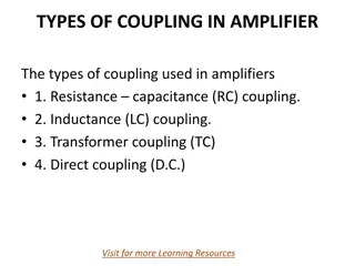
AmplifierTypes ClassA The amplifier conducts through the full 360 of the input. The Q-point is set near the middle of the loadline. Class B The amplifier conducts through 180 of the input. The Q-point is setat the cutoffpoint. ClassAB This is a compromise between the class A and B amplifiers. The amplifier conducts somewhere between 180 and 360 . The Q-pointis located between the mid-point andcutoff. 4
AmplifierTypes Class C The amplifier conducts less than 180 of the input. The Q-point is located below the cutofflevel. 5
Class AAmplifier The output of a class Aamplifier conducts for the full 360 of the cycle. The Q-point is set at the middle of the load line so that the AC signal can swing a full cycle. Remember that the DC load line indicates the maximum andminimum limits set by the DC powersupply. 6
Class BAmplifier A class B amplifieroutput only conducts for 180 or one-half of the AC input signal. The Q-point is at 0V on the load line, so that the AC signal can only swing for one-half cycle. 7
Class ABAmplifier This amplifier is a compromise betweenthe class A and class B amplifier the Q-point is above that of the Class B but below the classA. The output conducts between 180 and 360 of the AC inputsignal. 8
Class C The output of the class C conducts for less than 180 of the AC cycle. The Q-point is below cutoff. 9
Amplifier Efficiency Efficiency refers to the ratio of output to input power. The lower the amount of conduction of the amplifier the higher the efficiency. 10
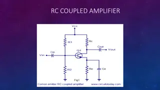
Direct Coupled Class-A Amplifier This is similar to the small-signal amplifier except that it willhandle higher voltages. The transistor used is ahigh- powertransistor. 11
Direct Coupled Class-A Amplifier When an input signal is applied the output will vary from its dc bias operating voltage and current. A small input signal causes theoutput voltage to swing to a maximum of Vcc and a minimum of 0V. The current can also swing from 0mA to ICSAT (VCC/RC) 12
Direct Coupled Class-A Amplifier Input Power The power into the amplifier is from the DC supply. With no input signal, the DC current drawn is the collector bias current, ICQ. Pi(dc) = =VCCICQ OutputPower V2C(rms) CE(rms) C(rms) = V o(dc) P I or Po(ac)= R C Po(dc)= I2C(rms)Rc Efficiency Po(ac) % = = 100 Pi(ac) 13
Transformer-Coupled Class AAmplifier This circuit uses a transformer to couple to the load. This improves the efficiency of theClass A to50%. 14
TransformerAction A transformer improves the efficiency because it is able to transform the voltage, current, and impedance Voltage Ratio V2 = =N2 V1 N1 Current Ratio I 2 =N1 I1 N2 Impedance Ratio N1 2 = = N R1 R L 2 = = = = a R R 2 2 L 15
Transformer-Coupled Class AAmplifier DC Load Line As in all class A amplifiers the Q- point is established close to the midpoint of the DC load line. The dc resistance is small ideally at0 and a dc load line is a straight vertical line. AC Load Line The saturation point (ICmax) is at Vcc/R L and the cutoff point is at V2 (the secondary voltage of the transformer). This increases the maximum output swing because the minimum and maximum values of IC and VCE arespread furtherapart. 16
Transformer-Coupled Class AAmplifier Signal Swing and Output ACPower The voltage swing: VCE(p p) = = VCEmax VCEmin The current swing: Ic( p p)= IC max IC min The ACpower: Po(ac)=(VCEmax VCEmin )(ICmax ICmin )(maximum) 8 17
Transformer-Coupled Class AAmplifier Efficiency Power input from the DC source: Pi(dc) = =VCCICQ Power dissipated as heat across the transistor: Note: The larger the input and output signal,the lower the heatdissipation. PQ = = Pi(dc) Po(ac) Maximumefficiency: VCEmax VCEmin 2 % = = 50 Note: The larger VCEmax and smaller VCEmin, the closer the efficiency approaches the theoretical maximum of 50%. CEmax+ V V CEmin 18
Crossover Distortion If the transistors Q1 and Q2 do not turn on and off at exactly the same time, then there is a gap in the outputvoltage. 19
Class CAmplifiers A class C amplifier conducts forless than 180 . In order to produce afull sine wave output, the class C uses a tuned circuit (LC tank) to provide the full AC sinewave. Class C amplifiers are used extensively in radiocommunications circuits. 22