eClutch Diagnostic Flowchart for DCD991/DCD996 Drill
This detailed eClutch diagnostic flowchart provides step-by-step instructions for troubleshooting potential customer complaints related to the functionality of the DCD991/DCD996 drill, focusing on clutch modes, motor responses, and sensor checks. It covers functional checks, electrical checks, and electro-mechanical checks to pinpoint the root cause of issues before disassembly, ensuring the drill is operating correctly.

Download Presentation

Please find below an Image/Link to download the presentation.
The content on the website is provided AS IS for your information and personal use only. It may not be sold, licensed, or shared on other websites without obtaining consent from the author. Download presentation by click this link. If you encounter any issues during the download, it is possible that the publisher has removed the file from their server.
E N D
Presentation Transcript
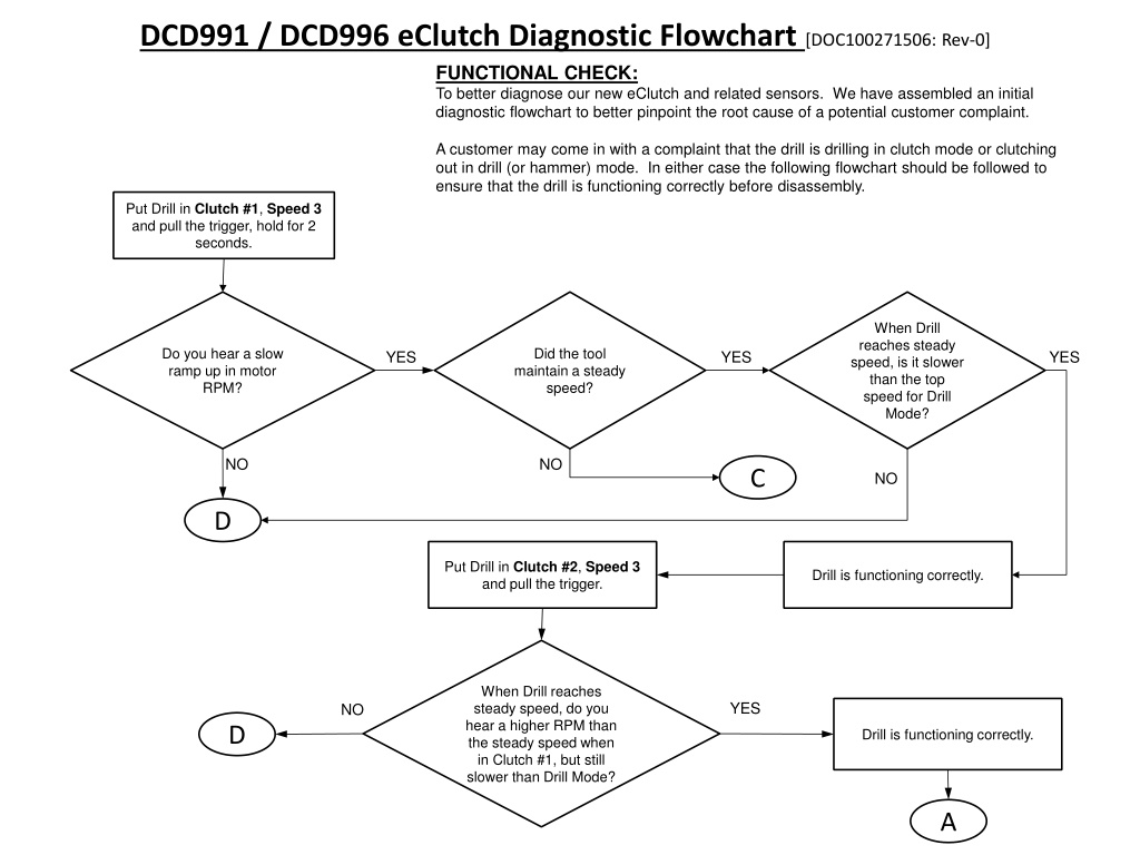
DCD991 / DCD996 eClutch Diagnostic Flowchart [DOC100271506: Rev-0] FUNCTIONAL CHECK: To better diagnose our new eClutch and related sensors. We have assembled an initial diagnostic flowchart to better pinpoint the root cause of a potential customer complaint. A customer may come in with a complaint that the drill is drilling in clutch mode or clutching out in drill (or hammer) mode. In either case the following flowchart should be followed to ensure that the drill is functioning correctly before disassembly. Put Drill in Clutch #1, Speed 3 and pull the trigger, hold for 2 seconds. When Drill reaches steady speed, is it slower than the top speed for Drill Mode? Do you hear a slow ramp up in motor RPM? Did the tool maintain a steady speed? YES YES YES NO NO C NO D Put Drill in Clutch #2, Speed 3 and pull the trigger. Drill is functioning correctly. When Drill reaches steady speed, do you hear a higher RPM than the steady speed when in Clutch #1, but still slower than Drill Mode? YES NO D Drill is functioning correctly. A
A Put Drill in Clutch #11, Speed 3 and pull the trigger. When Drill reaches top speed, do you hear a similar speed as Drill Mode? Do you hear the tool reach steady speed faster than when in clutch #2? NO YES YES D NO D Put Drill in DRILL MODE, Speed 3 and pull the trigger. Drill is functioning correctly. Is the motor response immediate (e.g. no ramp up) when you pull the trigger? YES NO D Drill is functioning correctly. FIRMLY grab chuck wearing leather work gloves and pull trigger. Put Drill back into Clutch #1, Speed 3. B
B NO YES Does Drill clutch out immediately? Release hand from Chuck. Drill is functioning correctly. D C C Did the unit reach and sustain a top speed 8 out of the 10 times? Put Drill in Clutch #1, Speed 3 and pull the trigger 10 times for 2 seconds each time. (Do not hold the chuck.) Drill is functional. (Return to top of diagnostics if not already completed) YES NO Replace Tool Replace transmission SA s #19, #20, and ring gear #16 NO YES Did you already replace the transmission SA s? Replace transmission SA s #19, #20, and ring gear #16 Replace Tool C
ELECTRICAL CHECK: Remove housing and gearcase screws, opening up and removing cover side handle. Carefully remove Transmission Front End and Module/Motor together as one full unit. D Inspect all wires for pinches, nicks, or cuts. Anything abnormal can effect function. While on ESD mat with grounding wrist strap; pull motor out of transmission. While on ESD mat with grounding wrist strap; pull motor out of transmission. This next step is to interrogate the electrical inputs and outputs from Clutch Position Sensor (CPS) Disconnect Clutch Position Sensor (CPS) from Switch Module. Make sure the pins were seated in the connector and not installed under it. Clutch Setting 1% #1 2000 Put Clutch Collar in Clutch Setting #1 #2 4000 #3 5870 #4 7740 #5 9790 With multi-meter, probe the 2 pins of the CPS connector. #6 12600 #7 16400 #8 21040 #9 27380 Is the value within the range given in the table? #10 37140 NO #11 50140 DRILL 72240 HAMMER 106240 YES Repeat for all Clutch Settings (#2 to #11), DRILL MODE and HAMMER MODE. E
ELECTRO-MECHANICAL CHECK: Further disassembly is not required. E Visually inspect Clutch Position Sensor (CPS) wires Reassemble Front End Replace Module (Item# 34) Reassemble Front End NO Are all wires, connections and connector pins/bodies from module intact? Are all wires, connections and connector pins/bodies from module intact? Are all wires, and connector pins/bodies in good condition? YES NO YES Replace Service SA Gear Case (HD: Item#1-11) (DD: Item#1, 6-11)
Power Wire (RED) Ground Wire (BLK) LED on indicates power to Sensor
Occasionally the pins will get bent down and slide under the mating connector instead of into. Inspect units for this, and be sure not to do this. Connector pins should be pushed fully into connector body.


")