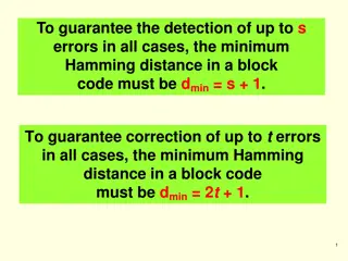
PC Troubleshooting: Tools, Post of Pentium, and Beep Codes
Understanding PC troubleshooting methods using hardware and software tools, Post of Pentium test sequence, and interpreting beep codes for IBM PCs. Learn about diagnosing and resolving PC hardware issues efficiently.

Download Presentation

Please find below an Image/Link to download the presentation.
The content on the website is provided AS IS for your information and personal use only. It may not be sold, licensed, or shared on other websites without obtaining consent from the author. Download presentation by click this link. If you encounter any issues during the download, it is possible that the publisher has removed the file from their server.
E N D
Presentation Transcript
Chapter 7 : PC Troubleshooting, Maintenance and Tools Visit for more Learning Resources
Troubleshooting : Verifying a real problem, analyzing symptoms and isolating and correcting a failure in the PC are called troubleshooting. Hardware Tools are used for this purpose are logic probe, logic pulser, current tracer, logic analyzer,BIOS POST card etc Software Tools are used for this purpose are advance diagnostic software, Norton Utility, PC tools, QA plus, etc Test Points- for eg. Printer have indicator lights which change colors or blink
POST of Pentium : Collection of test program Automatically executed by the PC whenever the PC is started Is stored in ROM BIOS on motherboard Microprocessor start instruction processing from the memory address FFFF0 H from where the POST being Is series of simple programs design to test and catch faults If the test successful, the POST arranges for loading the operating system from a diskette If any hardware error is noticed, the POST indicates. The fault to user in four differen ways : 1.Check points 2.Beeps 3.Error code displays 4.Detailed error message
The sequences of tests in POST are as given below. 1.Determine density and type of SIMMs 2.Shadow system BIOS(System BIOS on the flash is copied to main memory) 3.Initialize interrupt controllers and chip sets 4.CPU test 5.Size L2 cache 6.Test CMOS 7.Test and initialize CMOS 8.Test DMA 9.Verify if refresh is running 10.Test base 64K of memory 11.Determine total memory size 12.Initialize keyboard controller 13.Detect presence of external Video controllers 14.Configure PCI video, set monitor refresh rates and size video memory 15.Display banner 16.Reset keyboard 17.Test memory above 64 K, base and extended 18.Flush and enable L2 cache 19.Initialize serial and parallel port controllers 20.Initialize floppy controller and seek for floppy drives specified in the CMOS 21.Reset mouse 22.Initialize hard disk subsystem. Determine type and size of IDE drives
23.Run plug and play code 24. Beep signifying end of POST 25. Boot to OS on bootable media
Beep Codes For IBM PCs Beep Code No Beeps 1 Short Beep 2 Short Beep Continuous Beep Repeating Short Beep One Long and one Short Beep One Long and Two Short Beeps One Long and Three Short Beeps. Three Long Beeps One Beep, Blank or Incorrect Display Description No Power, Loose Card, or Short. Normal POST, computer is ok. POST error, review screen for error code. No Power, Loose Card, or Short. No Power, Loose Card, or Short. Motherboard issue. Video (Mono/CGA Display Circuitry) issue Video (EGA) Display Circuitry. Keyboard or Keyboard card error. Video Display Circuitry.
For AMIBIOS Beep Code 1 short 2 short 3 short 4 short 5 short 6 short 1 long, 3 short 1 long, 8 short two-tone siren Descriptions DRAM refresh failure Parity circuit failure Base 64K RAM failure System timer failure Process failure Keyboard controller Gate A20 error Conventional/Extended memory failure Display/Retrace test failed Low CPU Fan speed, Voltage Level issue Visual Display Codes : The POST display some codes on the monitor, that codes called as visual diplay codes.
Preventive Maintenance of Peripheral of PC : Two Type of Maintenance Active and Passive It describes several procedures to clean and lubricate all the major components, cleaning all boards, connectors, contacts etc. It also describes similar procedures for different peripheral devices such as HDD, FDD, keyboard, printer, monitor etc. It includes performing backups, antivirus and antispyware scans.
Active preventive maintenance includes i)Regular cleaning of the system using cleaning tools & cleaning solutions ii) Preventive maintenance of the system, which are either weekly or monthly. Weekly maintenance includes Backup of important data Deleting temporary files Empty recycle bin Check for antivirus software updates Run defragmentation program Monthly maintenance includes, Create a startup disk Check for updated drivers O.S. updates Cleaning the drivers
Passive prventive maintenance It involves taking care of the system from physical environment and electrical problems. Physical conditions such as temperature, thermal stress, dust and smoke contamination and shock and vibration. Electrical issues such as ESD (Electro Static Discharge), power line noise and RFI (Radio frequency interference) Physical contributors to system failure 1. Dust and pollutants The power supply fan carries air borne particles through your system and they collect inside the system. Prevention of dust and dirt Use dust covers when not in use. Use curtains on windows Use air conditioners for computer room. Avoid shoes into computer room. Avoid smoking near a PC. Use vacuum cleaner to clean the surrounding area of the PC frequently.
2. Excessive temperature Thermal expansion and contraction from excessive temperature changes places thermal stress on the system. To avoid this temperature in the room must remain relatively constant. There are two conditions of excessive temperature: Heat and Cold Excessive heat leads to Breaking of solder joints. Damage of solid state components. Accelerated corrosion of contacts in the system Cracking of circuit boards. Problems with hard disk as the metallic components expand. Prevention Keep the cooling vents clear. Keep the system dust free from inside and outside. Keep the disks in cool dry location. Install air conditioners to maintain the room temperature. Effect of Cold Due to cold the resistance of electronic components decreases and the component will take very large current when the system is switched on. Low temperatures affect the mechanical components of the FDD. The floppy disk becomes brittle. Prevention Use room heater to maintain the room temperature.
3. Corrosion It is a chemical process in which metal coating of pins and sockets is gradually oxidized. Corrosion Effects Types Direct oxidation: In this a film of oxide is formed on the metal surface. The metal film acts as an insulator and creates contact problems. Atmospheric corrosion: It causes rusting and reduces the electrical contact between the components. Galvanic corrosion: Moisture borne electrolyte enters through a tiny crack or hole in the metal plating and causes corrosion. Prevention Periodic cleaning. Clean the pins of ICs and connectors. Use organic solvent for cleaning the oxide layer and corroded contacts.
4. Magnetic Effect Magnets both permanent and electromagnetic type can cause permanent loss of data on the hard disk. In office electromagnetism can be produced by electric motors. The voltages used in monitor and television receiver are sources of strong magnetic fields. Other sources of magnetism: Paper clip holder with a magnet, stereo speakers, Magnetic screw extractor, metal detectors etc Prevention To avoid data loss due to magnetism, keep disks and information cables away from the magnets.
Electrical contributors to system failure 1.ESD (Electro Static Discharge) This problem usually arises in winter when the humidity is low. Our body can accumulate static charges up to 25,000V. When we touch any component in the PC the accumulated static charge will discharge to ground. This can damage the component. Prevention Before touching any component we must discharge any accumulated potential to ground. This can be done by touching the ground area of the system. Use ground strap attached around your wrist. The other end of the strap is connected to the system ground. Use anti static mat Do not wear synthetic clothes. The system should have good power line grounding.
2. Power line noise A computer system should have steady supply of noise free power. The circuit should be checked for good low resistance ground, proper line voltage, free from interference and brownouts. Three pin socket is a must. Power line noise problem increases with wire size and length. Prevention Isolation, Shielding, Power grounding. 3. Radio Frequency interference (RFI) It is caused by any source of radio transmission near a PC. It is high frequency radiation (freq > 10 Khz). Sources of RFI High speed digital Circuits, nearby radio source, Cordless telephones, Mobile phones, motors, Power line intercoms. Prevention Put all the sources which can produce RFI away from the PC.
A logic analyzer is an electronic instrument that displays signals in a digital circuit that are too fast to be observed and presents it to a user so that the user can more easily check correct operation of the digital system. Fig. shows functional block diagram of logic analyzer. A logic analyzer is a device, which allows you to see the signals on 16 to 64 signal lines at once. It is also called multi-trace digital oscilloscope. It captures and stores several digital signals, letting you view the signals simultaneously
Working: 1.All the input signals are applied to the adjustable threshold comparator one for each channel. 2.Then reference input for each signal can be adjustable depending on logical state of device under testing. 3.The logic analyzer takes sample of each input signal from comparator whenever clock signal is applied to memory and to stores into memory. 4.The clock input may be from : 5.o Internal asynchronous clock input: It produced by internal oscillator, which is very stable in operation. 6.o External clock input: It is clock from any external source. It takes around 256 to 1024 samples of each signal and stores them in memory. 7.When trigger is applied to memory, memory displays these stared samples. 8.The trigger input may be from Word comparator or External trigger input. 9.o The word comparator generates trigger when it's two input one from adjustable threshold comparator and another from word selection switch. If both inputs code are same then it send trigger to memory. 10.After applying trigger to memory, then it send to display scan circuit. 11.The display scan circuit then constructs the original waveform and displays it on the CRT
Logic Probe: - A logic probe is able to give an indication of the logic state of a line carrying a digital signal. The logic probe indicates whether there is a logic state "1" or "0", normally using an LED as the indicator. Often the LED on the logic probe will use different colors to indicate different states. A logic probe normally may be capable of indicating up to four different states: For more detail contact us