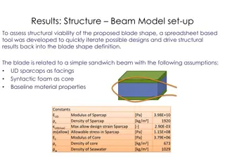
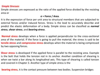
Understanding Beam Elements and Shear Effects in Structural Analysis

Beam elements play a crucial role in structural analysis, offering insights into line elements with various degrees of freedom for bending modes and stress analysis. Shear deflection and stresses in beams are essential considerations when accounting for shear effects. Learn about real constants, shape functions, ANSYS beam element types, and more in this comprehensive guide.

Download Presentation

Please find below an Image/Link to download the presentation.
The content on the website is provided AS IS for your information and personal use only. It may not be sold, licensed, or shared on other websites without obtaining consent from the author. Download presentation by click this link. If you encounter any issues during the download, it is possible that the publisher has removed the file from their server.
E N D
Presentation Transcript
Beam Elements Jake Blanchard Spring 2008
Beam Elements These are Line Elements, with 2 nodes 6 DOF per node (3 translations and 3 rotations) Bending modes are included (along with torsion, tension, and compression) (there also are 2-D beam elements with 3 DOF/node 2 translations and 1 rotation) More than 1 stress at each point on the element
Shape functions Axial displacement is linear in x Transverse displacement is cubic in x Coarse mesh is often OK For example, transverse displacement in problem pictured below is a cubic function of x, so 1 element can give exact solution F
Beam Elements in ANSYS BEAM 3 = 2-D elastic beam BEAM 4 = 3-D elastic beam BEAM 23 = 2-D plastic beam BEAM 24 = 3-D thin-walled beam BEAM 44 = 3-D elastic, tapered, unsymmetric beam BEAM 54 = 2-D elastic, tapered, unsymmetric beam BEAM 161 = Explicit 3-D beam BEAM 188 = Linear finite strain beam BEAM 189 = 3-D Quadratic finite strain beam
Real Constants Area IZZ, IYY, IXX TKZ, TKY (thickness) Theta (orientation about X) ShearZ, ShearY (accounts for shear deflection important for stubby beams)
Shear Deflection Constants shearZ=actual area/effective area resisting shear Geometry ShearZ 6/5 10/9 2 12/5
Shear Stresses in Beams For long, thin beams, we can generally ignore shear effects. To see this for a particular beam, consider a beam of length L which is pinned at both ends and loaded by a force P at the center. P L/2 L/2
Accounting for Shear Effects 2 M L = U dx b 2 EI Px L = 0 M x 2 2 ( ) + G 2 xy 2 xz 3 bh V = U dV = I s 2 12 = 0 + 1 2 3 2 6 P L Eh xz = + = U U U b s 2 2 96 5 EI GL V h = 2 y xy 2 2 I + 1 2 3 5 P L bh E Key parameter is height to length ratio = + = U U U b s 2 96 10 EI IGL
Distributed Loads We can only apply loads to nodes in FE analyses Hence, distributed loads must be converted to equivalent nodal loads With beams, this can be either force or moment loads q=force/unit length F F M M
Determining Equivalent Loads Goal is to ensure equivalent loads produce same strain energy = + + + ( ) ( ) ( ) ( ) ( ) v x N x v N x N x v N x 1 1 2 1 3 2 4 2 2 L 3 L L L 0 0 = + 3 2 = = ( ) 1 N x x x ( ) ( ) W v x qdx q v x dx 1 3 2 1 L 2 L L ( ) 0 = + 3 2 = + + + ( ) N x x x x ( ) ( ) ( ) ( ) W q N x v N x N x v N x dx 1 1 2 1 3 2 4 2 2 2 2 L 3 L L L L L 0 0 0 0 = + 3 2 = + + + ( ) N x x x ( ) ( ) ( ) ( ) W q N x v dx q N x dx q N x v dx q N x dx 1 1 2 1 3 2 4 2 3 3 2 1 L 1 L L L L L 0 1 0 0 0 = 3 2 ( ) = + + + N x x x ( ) ( ) ( ) ( ) W q v N x dx N x dx v N x dx N x dx 1 1 1 2 2 3 2 4 4 2 1 L L = + + W qL v v 1 1 2 2 2 12 2 12
Equivalent Loads (continued) ( ) ( ) = + + W F v v M 1 2 1 2 1 1 L L ( ) ( ) = + + = + + W F v v M qL v v 1 2 1 2 1 1 2 2 2 12 2 12 qL = F F F 2 qL M M 2 = M 12
Putting Two Elements Together F F F F M M M M F F 2F F M M
An Example Consider a beam of length D divided into 4 elements Distributed load is constant For each element, L=D/4 qD = qL = F 2 qL 8 qD/4 qD/4 qD/4 2 2 qD = = M qD/8 qD/8 12 192 qD2/192 qD2/192
In-Class Problems Consider a cantilever beam Cross-Section is 1 cm wide and 10 cm tall E=100 GPa Q=1000 N/m 1. D=3 m, model using surface load and 4 elements 2. D=3 m, directly apply nodal forces evenly distributed use 4 elements 3. D=3 m, directly apply equivalent forces (loads and moments) use 4 elements 4. D=20 cm (with and without ShearZ) 4 qL 8 max= v EI
Notes For adding distributed load, use Pressure/On Beams To view stresses, go to List Results/Element Results/Line elements ShearZ for rectangle is still 6/5 Be sure to fix all DOF at fixed end
Now Try a Frame F (out of plane)=1 N 3 m 2 m Cross-sections 5 cm = ( ) 6 cm 4 4 I R R o i 4 = = 2 I J I xx = 5 . 2 59 10 v m max


")