CEPC Partial Double Ring Parameter Update
The CEPC Partial Double Ring Layout features advantages like accommodating more bunches at Z/W energy, reducing AC power with crab waist collision, and unique machine constraints based on given parameters. The provided parameter choices and updates aim to optimize beam-beam effects, emittance growth, beam lifetime limitations, and other crucial factors for efficient operation of the particle accelerator.

Download Presentation

Please find below an Image/Link to download the presentation.
The content on the website is provided AS IS for your information and personal use only. It may not be sold, licensed, or shared on other websites without obtaining consent from the author. Download presentation by click this link. If you encounter any issues during the download, it is possible that the publisher has removed the file from their server.
E N D
Presentation Transcript
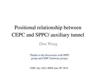
CEPC Partial Double Ring Parameter Update Dou Wang, Jiyuan Zhai, Feng Su, Yuan Zhang, Yiwei Wang, Bai Sha, Huiping Geng, Tianjian Bian,
CEPC Partial Double Ring Layout RF IP1_ee RF 3Km 1/2RF Advantage: Avoid pretzel orbit 1/2RF IP4_pp Accommodate more bunches at Z/W energy Reduce AC power with crab waist collision IP2_pp 1/2RF 1/2RF C=54710.4m RF RF IP3_ee IP1_ee/IP3_ee, 3Km IP2_pp/IP4_pp, 1132.8m 4Straights, 849.6m SU Feng 4Long ARC, 120*FODO, 5852.8m 2015.10.12 4Short ARC, 100*FODO, 4908.8m
Machine constraints / given parameters Energy E0 Circumference C0 NIP Beam power P0 y* R= y/ x Emittance coupling factor Bending radius Piwinski angle luminosity enhancement by crab waist Fl~1.5 Phase advance per cell (FODO)
Parameter choice step 1 4 0 ( ) E GeV = 3 88.5 10 U 0 ( ) m eP U = 0 I b 0 C J = q 0 Beam-beam limit: 2845 2 U E N Fl: y enhancement by crab waist = * 0 F y l 2 0 IP *J. Gao, emittance growth and beam lifetime limitations due to beam-beam effects in e+e- storage rings, Nucl. Instr. and methods A533 2004 p. 270-274.
Parameter choice step 2 ( ( ) ) ( eE GeV N N T s ( ) = + 2 1 34 [ ] 2.17 10 1 0 b e L cm s r 0 y * y ) cm 0 2845 2 U E N = 0 F y l 2 0 IP E GeV I mA P MW N 1 ( ) = 0.7 10 + 0 0 b 2 1 34 1 L cm s r 0 cm y IP
Parameter choice step 3 N 0.1 e BS life time: 30 min 2 3 r + 2 0.2 1 2 e N x z e y = 2 r N 2 x 3 3 r = y: e y z e y y + 2 1 e y x y 2 e 3 r N = ( 3) 0 = A 0 3 BS 2.6 rA A x y z e 2 y = = , r 5.77 y x y 0 y = y x 2 x + 2 1 rA y = = * x , y x x 3 4 1 60 + 2 3 2 4 1 sin sin C -- phase advance/cell, -- bending angle/cell. q 2 2 = x 3 8 sin cos J x 2 2 1 1 = 2 ( ) ( 2 ) Estimate : p 12 2 sin 2
Parameter choice step 4 + 2 2 1 I T eN = N 0 b y r = N b e x y e e y r N 2 3 0.1 = e e z 2 x 0.1 3 x = Arctg h r N 2 = tg z e e h x
Parameter choice step 5 Effective bunch length: overlap area of colliding bunches = x zeff sin h 2 y 2 y y = exp F K Hour glass effect: 0 h 2 zeff 2 zeff 2 2 zeff = L L F 0 h
Parameter choice step 6 = sin U eV 0 rf s Vrf, s 2 E A + 0 p = = R 0 0 z z 1 cos A f T eV 0 rf rf s Energy acceptance from RF: eV U 2 1 q U f T E rf = 1 arccos( ) = 2 0 q q RF 0 0 0 p rf
Parameter choice step 7 Loss factor 1.8 = ( ) / k V pC z z 0.00265 HOM power per cavity = ( ) 2 1 HOM P k eN I kw z e b
Primary parameter design Pre-CDR high lumi. low power Z Number of IPs Energy (GeV) Circumference (km) SR loss/turn (GeV) Half crossing angle (mrad) Piwinski angle Ne/bunch (1011) Bunch number Beam current (mA) SR power /beam (MW) Bending radius (km) Momentum compaction (10-5) IPx/y (m) Emittance x/y (nm) Transverse IP(um) x/IP y/IP VRF(GV) fRF(MHz) Nature z(mm) Total z(mm) HOM power/cavity (kw) Energy spread (%) Energy acceptance (%) Energy acceptance by RF (%) n Life time due to beamstrahlung_cal (minute) F (hour glass) Lmax/IP (1034cm-2s-1) 2 2 2 2 120 54 3.1 0 0 3.79 50 16.6 51.7 6.1 3.4 120 54 2.96 120 54 2.96 45.5 54 0.062 16.5 2.6 0.37 1100 36.2 2.2 6.1 5.4 0.3/0.001 1.18/0.0069 18.8/0.083 0.02 0.042 0.28 650 3.0 3.0 0.73 0.05 14.5 2 3.79 50 16.9 50 6.2 3.0 5.2 2 1.2 158 16.9 50 6.2 2.8 11.5 2 2.81 40 10.1 30 6.2 2.6 4.3 2 1.0 114 10.1 30 6.2 2.5 0.8/0.0012 6.12/0.018 69.97/0.15 0.118 0.083 6.87 650 2.14 2.65 3.6 0.13 2 6 0.23 47 0.306/0.0012 3.34/0.01 32/0.11 0.04 0.11 3.7 650 3.3 4.4 3.3 0.13 2 2.2 0.49 53 0.036/0.0012 3.07/0.0093 10.5/0.1 0.015 0.11 3.9 650 3.0 4.0 0.95 0.13 2 2.6 0.46 32 0.22/0.001 2.67/0.008 24.3/0.09 0.04 0.11 3.6 650 3.2 4.2 1.5 0.13 2 2.2 0.47 41 0.03/0.001 2.56/0.0078 8.8/0.088 0.015 0.11 3.7 650 3.0 4.0 0.47 0.13 2 2.4 0.46 32 2.0 0.08 0.68 2.04 0.73 2.97 0.75 3.07 0.69 2.03 0.7 2.08 0.67 1.01
Arc redesign-lower emittance Length of FODO cell: 47.2m Phase advance of FODO cells: 60/60 degrees Emittance: 7.9nm, p=5.38E-5 Bunch length: 2.3mm Length of FODO cell: 37.5m Phase advance of FODO cells: 60/60 degrees Emittance: 4.3nm , p=2.25E-5 Bunch length: 3.3mm
Arc redesign-ultra low emittance Length of FODO cell: 37.5m Phase advance of FODO cells: 90/60 degrees Emittance: 2.3nm, p=1.07E-5 Bunch length: 3.3mm Dispersion supressor: Angle(BDIS1)=3.583724E-03 Angle(BDIS2)=-8.598108E-04 Angle(B0)=2.723923E-03 BDIS1 BDIS2 B0 B0
summary CEPC AP group and RF group has collaborated to give a more realizable parameter considering cavity HOM power. Based on crab waist scheme, we get a set of Z parameter with 1.0*1034cm-2s-1 luminosity using 1100 bunch. Higgs s parameters have been updated to reduce the cavity HOM power under 1kw. Further improvement is undergoing to make same crossing angle as Z parameter.