Understanding Amplifiers in Electrical and Electronic Principles
In the study of Electrical, Electronic, and Digital Principles, amplifiers play a crucial role in signal processing and transmission. This lecture delves into the classification of amplifiers based on frequency capabilities, coupling methods, and usage scenarios. By exploring different classes of amplifiers such as audio, radio frequency, voltage, and power amplifiers, we gain insights into their applications, characteristics, and operational modes, such as Class B and Class AB amplifiers.
Download Presentation

Please find below an Image/Link to download the presentation.
The content on the website is provided AS IS for your information and personal use only. It may not be sold, licensed, or shared on other websites without obtaining consent from the author. Download presentation by click this link. If you encounter any issues during the download, it is possible that the publisher has removed the file from their server.
E N D
Presentation Transcript
Electrical, Electronic and Digital Principles (EEDP) Lecture 6 Amplifiers Classes .
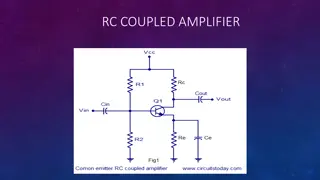
Classification Of Amplifiers 1. According to frequency capabilities. Amplifiers are classified as audio amplifiers , radio frequency amplifiers AF Amplifier are used to amplify the signals lying in the audio range ( i.e. 20 Hz to 20 kHz ) RF amplifiers are used to amplify signals having very high frequency. 2. According to coupling methods. R-C coupled amplifiers, Transformer coupled amplifiers Direct Coupled 2 EEDP - Basem ElHalawany
Classification Of Amplifiers 3. According to use. a. Voltage amplifiers Amplify the input voltage, if possible with minimal current at the output. The power gain of the voltage amplifier is low. The main application is to strengthen the signal to make it less affected by noise and attenuation. Ideal voltage amp. have infinite input impedance & zero output impedance. a. Power amplifiers Amplify the input power, if possible with minimal change in the output voltage Power amp. are used in devices which require a large power across the loads. In multi stage amplifiers, power amplification is made in the final stages Audio amplifiers and RF amplifiers use it to deliver sufficient power the load. Servo motor controllers use power it to drive the motors. 3 EEDP - Basem ElHalawany
Classification Of Amplifiers Voltage amplifiers Power amplifiers low high current gain high low Voltage gain low high Heat dissipation not required required cooling mechanism Small Large to dissipate heat Transistor Size small Wide to handle higher current Base Width Usually high >100 Low usually < 20 Beta 4 EEDP - Basem ElHalawany
Class B amplifier: When an amplifier is biased at cutoff so that it operates in the linear region for 180o of the input cycle and is in cutoff for 180o Class AB amplifiers: are biased to conduct for slightly more than 180o Both are more efficient than a class A amplifier; A disadvantage of class B or class AB is that it is more difficult to implement the circuit in order to get a linear reproduction of the input waveform. The term push-pull refers to a common type of class B or class AB amplifier circuit in which two transistors are used on alternating half-cycles to reproduce the input waveform at the output. 9 EEDP - Basem ElHalawany
The class B amplifier is biased at the cutoff point so that It is brought out of cutoff and operates in its linear region when the input signal drives the transistor into conduction. The Circuit only conducts for the positive half of the cycle. Can not amplify the entire cycle emitter-follower circuit 10 EEDP - Basem ElHalawany
To amplify the entire cycle, it is necessary to add a second class B amplifier that operates on the negative half of the cycle. The combination of two class B amplifiers working together is called push-pull operation There are two common approaches for using push-pull amplifiers to reproduce the entire waveform. 1. Transformer Coupling The input transformer thus converts the input signal to two out-of-phase signals for the two npn transistors. The output transformer combines the signals by permitting current in both directions, even though one transistor is always cut off. 11 EEDP - Basem ElHalawany
2. Complementary Symmetry Transistors The figure shows one of the most popular types of push-pull class B amplifiers using two emitter-followers and both positive and negative power supplies. This is a complementary amplifier because one emitter-follower uses an npn transistor and the other a pnp, which conduct on opposite alternations of the input cycle. 12 EEDP - Basem ElHalawany
Crossover Distortion When the dc base voltage is zero, both transistors are off and the input signal voltage must exceed VBE before a transistor conducts. Because of this, there is a time interval between the positive and negative alternations of the input when neither transistor is conducting, as shown in Figure. The resulting distortion in the output waveform is called crossover distortion. 13 EEDP - Basem ElHalawany
Biasing the Push-Pull Amplifier for Class AB Operation To overcome crossover distortion, the biasing is adjusted to just overcome the VBE of the transistors In class AB operation, the push-pull stages are biased into slight conduction, even when no input signal is present. This can be done with a voltage-divider and diode arrangement, as shown Using equal values of R1 and R2 the positive and negative supply voltages forces the voltage at point A to equal 0 V and eliminates the need for an input coupling capacitor. When the diode characteristics of D1 and D2 are closely matched to the characteristics of the transistor BE junctions, the current in the diodes and the current in the transistors are the same; ((current mirror.)) The diode current will be the same as ICQ 14
Biasing the Push-Pull Amplifier for Class AB Operation 15 AC Operation The Q-point is slightly above cutoff. (In a true class B amplifier, the Q- point is at cutoff.) The ac cutoff voltage is at VCC The ac saturation current is: In class A , the Q-point is near the middle and there is significant current in the transistors even with no signal. In class B , when there is no signal, the transistors have only a very small current and therefore dissipate very little power. Thus, the efficiency of a class B amplifier can be much higher than a class A amplifier.
The circuit operation is the same as that described previously, except the bias is set to force the output emitter voltage to be 16 EEDP - Basem ElHalawany
Maximum Output Power DC Input Power Efficiency 17
Class C amplifiers Class C amplifiers are biased so that conduction occurs for much less than 180o Class C amplifiers are more efficient than either class A , B, or AB The output amplitude is a nonlinear function of the input, so class C amplifiers are not used for linear amplification. They are generally used in radio frequency (RF) applications, including resonance circuits Basic Class C Operation A class C amplifier is normally operated with a resonant circuit load, so the resistive load is used only for the purpose of illustrating the concept. The ac source voltage has a peak value that exceeds the barrier potential of the base-emitter junction for a short time near the positive peak of each cycle, 18
Class C amplifiers Basic Class C Operation During this short interval, the transistor is turned on. The power dissipation of the transistor in a class C amplifier is low because it is on for only a small percentage of the input cycle The power dissipation during the on time is The power dissipation averaged over the entire cycle is Check EXAMPLE 7 7 (Floyde) 19
Tuned Class C Operation Because the collector voltage (output) is not a replica of the input, the resistively loaded class C amplifier alone is of no value in linear applications. It is therefore necessary to use a class C amplifier with a parallel resonant circuit (tank), as shown The short pulse of collector current on each cycle of the input initiates and sustains the oscillation of the tank circuit so that an output sinusoidal voltage is produced 20 EEDP - Basem ElHalawany


