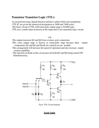
Transistor Tuned Amplifiers: Operation and Analysis
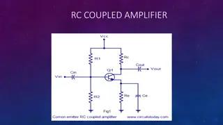
Transistor tuned amplifiers consist of a parallel tuned circuit as the collector load, amplifying a specific frequency while rejecting others. The resonant frequency of the tuned circuit is crucial for amplification. A high Q circuit offers maximum voltage gain at the resonant frequency but decreases rapidly above and below it. The AC equivalent circuit of tuned amplifiers helps in analysis and design.

Download Presentation

Please find below an Image/Link to download the presentation.
The content on the website is provided AS IS for your information and personal use only. It may not be sold, licensed, or shared on other websites without obtaining consent from the author.If you encounter any issues during the download, it is possible that the publisher has removed the file from their server.
You are allowed to download the files provided on this website for personal or commercial use, subject to the condition that they are used lawfully. All files are the property of their respective owners.
The content on the website is provided AS IS for your information and personal use only. It may not be sold, licensed, or shared on other websites without obtaining consent from the author.
E N D
Presentation Transcript
DIYALA UNIVERSITY COLLEGE OF ENGINEERING DEPARTMENT OF COMMUNICATION ENGINEERING Electronic Circuits II Second Year. Lecture 7 lecturer Wisam Hayder 2021 1
Transistor Tuned Amplifiers Single Single Tuned Tuned Amplifier Amplifier A single tuned amplifier consists of a transistor amplifier containing a parallel tuned circuit as the collector load. The values of capacitance and inductance of the tuned circuit are so selected that its resonant frequency is equal to the frequency to be amplified. The output from a single tuned amplifier can be obtained either (a) by a coupling capacitor CC as shown in Fig. 15.9 (i) or (b) by a secondary coil as shown in Fig. 15.9 (ii). 2
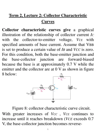
Transistor Tuned Amplifiers Operation The high frequency signal to be amplified is given to the input of the amplifier. The resonant frequency of parallel tuned circuit is made equal to the frequency of the signal by changing the value of C. Under such conditions, the tuned circuit will offer very high impedance to the signal frequency. Hence a large output appears across the tuned circuit. 4
Transistor Tuned Amplifiers In case the input signal is complex containing many frequencies, only that frequency which corresponds to the resonant frequency of the tuned circuit will be amplified. All other frequencies will be rejected by the tuned circuit. In this way, a tuned amplifier selects and amplifies the desired frequency. 5
Transistor Tuned Amplifiers Analysis of TunedAmplifier Fig. 15.10 (i) shows a single tuned amplifier. Note the presence of the parallel LC circuit in the collector circuit of the transistor. When the circuit has a high Q, the parallel resonance occurs at a frequency fr given by: 6
Transistor Tuned Amplifiers The voltage gain is maximum at fr. However, above and below the resonant frequency, the voltage gain decreases rapidly. The higher the Q of the circuit, the faster the gain drops off on either side of resonance [See Fig. 15.10 (ii)]. 7
Transistor Tuned Amplifiers A.C. Equivalent Circuit of Tuned Amplifier A.C. Equivalent Circuit of Tuned Amplifier Fig. 15.11 (i) shows the ac equivalent circuit of the tuned amplifier. Note the tank circuit components are not shorted. In order to completely understand the operation of this circuit, we shall see its behaviour at three frequency conditions viz., (i) When input frequency equals fr (i.e., fin = fr). When the frequency of the input signal is equal to fr, the parallel LC circuit offers a very high impedance i.e., it acts as an open. Therefore, voltage across RL is maximum i.e., the voltage gain is maximum as shown in Fig. 15.11 (ii). 8
Transistor Tuned Amplifiers (ii) When input frequency is less than fr (i.e., fin < fr ). When the input signal frequency is less than fr, the circuit is effectively* inductive. As the frequency decreases from fr, a point is reached when ??_ ??=??. When this happens, the voltage gain of the amplifier falls by 3 db. In other words, the lower cut-off frequency f1 for the circuit occurs when ??_ ??=??. 9
Transistor Tuned Amplifiers (iii) When input frequency is greater than fr (i.e., fin > fr). When the input signal frequency is greater than fr, the circuit is effectively capacitive. As fin is increased beyond fr, a point is reached when ??_ ??=??. When this happens, the voltage gain of the amplifier will again fall by 3db. In other words, the upper cut-off frequency for the circuit will occur when ??_ ??=??. However, the impedance of the circuit decreases rapidly when the frequency is changed above or below the resonant frequency. 10
Transistor Tuned Amplifiers Example 15.7. For the tuned amplifier shown in Fig. 15.12, determine (i) the resonant frequency (ii) the Q of tank circuit and (iii) bandwidth of the amplifier. 11
Transistor Tuned Amplifiers Double Tuned Amplifier Double Tuned Amplifier Fig. 15.13 shows the circuit of a double tuned amplifier. It consists of a transistor amplifier containing two tuned circuits ; one (?1?1) in the collector and the other (?2?2) in the output as shown. The high frequency signal to be amplified is applied to the input terminals of the amplifier. The resonant frequency of tuned circuit ?1?1is made equal to the signal frequency. Under such conditions, the tuned circuit offers very high impedance to the signal frequency. 13
Transistor Tuned Amplifiers Consequently, large output appears across the tuned circuit ?1?1. The output from this tuned circuit is transferred to the second tuned circuit ?2?2through mutual induction. Double tuned circuits are extensively used for coupling the various circuits of radio and television receivers. 14
Transistor Tuned Amplifiers Frequency response The frequency response of a double tuned circuit depends upon the degree of coupling i.e. upon the amount of mutual inductance between the two tuned circuits. When coil ?2is coupled to coil ?1[See Fig. 15.14 (i)], a portion of load resistance is coupled into the primary tank circuit ?1?1and affects the primary circuit in exactly the same manner as though a resistor had been added in series with the primary coil ?1. 15
Transistor Tuned Amplifiers When the coils are spaced apart, all the primary coil L1 flux will not link the secondary coil L2. The coils are said to have loose coupling. Under such conditions, the resistance reflected from the load (i.e. secondary circuit) is small. The resonance curve will be sharp and the circuit Q is high as shown in Fig. 15.14 (ii). When the primary and secondary coils are very close together, they are said to have tight coupling. Under such conditions, the reflected resistance will be large and the circuit Q is lower. Two positions of gain maxima, one above and the other below the resonant frequency, are obtained. 17
Transistor Tuned Amplifiers Bandwidth of Double Bandwidth of Double Tuned Circuit Tuned Circuit For a given frequency, the tighter the coupling, the greater is the bandwidth. ????= ??? The subscript dt is used to indicate double-tuned circuit. Here k is coefficient of coupling. 18
Transistor Tuned Amplifiers Practical Application of Double Tuned Amplifier Practical Application of Double Tuned Amplifier Double tuned amplifiers are used for amplifying radio- frequency (RF) signals. One such application is in the radio receiver as shown in Fig. 15.15. This is the IF stage using double tuned resonant circuits. Each resonant circuit is tuned to 455 kHz. The critical coupling occurs when the coefficient of coupling is 19
Transistor Tuned Amplifiers When two resonant circuits are critically coupled, the frequency response becomes flat over a considerable range of frequencies as shown in Fig. 15.16. In other words, the double tuned circuit has better frequency response as compared to that of a single tuned circuit. The use of double tuned circuit offers the following advantages: (i) Bandwidth is increased. (ii) Sensitivity (i.e. ability to receive weak signals) is increased. (iii) Selectivity (i.e. ability to discriminate against signals in adjacent bands) is increased. 21
Operational Amplifiers (Op-Amp) Introduction Amplifiers are used extensively in electronic circuits to make an electronic signal bigger without affecting it in any other way. An amplifier, electronic amplifier or (informally) amp is an electronic device that increases the power of a signal. Amplifiers are two-port networks in which the output voltage or current is directly proportional to either input voltage or current. 25
Operational Amplifiers (Op-Amp) Operational Amplifier or Op-Amp is a multistage amplifier that is used for general electrical signal manipulation general electrical signal manipulation. An amplifier is used to increase the amplitude of a signal waveform, without changing other parameters of the waveform such as frequency or wave shape. They are one of the most commonly used circuits in electronics and perform a variety of functions in a great many electronic systems. The general symbol for an amplifier is shown in Fig. below. The symbol gives no detail of the type of amplifier described, but the direction of signal flow can be assumed (as flowing from left to right of the diagram). Amplifiers of different types are also often described in system or block diagrams by name. 26


")
")
")
")
")
")