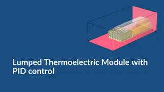
Temperature Rise Simulation of Electric Power Connector
This project involves the simulation of temperature rise in electric power connectors used for high ampacity HTLS conductors, aiming to ensure the maximum temperature remains below 85°C as per standard IS 5561. The study includes the design requirements, material properties, FEA analysis, and simulation results with and without a heatsink in the conduction path.

Download Presentation

Please find below an Image/Link to download the presentation.
The content on the website is provided AS IS for your information and personal use only. It may not be sold, licensed, or shared on other websites without obtaining consent from the author. Download presentation by click this link. If you encounter any issues during the download, it is possible that the publisher has removed the file from their server.
E N D
Presentation Transcript
Temperature Rise Simulation Of Electric Power Connector Prepared by: Abhijnan Chowdhuri Raghav Upasani Ishant Jain 22
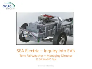
Background For 220/400 KV line, ACSR Zebra ( 28.62 mm) and ACSR Moose ( 31.77 mm) conductors are been used having current carrying capacity of 1000 Amps each Increase in demand for Electrical Power Generation & Transmission, there exist a few hindrances High cost to install new Power lines Difficulty in acquiring Tower sites Right of way (ROW) Large time involved in constructing new Power lines Fig 1. 3 keeper connector for ACSR Zebra & ACSR Moose Therefore, High Temperature Low Sag (HTLS) conductors, having high ampacity, which can deliver large power without any change in existing tower design are been used. Hence there is need to design connector for HTLS conductor having permissible temperature as per IS 5561 Fig 2. Twin Connector for HTLS 3 3
Problem Definition Design of the connector should be such that the maximum allowed temperature should be less than 85 C including the ambient temperature at 1600 A as per standard IS 5561. Moreover, the connectors that are being used for HTLS cables should be made up of IS 5561 (AL - 4600 & A6 grade) or equivalent grade of aluminium as per standard IS 617. Need for FEA Helps to study response of the system based on loading condition in real world situation To determine the correctness and efficiency of a design before the system is actually constructed Reduces lead time and cost to product 4 4
Temperature Rise Simulation as per IS 5561 A. Geometry C. Physics & Multiphysics Used G Joule Heating G: Ground T: Terminal (1600 Amp) G T B. Material Properties Connector (Al) Properties HTLS Conductor (Al-Zr) Properties Property Value Unit Property Value Unit 3.5x10⁷ Electrical Conductivity S/m 1.38x10⁷ Electrical Conductivity S/m Relative Permittivity 1 1 Relative Permittivity 1 1 Thermal Conductivity 219 W/m-K Thermal Conductivity 169 W/m-K Density 2705 Kg/m Density 2517 Kg/m Heat Capacity at constant Pressure Heat Capacity at constant Pressure 960 J/Kg-K 943 J/Kg-K 5 5
Temperature Rise Simulation as per IS 5561 D.1 Result - T-CONNECTORWITHNOHEATSINKINCONDUCTIONPATH G G: Ground G T: Terminal (1500 Amp) Maxm Temp. Reached in Connector 95.60C i.e ambient 400C + rise 55.60C T 6 6
Temperature Rise Simulation as per IS 5561 D.2 Result - T-CONNECTORWITHONEHEATSINKINCONDUCTIONPATH G G: Ground G T: Terminal (1500 Amp) Maxm Temp. Reached in Connector 70.50C i.e ambient 400C + rise 30.50C T 7 7
Temperature Rise Simulation as per IS 5561 D.3 Result - T-CONNECTORWITHTWOHEATSINKINCONDUCTIONPATH G G: Ground T: Terminal (1500 Amp) G 8 8
Conclusion Multiple iterations were carried out in designing of T- Connector based on simulation results in order to increase optimum surface area of connector. Current requirement was high, hence heat sink were incorporated along with the connector to reduce the temperature rise as shown below. T-Connector With Temperature Max Temperature Rise ( C) ( C) No heat sink 95.6 55.6 One heat sink 70.5 30.5 Two heat sink 60.1 20.1 Fast heat dissipation and high mechanical strength of the heat sink played a decisive factor in reducing the maximum temperature of the T-connector. Future Work Prototyping, Real life testing & Validation needs to be done. 9 9
THANK YOU 10
Questions? 11