Innovative Solution for Long Mating Connector Alignment
This solution addresses alignment concerns over a 3m distance between connector boards by modifying the PCB design, using oversized holes, and implementing a new assembly sequence. By replacing connectors, strategically assembling components, and soldering carefully, the process ensures successful mating with enhanced accuracy and efficiency.
Download Presentation

Please find below an Image/Link to download the presentation.
The content on the website is provided AS IS for your information and personal use only. It may not be sold, licensed, or shared on other websites without obtaining consent from the author.If you encounter any issues during the download, it is possible that the publisher has removed the file from their server.
You are allowed to download the files provided on this website for personal or commercial use, subject to the condition that they are used lawfully. All files are the property of their respective owners.
The content on the website is provided AS IS for your information and personal use only. It may not be sold, licensed, or shared on other websites without obtaining consent from the author.
E N D
Presentation Transcript
A Solution to the 3m Long Mating Connector Problem
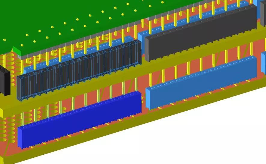
Current PCB design Use Samtec SSQ connectors on anode 2 to connect both the sockets on anode 1, and the pins on adapter boards. There are concerns over the alignment of the pins over the 3m length of the boards between anode 1 and 2. Maximum length of the adapter board is <0.9m. Apparently, people at CERN have stacked boards 2m in length.
Changes to the current PCB design On Anode 2: Remove the SSQ connectors on the Anode 2 Drill oversized holes (~2mm) where the SSQ pins passed through
Changes to the current PCB design On the adapter boards: Replace the outer row of pins from TSW to longer MTSW connectors
New Assembly Sequence, 1 Instead of plugging Anode 2 into Anode 1, then Adapter to Anode 2+1, we need to assemble Anode 2 + adapter boards first. Place the MTSW pins through the large holes on anode 2 Anode 2 needs to be elevated off the table top for the long pins
New Assembly Sequence, 2 Position the Anode 2 + adapter board assembly over Anode 1. Lower the assembly toward the Anode 1 until the MTSW connectors have been pushed up nearly reaching the adapter boards. Plug in each of the MTSW connectors into the mating SSM sockets
New Assembly Sequence, 3 Continue lower the Anode 1+ Adapter assembly until about 2mm above nominal gap. Place spacers between Anode 1 and 2 to maintain the gap. Pull each MTSW connector up into the PTHs on the adapter board, while keeping the bottom of the pins constrained in the SSM sockets on Anode 1. Solder the MTSW connector to the adapter board
New Assembly Sequence, 4 Fully lower the Anode 2 + adapter to the nominal height over Anode 1. Carefully clean the new solder joints on the adapter board.
A Variant Instead of using oversized holes for the long pins to pass through, simply cut off the edge of the board. This saves the trouble of embedding the long pins into the Anode2+adapter assembly. The long pins can be inserted into the SSM sockets on the anode 1 directly. The through holes provide some protection to the pins during handling from accidental bumps.
Summary This concept solves the problem of maintaining perfect alignment of pins over a 3m length for the initial pin insertion. It assumes that the conventional pins and sockets interconnect over a 0.9m distance (adapter length) can be done without too much difficulty. Other steps to improve alignment: Larger PTHs on the adapter boards for the pins Use a common alignment fixture to bond the anode PCBs to ensure alignment uniformity This approach still leaves the question open if the two anode boards need to be separated and re-engaged. Although the problem might be partially solved by the in-position soldering of the connectors, therefore more or less maintaining the alignment.
Another solution with no soldering on the large PCBs Build a row of side mounted PCB with multiple edge card connectors. These side PCBs plug onto the edges of all 3 layers of large PCBs. All soldering done on the small side PCBs, which can be mass produced. Downside: larger dead space between CRPs.
Other alternatives Similar construction, but with additional shroud or guide to maintain alignment of the pins on the same connector. We can also make special alignment tools to nudge the pins before engaging to the sockets. Samtec ZSS Samtec ZW
Non-Pin and socket alternatives Use edge card sockets with strips of PCB to bridge the anode. Use FPC connectors (ZIF) and flexible printed circuit jumpers. Common drawback: high density connectors for very low density (~10mm) connection: a lot of manual soldering due to the size of the boards. Edge card sockets Samtec MEC2 (5.6mm wide) Flexible Printed Circuit (3-4mm wide)


