Understanding Rectification Technologies in Electrical Engineering
Exploring the world of rectification in electrical engineering, this lecture covers the motivation behind using AC to DC conversion, various rectification technologies including electromechanical and diode-based solutions, types of rectification such as half wave and full wave, and practical applications of rectifier circuits. Dive into the fundamentals of converting AC voltage to DC voltage and gain insights into the historical perspective and modern advancements in this essential electrical engineering concept.
- Rectification Technologies
- Electrical Engineering
- AC to DC Conversion
- Diode Rectifiers
- Rectification Circuits

Download Presentation

Please find below an Image/Link to download the presentation.
The content on the website is provided AS IS for your information and personal use only. It may not be sold, licensed, or shared on other websites without obtaining consent from the author. Download presentation by click this link. If you encounter any issues during the download, it is possible that the publisher has removed the file from their server.
E N D
Presentation Transcript
CONVERTERS By Ch. Sai Ram, Associate Professor, Sri Indu College of Engineering & Technology, SICET 1
Outline Motivation Rectification Technologies Types of Rectification Rectification Circuits Applications Objective of this Lecture To teach you how to use different types of rectifier circuits to convert AC voltage to DC voltage SICET 2
Motivation Early experiments with Direct Current (DC) power relied on Leyden jars (rudimentary batteries) which had to be recharged via manual labor (e.g. grad students) Due to efficiency and safety reasons, Alternating Current (AC) is used for providing electrical power A means to convert AC to DC is required - called Rectification SICET 3
Rectification Technologies Electromechanical Synchronous rectifier Used motor attached to metal contacts that switched direction of current flow in time with AC input voltage Motor-generator set An AC motor coupled to DC generator Electrolytic Two different material electrodes suspended in electrolyte provide different resistance depending on current flow Vacuum Tube Capable of high voltages, but relatively low current Mercury arc rectifier A sealed vessel with mercury in it provides DC power by transmitting electricity through ionized mercury vapor Capable of power on order of hundreds of kilowatts SICET 4
Rectification Technologies Rectification Based on Diode Rectification is most popular application of diode Diodes provide compact and inexpensive means of rectification Can create rectifiers from multiple diodes or purchase integrated module Diodes Diode Rectifier Modules SICET 5
Types of Rectification Half Wave Rectifier Full Wave Rectifier While output of the rectifiers is now DC (current only flows in one direction), output oscillates SICET 6
Types of Rectification Half Wave: Negative components of sine wave are discarded Full Wave: Negative components are inverted SICET 7
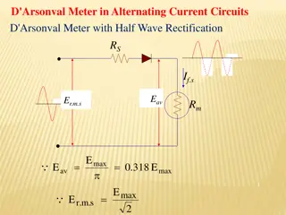
Rectification Circuit: Half-Wave Simplest kind of rectifier circuit is half-wave rectifier. Allows one half of AC waveform to pass through to load. Converts alternating current (AC) to direct current (DC). Involves device that only allows one-way flow of electrons, and this is exactly what semiconductor diode does. Half-wave rectifier circuit SICET 8
Rectification Circuit: Half-Wave For most power applications, half-wave rectification is insufficient for task. Harmonic content of rectifier's output waveform is very large and consequently difficult to filter. AC power source only supplies power to load once every half-cycle, meaning that much of its capacity is unused. Half-wave rectification is, however, very simple way to reduce power to resistive load. Two-position lamp dimmer switches apply full AC power to lamp filament for full brightness and then half-wave rectify it for a lesser light output. Half-wave rectifier application: Two level lamp dimmer. SICET 9
Rectification Circuit: Half-Wave In Dim switch position, incandescent lamp receives approximately one-half power it would normally receive operating on full-wave AC. Because half-wave rectified power pulses far more rapidly than filament has time to heat up and cool down, lamp does not blink. Instead, its filament merely operates at lesser temperature than normal, providing less light output. This principle of pulsing power rapidly to slow-responding load device to control electrical power sent to it is common in world of industrial electronics. Since controlling device (diode, in this case) is either fully conducting or fully non- conducting at any given time, it dissipates little heat energy while controlling load power, making this method of power control very energy-efficient. This circuit is perhaps crudest possible method of pulsing power to a load, but it suffices as a proof-of-concept application SICET 10
Rectifier Circuit: Full-Wave If we need to rectify AC power: In order obtain full use of both half-cycles of sine wave Full-wave rectifier must be used Types of full-wave rectifier: Center-tap design Full-wave bridge. Polyphase: Three-phase full-wave bridge rectifier circuit. Center-tap design Uses transformer with center-tapped secondary winding and two diodes Full-wave rectifier, center-tapped design SICET 11
Rectifier circuit Look at its circuit operation one half-cycle at a time. Consider first half-cycle: Source voltage polarity is positive (+) on top and negative (-) on bottom. Only top diode is conducting; bottom diode is blocking current, and load sees first half of sine wave. Only top half of transformer's secondary winding carries current during this half- cycle. Full-wave center-tap rectifier: Top half of secondary winding conducts during positive half-cycle of input, delivering positive half-cycle to load SICET 12
Rectifier circuit Consider next (second) half-cycle: AC polarity reverses Other diode and other half of transformer's secondary winding now carry current Portions of circuit formerly carrying current during first half-cycle sit idle Load still sees half of sine wave, of same polarity as before. Full-wave center-tap rectifier: During negative input half-cycle, bottom half of secondary winding conducts, delivering a positive half-cycle to the load. SICET 13
Rectifier circuit Dual Polarity Full-Wave By changing direction of diodes: Full-wave center-tapped rectifier polarity at load may be reversed. Furthermore, reversed diodes can be paralleled with existing positive-output rectifier. Result is dual-polarity full-wave center-tapped rectifier. Note: connectivity of diodes themselves is same configuration as bridge. Dual polarity full-wave center tap rectifier SICET 14
Rectifier Circuit: Full-Wave One disadvantage of this full-wave rectifier design is: Necessity of transformer with center-tapped secondary winding. If circuit in question is one of high power: Size and expense of suitable transformer will be significant. Consequently: Center-tap rectifier design is only seen in low-power applications SICET 15
Rectifier Circuit Full-wave Bridge Rectifier. More popular full-wave rectifier design Built around four-diode bridge configuration. For obvious reasons, this design is called full-wave bridge. Full-wave bridge rectifier SICET 16
Rectifier Circuit Full-wave Bridge Current directions for positive and negative half-cycles of: AC source waveform are shown below and next page respectively. Note: regardless of polarity of input, current flows in same direction through load. That is, negative half-cycle of source is positive half-cycle at load. Full-wave bridge rectifier: Electron flow for positive half-cycles SICET 17
Rectifier circuit: Full-Wave Bridge Full-wave bridge rectifier: Electron flow for negative half -cycles. Current flow is through two diodes in series for both polarities. Thus, sum of voltage drops for two diodes is 2(0.7) volts This is disadvantage when compared to full-wave center-tap design. Will only be problem in very low voltage power supplies SICET 18
Output Ripple Output ripple will always be present in circuits shown above Amplitude of ripple can be reduced by adding smoothing capacitor Capacitor and load (shown here as resistor) from low pass filter with time constant : T = RC Time constant should be much longer than one ripple For given ripple amplitude: capacitor size (in microfarads) is given by f: line frequency Iload: Load Current Vrip: Amplitude of ripple voltage NOTE: Voltage rating of the capacitor must be > 1.4*Vout Large capacitors should have bleeder resistors for safety! SICET 19
Rectifier circuit Sometimes, method of rectification is referred to by counting number of DC pulses output for every 360oof electrical rotation. Single-phase, half-wave rectifier circuit, then, would be called 1-pulse rectifier, because it produces single pulse during time of one complete cycle (360o) of AC waveform. Single-phase, full-wave rectifier (regardless of design, center-tap or bridge) would be called 2-pulse rectifier, because it outputs two pulses of DC during one AC cycle's worth of time. SICET 20
Rectifier Circuit: Output Voltage Full wave rectification will produce voltage roughly equal to V0= 2Vrms In practice, there will be small voltage drop across diodes that will reduce this voltage For accurate supplies, regulation is necessary SICET 21
Rectifier circuit REVIEW: Rectification is conversion of alternating current (AC) to direct current (DC). A half-wave rectifier is circuit that allows only one half-cycle of AC voltage waveform to be applied to load, resulting in one non-alternating polarity across it. A full-wave rectifier is circuit that converts both half-cycles of AC voltage waveform to unbroken series of voltage pulses of same polarity. SICET 22
Rectification: Applications DC Power supplies Used to provide DC power to drive loads Radios Used to rectify received radio signals as part of AM demodulation Signal to be transmitted is multiplied by a carrier wave Diode in receiver rectifies signal Rectified Radio Wave Modulated Signal Radio Transmission Audio Signal SICET 23
Applications Light Dimmer Sends unrectified or half wave AC power through light bulb Automobile Alternators Output of 3-phase AC generator is rectified by diode bridge More reliable than DC generator 6 Rectifier Diodes SICET 24
References http://en.wikipedia.org/wiki/Rectifier http://en.wikipedia.org/wiki/Diode_bridge http://www.allaboutcircuits.com/vol_3/chpt_3/4.html http://my.integritynet.com.au/purdic/power1.html http://electronics.howstuffworks.com/radio.htm SICET 25