Understanding FSMD: FSM with Datapath in FPGA Design
Explore the concept of Finite State Machine with Datapath (FSMD) in FPGA design, as discussed in the lecture at George Mason University. Learn about translating sequential algorithms into hardware, using registers and control paths to simulate variables, and realizing systems through RTL design. Discover the fundamentals of single register transfer operations and FSMD conceptual block diagrams for efficient hardware implementation.

Download Presentation

Please find below an Image/Link to download the presentation.
The content on the website is provided AS IS for your information and personal use only. It may not be sold, licensed, or shared on other websites without obtaining consent from the author. Download presentation by click this link. If you encounter any issues during the download, it is possible that the publisher has removed the file from their server.
E N D
Presentation Transcript
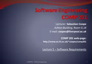
ECE 448 Lecture 7 FSMD: FSM with a Datapath George Mason University
Required reading P. Chu, FPGA Prototyping by VHDL Examples Chapter 6, FSMD 2
Introduction fsmd FPGA Prototyping by VHDL Examples (2nd ed.) 3
Algorithm to hardware Two characteristics of a sequential algorithm: Use of variables (as symbolic memory locations) e.g., n = n + 1 in C Sequential execution: implicitly specifies the order of operation Realize algorithm in hardware Use registers to store intermediate data (to imitate variables) Use a datapath to realize all register operations Use a control path (FSM) to specify the order of register operation fsmd FPGA Prototyping by VHDL Examples (2nd ed.) 4
Algorithm to hardware (cont.) Resulting system Specified as sequence of data manipulation/transfer among registers Realized by an FSMD (FSM with a datapath) The scheme sometimes referred to as RTL (register-transfer level) design fsmd FPGA Prototyping by VHDL Examples (2nd ed.) 5
Algorithm to hardware (cont.) FSMD Conceptual block diagram fsmd FPGA Prototyping by VHDL Examples (2nd ed.) 6
Single RT (register transfer) operation Basic form: Interpretation: At the rising edge of the clock, the output of registers rsrc1 rsrc2 . etc are available The output are passed to a combinational circuit that performs f( ) At the next rising edge of the clock, the result is stored into rdest fsmd FPGA Prototyping by VHDL Examples (2nd ed.) 7
Single RT operation (cont.) E.g., r1 0 : 0 stored in r1 register r1 r1: content of r1 written back to itself r2 r1: content of r1 transferred to r2 r2 r2 >> 3: r2 shifted right 3 bits and written back i i + 1: i incremented and written d s1 + s2 + s3: sum of s1, s2 and s3 written to d y a*a: a squared written to y fsmd FPGA Prototyping by VHDL Examples (2nd ed.) 8
Single RT operation (cont.) Implementation/timing example:a a b +1 fsmd FPGA Prototyping by VHDL Examples (2nd ed.) 9
ASMD chart FSM is good to control RT operation State transition is on clock-by-clock basis FSM can enforce order of execution FSM allows branches on execution sequence RT operation can be added to an ASM chart Referred to as ASMD (ASM with a datapath) chart fsmd FPGA Prototyping by VHDL Examples (2nd ed.) 10
ASMD chart (cont.) E.g., ASMD segment with one data register (r1) fsmd FPGA Prototyping by VHDL Examples (2nd ed.) 11
ASMD chart (cont.) E.g., ASMD block with both Moore and Mealy control (via conditional boxes) fsmd FPGA Prototyping by VHDL Examples (2nd ed.) 12
Decision box with a register In an ASMD chart, the register is updated when the FSM exits current state Detailed timing diagram: r1 is only available when the FSM exits s1 state fsmd FPGA Prototyping by VHDL Examples (2nd ed.) 13
Decision box with a register (cont.) When a registered output (e.g., r) used in a decision box, it may appear to be delayed by one clock Fix: define a next-state value (e.g., r_next) and use it instead E.g., fsmd FPGA Prototyping by VHDL Examples (2nd ed.) 14
Code Development fsmd FPGA Prototyping by VHDL Examples (2nd ed.) 15
Basic coding style Explicit-data-path style Separate FSM and control data path FSM: state register/ next-state logic / output logic Data path: data register / functional units Implicit-data-path style Follow the FSM two-segment coding style Incorporate the RT operations in FSM states/transitions Mixed style Similar to Implicit-data-path style But extract complex data-path functional units (such as multiplier and barrel shifter) for sharing fsmd FPGA Prototyping by VHDL Examples (2nd ed.) 16
Debouncing circuit revisited When moved, contact of a mechanical switches may bounce a few times Bounces settle down in 20 ms Debounceing circuit generates a clean transition Two schemes: Delayed detection: respond until the signal is stable for at least 20 ms Early detection: respond immediately but ignore transitions in the next 20 ms fsmd FPGA Prototyping by VHDL Examples (2nd ed.) 17
Debouncing circuit (cont.) fsmd FPGA Prototyping by VHDL Examples (2nd ed.) 18
FSMD based debouncing circuit FSM based design Uses an independent free- running 10-ms timer Not accurate: checking settling time between 20 and 30ms Better FSMD based: Embed counting in data path With 100 MHz clock, # clocks = 20 ms /10 ns fsmd FPGA Prototyping by VHDL Examples (2nd ed.) 19
FSMD based debouncing circuit Input: sw: switch Output: db_level: debounced sw db_tick: 1-clock pulse for a valid 0-to-1 transition fsmd FPGA Prototyping by VHDL Examples (2nd ed.) 20
FSMD based debouncing circuit (cont.) Data path: q register + decrementer Function as a counter FSM: zero / one states sw signal is settled at 0/1 load q with 1 1 when a transition is detected wait0 / wait1 states: sw signal is in transition Decrementing q provides the needed settling time signal is settled when q reaches 0 fsmd FPGA Prototyping by VHDL Examples (2nd ed.) 21
Explicit-data-path style Separate segments for data path and FSM Data path Q register + decrementer Q can be reloaded or decremented Code library ieee; use ieee.std_logic_1164.all; use ieee.numeric_std.all; entity debounce is port( clk, reset : in std_logic; sw : in std_logic; db_level : out std_logic; db_tick : out std_logic ); end debounce; fsmd FPGA Prototyping by VHDL Examples (2nd ed.) 22
architecture exp_fsmd_arch of debounce is constant N: integer:=21; -- 2^N * 10ns = 20ms type state_type is (zero, wait0, one, wait1); signal state_reg, state_next : state_type; signal q_reg, q_next :unsigned(N - 1 downto 0); signal q_load, q_dec, q_zero : std_logic; begin -- FSMD state & data registers process(clk,reset) begin if reset='1' then state_reg <= zero; q_reg <= (others=>'0'); elsif (clk'event and clk='1') then state_reg <= state_next; q_reg <= q_next; end if; end process; fsmd FPGA Prototyping by VHDL Examples (2nd ed.) 23
-- FSMD data path (counter) next-state logic q_next <= (others=>'1') when q_load='1' else q_reg - 1 when q_dec='1' else q_reg; q_zero <= '1' when q_next=0 else '0'; fsmd FPGA Prototyping by VHDL Examples (2nd ed.) 24
-- FSMD control path next-state logic process(state_reg,sw,q_zero) begin q_load <= '0'; q_dec <= '0'; db_tick <= '0'; state_next <= state_reg; case state_reg is when zero => db_level <= '0'; if (sw='1') then state_next <= wait1; q_load <= '1'; end if; when wait1=> db_level <= '0'; if (sw='1') then q_dec <= '1'; if (q_zero='1') then state_next <= one; db_tick <= '1'; end if; else -- sw='0' state_next <= zero; end if; fsmd FPGA Prototyping by VHDL Examples (2nd ed.) 25
when one => db_level <= '1'; if (sw='0') then state_next <= wait0; q_load <= '1'; end if; when wait0=> db_level <= '1'; if (sw='0') then q_dec <= '1'; if (q_zero='1') then state_next <= zero; end if; else -- sw='1' state_next <= one; end if; end case; end process; end exp_fsmd_arch; fsmd FPGA Prototyping by VHDL Examples (2nd ed.) 26
Implicit-data-path style RT operations are incorporated in FSM state/transitions Data path functional units are embedded implicitly Code Same entity declaration, signal declaration, state/data register as before New combinational circuit code segment for the FSM next-state logic and RT computation fsmd FPGA Prototyping by VHDL Examples (2nd ed.) 27
-- next-state logic & data path functional units process(state_reg,q_reg,sw,q_next) begin state_next <= state_reg; q_next <= q_reg; db_tick <= '0'; case state_reg is when zero => db_level <= '0'; if (sw='1') then state_next <= wait1; q_next <= (others=>'1'); end if; when wait1=> db_level <= '0'; if (sw='1') then q_next <= q_reg - 1; if (q_next=0) then state_next <= one; db_tick <= '1'; end if; else -- sw='0' state_next <= zero; end if; fsmd FPGA Prototyping by VHDL Examples (2nd ed.) 28
when one => db_level <= '1'; if (sw='0') then state_next <= wait0; q_next <= (others=>'1'); end if; when wait0=> db_level <= '1'; if (sw='0') then q_next <= q_reg - 1; if (q_next=0) then state_next <= zero; end if; else -- sw='1' state_next <= one; end if; end case; end process; fsmd FPGA Prototyping by VHDL Examples (2nd ed.) 29
Comparison of two styles Implicit-data-path style Just follow the ASMD chart Clear, descriptive, and easy to code Rely on synthesis software to create data path Explicit-data-path style Can manually craft data path to obtain optimized circuit FSM and data path interacts via command and status signals Tedious to code fsmd FPGA Prototyping by VHDL Examples (2nd ed.) 30
Mixed Style Similar to Implicit-data-path style, but identify and extract complex data-path functional units E.g., binary multiplier (*) is a very complex and should be shared case when s1 d1_next <= a * b; . . . when s2 d2_next <= b * c; . . . when s3 d3_next <= a * c; . . . end case; fsmd FPGA Prototyping by VHDL Examples (2nd ed.) 31
Mixed Style (cont.) Extract * for sharing case when s1 in1 <= a; in2 <= b; d1_next <= m_out; . . . when s2 in1 <= b; in2 <= c; d2_next <= m_out; . . . when s3 in1 <= a; in2 <= c; d3_next <= m_out; . . . end case; -- explicit description of a single multiplier m_out <= in1 * in2; fsmd FPGA Prototyping by VHDL Examples (2nd ed.) 32
Algorithm-to-Hardware Example: Shift-and-Add Multiplier fsmd FPGA Prototyping by VHDL Examples (2nd ed.) 33
Hardware acceleration FSMD can be used to implement software algorithm Custom hardware can accelerate operation Hardware can explore parallelism Hardware can implement less-used operation Hardware can reduce processor overhead (instruction fetch, decoding etc.) Hardware accelerator frequently used to complement processor to speed up computation intensive tasks (e.g., encryption, machine vision) fsmd FPGA Prototyping by VHDL Examples (2nd ed.) 34
Shift-and-add multiplication algorithm Hardware multiplier sometimes is not available Multiplication can be done by additions E.g., multiplication of 4-bit unsigned binary numbers fsmd FPGA Prototyping by VHDL Examples (2nd ed.) 35
Shift-and-add algorithm (cont.) Basic Idea (shown with 4-bit inputs) Process multiplier (i.e., b3b2b1b0) one bit at a time If bit n (i.e., bn) is 1, Shift multiplicand (i.e., a3a2a1a0) to left n positions Add the shifted value to product Repeat the procedure sequentially 4 times fsmd FPGA Prototyping by VHDL Examples (2nd ed.) 36
Shift-and-add algorithm (cont.) function (with 8-bit unsigned operands) in C uint16_t mult(uint8_t a_in, uint8_t b_in) { uint16_t a, p; uint8_t b, n; a = (uint16_t)a_in; b = b_in; n = 8; p = 0; while (n != 0) { n = n - 1; if((b>>n & 0x01)==1) { p = p + (a << n); } } return (p); } fsmd FPGA Prototyping by VHDL Examples (2nd ed.) 37
Shift-and-add algorithm (cont.) Modifications are needed to facilitate hardware implementation. Replacement of while loop ASMD chart does not support high-level control constructs (while and for loops in C) directly These constructs should be replaced by primitive if/goto statements (which resemble decision box/exit paths) Avoidance of complex operators Complexity of hardware operators varies General-purpose shift function ( << n , where n is not static) infers complex barrel shifter Shifting constant position (e.g., <<1 ) involves reconnection of input/output wire and is very simple fsmd FPGA Prototyping by VHDL Examples (2nd ed.) 38
Shift-and-add algorithm (cont.) Hardware friendly C function uint16_t mult(uint8_t a_in, uint8_t b_in) { uint16_t a, b, n, p; a = a_in; b = b_in; n = 8; p = 0; OP: if ((b & 0x01) == 1) { p = p + a; } a = a << 1; b = b >> 1; n = n - 1; if (n != 0) { goto OP;} return (p); } fsmd FPGA Prototyping by VHDL Examples (2nd ed.) 39
Shift-and-add algorithm (cont.) Convert C code segment to ASMD chart Map variable assignment statement(s) to an ASMD state Multiple unrelated statements can be grouped and mapped to a single ASMD state Operations are done in parallel in the same clock cycle Embed if/got statements as decision boxes in ASM blocks One if statement may be embedded into multiple blocks Add necessary command and status signals E.g., a start signal to initiate the operation E.g., a ready signal to indicate whether the computation is done fsmd FPGA Prototyping by VHDL Examples (2nd ed.) 40
Shift-and-add algorithm (cont.) ASMD chart In a default RT operation, register keeps its previous value Default RT operation not shown in chart fsmd 41 FPGA Prototyping by VHDL Examples (2nd ed.)
Shift-and-add algorithm (cont.) HDL code library ieee; use ieee.std_logic_1164.all; use ieee.numeric_std.all; entity seq_mult is port( clk, reset: in std_logic; start: in std_logic; a_in, b_in: in std_logic_vector(7 downto 0); ready: out std_logic; r: out std_logic_vector(15 downto 0) ); end seq_mult; FPGA Prototyping by VHDL Examples (2nd ed.) fsmd 42
architecture shift_add_arch of seq_mult is constant WIDTH: integer:=8; constant C_WIDTH: integer:=4; -- width of the counter constant C_INIT: unsigned(C_WIDTH-1 downto 0):="1000"; type state_type is (idle, add, shift); signal state_reg, state_next: state_type; signal b_reg, b_next: unsigned(WIDTH-1 downto 0); signal a_reg, a_next: unsigned(2*WIDTH-1 downto 0); signal n_reg, n_next: unsigned(C_WIDTH-1 downto 0); signal p_reg, p_next: unsigned(2*WIDTH-1 downto 0); begin fsmd FPGA Prototyping by VHDL Examples (2nd ed.) 43
-- state and data registers process(clk,reset) begin if reset='1' then state_reg <= idle; b_reg <= (others=>'0'); a_reg <= (others=>'0'); n_reg <= (others=>'0'); p_reg <= (others=>'0'); elsif (clk'event and clk='1') then state_reg <= state_next; b_reg <= b_next; a_reg <= a_next; n_reg <= n_next; p_reg <= p_next; end if; end process; fsmd FPGA Prototyping by VHDL Examples (2nd ed.) 44
-- combinational circuit process(start,state_reg,b_reg,a_reg,n_reg,p_reg, b_in,a_in,n_next,a_next) begin b_next <= b_reg; a_next <= a_reg; n_next <= n_reg; p_next <= p_reg; ready <='0'; case state_reg is when idle => if start='1' then b_next <= unsigned(b_in); a_next <= "00000000" & unsigned(a_in); n_next <= C_INIT; p_next <= (others=>'0'); if b_in(0)='1' then state_next <= add; else state_next <= shift; end if; else state_next <= idle; end if; ready <='1'; fsmd FPGA Prototyping by VHDL Examples (2nd ed.) 45
when add => p_next <= p_reg + a_reg; state_next <= shift; when shift => n_next <= n_reg - 1; b_next <= '0' & b_reg (WIDTH-1 downto 1); a_next <= a_reg(2*WIDTH-2 downto 0) & '0'; if (n_next /= "0000") then if a_next(0)='1' then state_next <= add; else state_next <= shift; end if; else state_next <= idle; end if; end case; end process; r <= std_logic_vector(p_reg); end shift_add_arch; fsmd FPGA Prototyping by VHDL Examples (2nd ed.) 46
Design Example Fibonacci number circuit fsmd FPGA Prototyping by VHDL Examples (2nd ed.) 47
Fibonacci number Fibonacci number definition Basic algorithm Use two variables (t0, t1) to store two previous computed results Update t0 and t1 in each iteration Start with 0 and iterate i times fsmd FPGA Prototyping by VHDL Examples (2nd ed.) 48
Fibonacci number circuit (cont.) Hardware friendly C function uint16_t fib(uint8_t i) { uint32_t t0, t1, t1_old; uint8_t n; t0 = 0; t1 = 1; n = i; OP: if (n == 0) { t1 = 0; } else if (n == 1) {} else { t1_old = t1; t1 = t1_old + t0; t0 = t1_old; n = n - 1; goto OP; } return (t1); } fsmd FPGA Prototyping by VHDL Examples (2nd ed.) 49
Fibonacci number circuit (cont.) ASMD chart Default RT operation not shown in chart Note that t1 t1 + t0 and t0 t1 can be done in parallel since t0 and t1 are updated when exiting the state Add a done state to generate a one-clock status signal fsmd 50 FPGA Prototyping by VHDL Examples (2nd ed.)


")
")
 operation")
")
")

")
")

")


")


")


 next-state logic")


")


")
")
")
")
")
")
")


")
")