Enhanced Multi-Link Single Radio Operation Proposal

The proposal discusses an enhanced mode of operation for single radio non-AP MLDs to enable multi-link operation, improving throughput and reducing latency. It addresses challenges in busy network environments, aiming to achieve low latency benefits similar to concurrent dual radio setups. The proposal suggests a method where a single radio MLD listens to multiple pre-configured channels simultaneously, enhancing overall performance.

Download Presentation

Please find below an Image/Link to download the presentation.
The content on the website is provided AS IS for your information and personal use only. It may not be sold, licensed, or shared on other websites without obtaining consent from the author. Download presentation by click this link. If you encounter any issues during the download, it is possible that the publisher has removed the file from their server.
E N D
Presentation Transcript
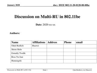
June 2020 doc.: 802.11-20/0562r5 Enhanced Multi-Link Single Radio Operation Date: 2020-6-4 Authors: Name Minyoung Park Affiliations Address Phone email Minyoung.park@intel.com Laurent Cariou Thomas Kenney Po-Kai Huang Intel Corporation Dibakar Das Dmitry Akhmetov Ehud Reshef Dan Bravo Submission Slide 1 Minyoung Park, Intel Corporation
June 2020 doc.: 802.11-20/0562r5 Introduction 11be non-AP MLDs are expected to have different capabilities for multi- link operation and many non-AP MLDs are expected to operate with a single radio It is important to enable a multi-link operation for a single radio non-AP MLD that can provide throughput enhancement and latency reduction close to a concurrent dual radio non-AP MLD In this presentation, we propose an enhanced multi-link single radio operation that can achieve this goal Submission Slide 2 Minyoung Park, Intel Corporation
June 2020 doc.: 802.11-20/0562r5 Problem: Multi-link operation using concurrent dual- radio in a busy network environment Reality: Channel 1 and Channel 2 busy (due to overlapping networks) Long delay if single radio Ideal case: Channel 1 and Channel 2 idle (no overlapping networks) AP AP STA STA (Concurrent dual radio) (Concurrent dual radio) (Concurrent dual radio) (Concurrent dual radio) data packet busy Radio 1 Radio 1 Radio 1 Radio 1 Channel 1 Channel 1 Low latency busy Radio 2 Radio 2 Radio 2 Radio 2 Channel 2 Channel 2 As network gets busier, there is less chance to have two (or multiple) idle channels at the same time In this case, most of time just one of the two channels will be used for data transfer This is effectively a single channel operation but switching between the two channels In a busy network, concurrent dual radio can still provide low latency benefit compared to single radio since AP can transmit a packet on any channel when the medium is idle Max peak throughput gain of concurrent dual radio can be achieved when two channels are idle In a busy network environment, concurrent dual-radio doesn t provide full benefit of STR Slide 3 Submission Minyoung Park, Intel Corporation
June 2020 doc.: 802.11-20/0562r5 Proposal: Enhanced Multi-link Single Radio (MLSR) Operation We propose an enhanced mode of operation for a single radio non-AP MLD where Single-radio non-AP MLD listens to two (or more) pre-configured channels simultaneously 2x2 Tx/Rx module may be configured to 1x1 on each channel/band (e.g. 5GHz and 6GHz) to listen to incoming packets on each channel 1x1 STA on one channel may add an extra 1x1 Rx on the other channel and listen to two channels for incoming packets AP MLD transmits a control frame (e.g. RTS or MU-RTS) on any idle channel of the pre-configured channels before a data frame transmission The control frame indicates to non-AP MLD which channel will be used for data transmission Upon reception of the control frame, non-AP MLD responds with a control frame (e.g. CTS) Data transmission follows the response from the non-AP MLD Non-AP MLD and AP MLD exchange frames on one link at a time Concurrent Dual Radio Proposal: Enhanced Multi-link Single radio STA AP Long delay if single radio AP STA Low latency (single radio) (Concurrent dual radio) (Concurrent dual radio) (Concurrent dual radio) R D busy D D D busy 1x1 Radio 1 1x1 on ch1 Radio 1 Radio 1 Radio 1 for data reception Channel 1 R A A Channel 1 Low latency C R 2x2 on ch2 1x1 Radio 1 1x1 on ch2 D D D D busy Radio 2 Radio 2 Radio 2 Channel 2 Channel 2 C C A Channel switch signal (RTS) Submission Slide 4 Minyoung Park, Intel Corporation
June 2020 doc.: 802.11-20/0562r5 Network Simulation Setup Configuration Target BSS: 4 OBSSs: OBSS traffic load on each band: 10-90% of 1x1, 80MHz, MCS0 PHY rate (36Mbps) on each band This is an example configuration that models channel occupancy due to OBSS (e.g. 10% load generates 3.6 Mbps traffic load and occupies approximately 10% of airtime) RTS/CTS enabled Comparisons: SLSR: Single-link, single-radio MLMR: Multi-link, multi-radio (concurrent) MLSR: Enhanced multi-link, single-radio (use RTS for channel switch signal) Throughput evaluation: Backlogged traffic on the target BSS (DL), simulation time: 10 sec, 6 times End-to-end latency evaluation: 512 byte packet every 20 msec, simulation time: 20 sec, 1 time 1 AP, 1 STA, 2 bands/channels 2x2, 80MHz, MCS0/4/7, max TXOP = 5msec 1 AP, 2 STAs each One STA on each band/channel 1x1, 80MHz, MCS0 Submission Slide 5 Minyoung Park, Intel Corporation
June 2020 doc.: 802.11-20/0562r5 Throughput results 80MHz, 2x2, MCS4 Enhanced multi-link single-radio achieves 60-70% throughput enhancement in a busy network (OBSS load : 40-70%) Enhanced multi-link single-radio reaches 70-80% of the multi-link multi-radio throughput in a busy network (OBSS load >30%) Submission Slide 6 Minyoung Park, Intel Corporation
June 2020 doc.: 802.11-20/0562r5 Throughput results for lower MCS 80MHz, 2x2, MCS0 Results follow similar trend as the MCS4 case Enhanced multi-link single-radio achieves 60-70% throughput enhancement in a busy network (OBSS load : 40- 70%) Enhanced multi-link single-radio reaches 70-80% of the multi-link multi-radio throughput in a busy network (OBSS load >30%) Submission Slide 7 Minyoung Park, Intel Corporation
June 2020 doc.: 802.11-20/0562r5 Throughput results for higher MCS 80MHz, 2x2, MCS7 Results follow similar trend as the MCS0 and MCS4 cases Enhanced multi-link single-radio achieves 60-70% throughput enhancement in a busy network (OBSS load : 40- 70%) Enhanced multi-link single-radio reaches 70-80% of the multi-link multi-radio throughput in a busy network (OBSS load >30%) Submission Slide 8 Minyoung Park, Intel Corporation
June 2020 doc.: 802.11-20/0562r5 Latency results In a very busy network, the proposed enhanced multi-link single radio approach reduces the end-to-end latency by half compared to single-link single radio worst case latency improvement The latency performance of the proposed method is similar to the multi- link multi-radio case 90%tile e2e latency measurement OBSS load 80% 90% SLSR 73ms 84ms ~half MLMR 32ms 38ms MLSR 32ms 39ms Submission Slide 9 Minyoung Park, Intel Corporation
June 2020 doc.: 802.11-20/0562r5 Enabling the proposed MLSR operation with minimal changes in 802.11be Non-AP MLD s behavior Indicates that it is Single-Radio non-AP MLD to its intended transmitter or receiver (i.e. AP MLD) Single-Radio non-AP MLD is unable to transmit or receive frames on more than one link simultaneously Enable two or more links Initial power states: one link is in the awake state and the rest are in the doze state Enable the dynamic SM power save for the two or more enabled link HE dynamic SM power save may need to be extended to EHT dynamic SM power save with additional constraints for the first frame of a frame exchange sequence E.g. the constraints of the first frame: supported MCS (up to MCS3-4), frame types (e.g. RTS, MU- RTS), PPDU type (e.g. non-HT PPDU) To enable the MLSR operation, the non-AP MLD indicates two or more enabled links are in the awake state (including the active mode) AP MLD s behavior When a non-AP MLD indicates the above information to the AP MLD, the AP MLD starts a frame exchange sequence by following the dynamic SM power save procedure on any one enabled link that is in the awake state (including the active mode) Slide 10 Submission Minyoung Park, Intel Corporation
June 2020 doc.: 802.11-20/0562r5 Conclusion When a single-radio non-AP MLD is operating in a busy network environment, having an additional capability to listen to two (or more) pre- configured channels simultaneously and an AP MLD able to deliver the non-AP MLD s queued data on the next pre-configured channel to become idle can provide most of benefits that can be provided by the multi-link operation of a concurrent dual-radio non-AP MLD Submission Slide 11 Minyoung Park, Intel Corporation
June 2020 doc.: 802.11-20/0562r5 Straw Poll 1 Do you agree to define Single-radio non-AP MLD as follows? Single-radio non-AP MLD: an MLD that transmits or receives frames on a single link to another MLD at a time Submission Slide 12 Minyoung Park, Intel Corporation
June 2020 doc.: 802.11-20/0562r5 Straw Poll 2 Do you support the concept of the multi-link operation for an enhanced single-link/radio (TBD) a non-AP MLD that is defined as follows for R1? An MLD that can: 1) transmit or receive data/management frames to another MLD on one link at a time, and 2) listening on one or more links. The listening operation includes CCA as well as receiving initial control messages (e.g., RTS/MU-RTS) The initial control message may have one or more additional limitations: spatial stream, MCS (data rate), PPDU type, frame type Link switch delay may be indicated by the non-AP MLD Submission Slide 13 Minyoung Park, Intel Corporation
June 2020 doc.: 802.11-20/0562r5 Straw Poll 3 Do you agree to defining capability/parameter exchange to enable the above enhanced single-link MLD operation and limitations? The exact method is TBD Submission Slide 14 Minyoung Park, Intel Corporation
June 2020 doc.: 802.11-20/0562r5 Straw Poll 4 Do you agree to indicate additional limitations for the first frame of a frame exchange sequence when it is operating as enhanced single-link MLD? The additional limitations are: spatial stream, MCS (data rate), PPDU type, frame type, link switch delay Note: Example:1 spatial stream, up to 24Mbps, transmitted in non-HT PPDU, only supports RTS/MU-RTS Submission Slide 15 Minyoung Park, Intel Corporation
June 2020 doc.: 802.11-20/0562r5 Appendix Submission Slide 16 Minyoung Park, Intel Corporation
June 2020 doc.: 802.11-20/0562r5 FAQs-1 [Q] The enhanced single-radio MLD does not seem to be a "single-radio" to me. [A] We called it single-radio since the MLD cannot operated on two links simultaneously as today s single link operation for 11ax. For example, the MLD cannot receive two data frames simultaneously and cannot transmit simultaneously. We agree that the naming might cause confusion so changing the name to enhanced single-link MLD could better describe such MLD. [Q] Your proposal is assuming an enhanced "single" radio with enhanced capability. My understanding is that it's more like two full front-end radios but an additional simplified digital backend (PHY and MAC) as minimum requirement. [A] We are assuming many single radio MLDs will be equipped with at least 2x2 MIMO capability and the idea is to reuse most of hardware that already exist in the single radio MLD for the proposed method but add extra capability to listen to two channels simultaneously. [Q] Based on slide 4, it seems to be dual-radio for control frames (e.g., RTS) (to be received on two links) and single-radio for data frames. However, the definition means receiving and transmitting (any) frames on a single link at a time. You mean the single-link MLD is only for data transmission? [A] We define a single radio MLD as an MLD that can transmit/receive frames on one link at a time. In our proposal, we are adding an extra capability to the single radio MLD that can perform CCA and receive limited type of packets (e.g. RTS in non-HT PPDU and low MCS) on two links simultaneously. This doesn t mean the AP MLD can transmit two RTS frames destined for the non-AP MLD on two links simultaneously. The AP MLD will transmit one RTS on one link that is idle since the AP MLD knows that the non-AP MLD is a single- radio MLD that can process a frame exchange sequence that will follow after the RTS. Processing the RTS frame that is transmitted with limitations such as non-HT PPDU type and low MCS just needs a fraction of the full receiver capability for processing any frame types transmitted in non-HT/HT/VHT/HE/EHT PPDU types, higher MCSs, and multiple spatial streams. Therefore we expect the enhanced single-radio MLD will have similar complexity as today s 11ax STA implementation but still benefit from multi-link operation. Slide 17 Submission Minyoung Park, Intel Corporation
June 2020 doc.: 802.11-20/0562r5 FAQs -2 [Q] Can STA receive and transmit at any link any time? [A] No. We assume the enhanced single-radio/link MLD listening to two links simultaneously but cannot Tx/Rx on any link at any time (e.g. no Tx/Tx, no Rx/Rx of any frames, no STR). The listening includes CCA and receiving only specific frames (e.g. control frame). [Q] You were assuming this minimum requirement only support some basic rate (like legacy OFDM rate, up to 24Mbps), and simple MAC format like RTS/CTS. My concern on this aspect is: how about trigger frame? they can be fairly complicated in terms of frame structure, and also processing delay for parsing etc. How about a few MCS rates since trigger frame and in particular MU-RTS as replacement of RTS for protection purpose for MU, can be transmitted by VHT or HE (supposed EHT as well) rate? [A] The first frame of a frame exchange sequence is limited to a control frame such as RTS/MU-RTS to address such complications or long processing delay. The first frame of a frame exchange sequence is also limited to use non-HT PPDU data rate up to 24 Mbps to manage the complexity. Other data rates/MCSs used in different PPDU types should be avoided to manage implementation complexity. [Q] Is there any radio or digital RX chain switch/tune time that needs to be considered to be practical? And if so, how much it would cost bandwidth/latency? [A] The time budget after the reception of the RTS frame until reception of the data frame following the CTS is around 100 microseconds so we don t see any issue in terms of switching/tune time. In case there is a long link switch time due to a certain vendor s implementation, link switch time could be added as a limitation of an MLD and indicate to the AP MLD and adjust its operation. [Q] You mentioned that the time budget is around 100uS after reception of RTS frame until reception of Data frame. But what about the CTS frame? The non-AP MLD needs to transmit the CTS on the new channel within SIFS of the RTS right? Or, are you assuming that being capable of listening on 2 links at a time, the non-AP MLD is also capable of transmitting basic frames (e.g. CTS) on both links at the same time? If not, the switch time available would be less than SIFS right? [A] The 100 usec time budget is for switching 1x1 rx on Link1 (channel1) to Link2 (channel2) so that 2x2 Rx can be used on Link2. For this, there is channel switching so needs some link switch delay and we believe this can be done in 100 usec. For a CTS transmission, since a CTS is transmitted on the link that RTS was received and there is no channel switching happening, we don't see any delay for the operation (maybe rx/tx turnaround time). Whether non-AP MLD needs to have CTS transmission capability on both links would be implementation dependent. As I noted above, adding link switch delay to indicate such limitation could be an option. Slide 18 Submission Minyoung Park, Intel Corporation
June 2020 doc.: 802.11-20/0562r5 FAQs-3 [Q] As this hopping of channel among multi-link is initiated by the AP en-powered by its assumed capability, AP is choosing channel according to its local CCA. But we know it's possible and non-trivial scenario where one channel/link is busy per the non-AP STA but not AP. The proposed mechanism would fail to handle this and the benefit diminishes (yet paid the cost of dual radio front-end.) Have you weighed in the cons or pros? [A] A data frame is transmitted on a link where RTS/CTS exchange between an AP MLD and a non-AP MLD was successful, which is same as how today s frame delivery is handled. If the RTS/CTS exchange is not successful due to channel busy on the non-AP STA side, the data frame is not transmitted. We are assuming at least 2x2 MIMO configuration for a single radio MLD and reusing the front-end hardware so there is no extra cost on the front-end side. [Q] If one channel is clean, what do we really gain from MLO/single radio (or even multiple radios)? [A] If one channel is clean and the other is busy then MLO in general doesn t help much since most of throughput will come from the clean channel. [Q] Does this limit to 20MHz only packets? [A] No, it is not limited to 20MHz. The supported bandwidth will depend on the non-AP MLD s capability as same as today s single link operation. For example, to reserve medium for 40MHz channel, RTS should be transmitted in 40MHz. [Q] The minimum required RX capability is 20MHz? [A] Yes, since the frame exchange sequence should start with an RTS in non-HT PPDU (simplest form). Submission Slide 19 Minyoung Park, Intel Corporation
June 2020 doc.: 802.11-20/0562r5 FAQs-4 [Q] This single radio actually is a single PHY, right? Assuming this single radio has multi-link RF chains, i.e. tx/rx and antenna. How does this single radio perform CCA when receiving multiple signals from different RF chains as those signals are mixed up in the PHY? [A] We define a single radio MLD as an MLD that can transmit/receive frame on one link at a time. In our proposal, we are adding an extra capability to the single radio MLD that can perform CCA and receive limited type of packets on two links simultaneously. Each RF chain will be connected to a separate PHY for independent signal processing (depends on implementation) but can just process limited type of packets. [Q] Can the enhanced single radio MLD device receive a 1x1 data frame on one link without RTS/CTS? (assuming no collision) [A] In this mode of operation, we assume the enhanced single radio MLD can listen (CCA) and only process limited PPDU type/frame type on both links simultaneously but cannot process data frame if received on the link that can just listen and process limited frames. However, if one link just has 1x1 limitation, and the other link has 1x1 and the all other limitations, 1x1 data frame may be received on the link that doesn t have the limitations. (we ll need to understand the complexity of such operation) [Q] Regarding the constraint of the enhanced single radio MLD that is not able to receive/transmit on both links. Are you assuming this constraint is dependent on the channel separation, BW and related parameters? Or, more of a RF path limitation of the enhanced single radio which will exist independent of BSS operation parameters? [A] The enhanced single radio constraint is independent of the BSS operation parameters. This can be viewed as the single-radio MLD similar to today s 11ax STA except it can utilize multiple links in a TDMA fashion. We are adding the extra capability on the single-radio MLD so that the MLD can listen to multiple links simultaneously. Submission Slide 20 Minyoung Park, Intel Corporation
June 2020 doc.: 802.11-20/0562r5 FAQs-5 [Q] My understanding is that enhanced single radio/link MLD can t receive any frames before it had received a limited control frames such as RTS/MU-RTS. This seems to be a weaker design as to its rx ability on each link. For example, in a typical deployment, both 11be clients and legacy clients are associated to a 11be AP. How does the enhanced single radio/link MLD set its NAV when legacy clients are communicating with AP? [A] In the enhanced single link MLD operation, an AP MLD, not non-AP MLD, initiates a frame exchange sequence by transmitting a control frame. Since the AP MLD is tracking NAV of both links, the frame exchange sequence initiated by the AP MLD doesn't have an issue accessing the medium and upon receiving the control frame from the AP MLD, the non-AP MLD exchanges frames with the AP MLD. This operation is similar to TWT operation where a STA waking up at the beginning of a TWT SP can access the medium once it receives a Trigger frame from the AP. For the non-AP MLD side, it is able to decode the legacy preamble and limited type of PPDU/frames so NAV can be set based on the PPDU/frame type it can decode and the Length field of the legacy preamble. Note that today a STA can set NAV if a received frame is decodable. For example VHT STA cannot set NAV if it receives HE PPDU or if MCS is too high causing packet error. Having said that, I think another possibility is one of the two links having full Rx capability (still 1x1) and the other link having rx limitation. [Q] How does the single radio/link MLD receive beacon frame and other management frames? Should a RTS frame be sent before beacon frames? [A] Beacon is transmitted at TBTT so a non-AP MLD can prepare for the beacon reception and doesn't need RTS. Other individually addressed management frames can be treated same as data frame. Submission Slide 21 Minyoung Park, Intel Corporation
June 2020 doc.: 802.11-20/0562r5 FAQs-6 [Comment] This is semi-finished product. I would like to have Multiple radio instead of enhanced single radio. Actually we do not have motivation to have it. We want to make ML framework simple. [Response] Whether to implement multi-radio based STR MLD or enhanced single radio is a choice of an implementer and the spec shouldn't exclude an option such as the enhanced single-link/radio that for some implementers give similar complexity compared to today's implementation but gives performance close to STR/non-STR implementation. For some implementers, there is a big complexity gap between today s 802.11 implementation and 802.11be (non)-STR MLD implementation and the enhanced single-radio operation could be a good solution to fill the gap in terms of complexity and performance. We can compare (1) today s typical single-radio/link (2x2 MIMO), (2) the proposed enhanced single-radio/link (2x2), (3) STR multi-radio (1x1 per link), and (4) STR multi-radio (2x2 per link) in terms of performance and complexity. (1), (2) and (3) have total two RF chains whereas (4) has four RF chains two RF chains on each link. STR multi-radio (3) and (4) have two 11be PHY blocks and two 11be MAC blocks independently operating for each link. (2) has one 11be PHY block (+ small non-HT PHY block) and one 11be MAC block (+ small MAC block (CCA and limited MAC frame processing)) In terms of complexity, (4) STR multi-radio (2x2 per link) is close to twice more complex than (1) single-radio (2x2 MIMO) and (2) enhanced single-radio (2x2). The complexity of (3) STR multi-radio (1x1 per link) is also much higher than (1) and (2) since it needs full-blown 11be PHY and MAC for each link independently. However, (3) STR multi-radio(1x1 per link) has similar throughput performance as (1), because (3) can just receive 1SS on each link. The throughput of (2) enhanced single-radio/link (2x2) is higher than (1) and (3) when wireless medium is moderate to busy due to OBSS. Therefore, (2) enhanced single-radio/link (2x2) is a good solution to fill the gap between today s (1) single-radio 2x2 MIMO and (4) STR multi-radio MLD (2x2 on each link) in terms of complexity and performance. (2) enhanced single-radio/link (2x2) is also better solution than (3) STR multi-radio MLD (1x1 per link) in terms of performance and complexity. Slide 22 Submission Minyoung Park, Intel Corporation