Inside the Circuitry of the Casio CTK-450 Electronic Keyboard
Detailed insights into the internal components of the Casio CTK-450 electronic keyboard, covering the power supply, CPU functionality, keyboard matrix circuit, filter block, and mute circuit. Explore how each element contributes to the overall functioning of the keyboard, from processing key presses to producing sound waveforms. Uncover the intricate circuit diagrams and technical specifications that drive this musical instrument.

Download Presentation

Please find below an Image/Link to download the presentation.
The content on the website is provided AS IS for your information and personal use only. It may not be sold, licensed, or shared on other websites without obtaining consent from the author. Download presentation by click this link. If you encounter any issues during the download, it is possible that the publisher has removed the file from their server.
E N D
Presentation Transcript
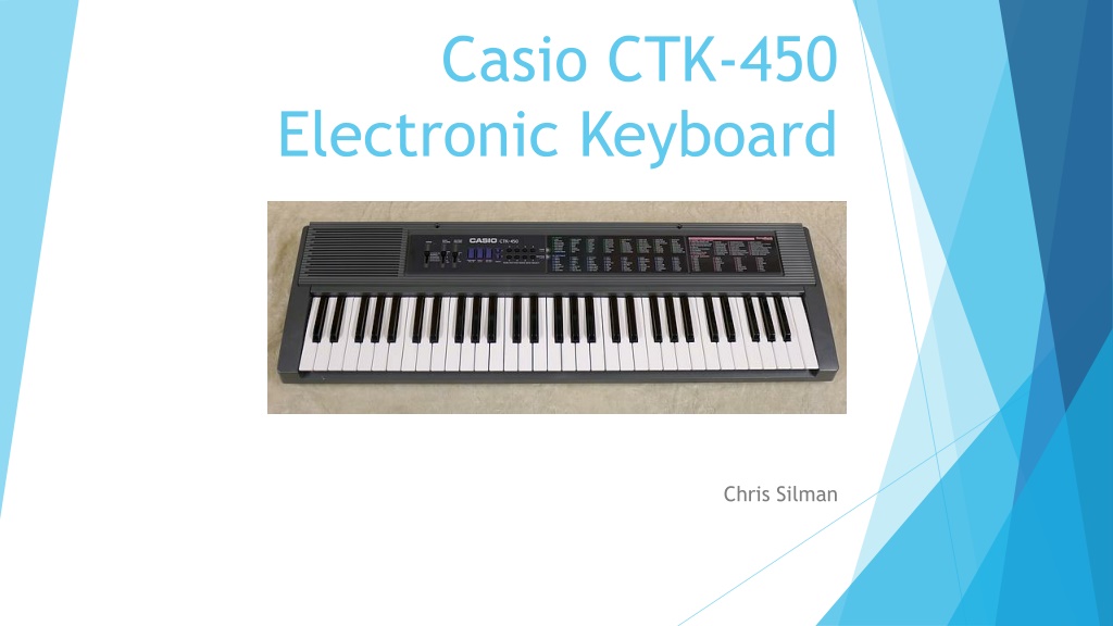
Casio CTK-450 Electronic Keyboard Chris Silman
Here on the left is a simple block diagram showing each key part that contributes to our keyboard. On the right is a technical representation of each component with circuit diagrams shown. As per the suggestion of Dr. Burns, we ll step through each component from the power supply all the way to the amplifier at the end.
Specifications Requires an AC adaptor/DC power source that will provide 9V. Requires 7.0 watts of power. Electrical specifications show current drain depending on what actions are being performed.
Power Supply The power supply circuit generates three voltages: VDD (+6.0V) for the CPU and Reset IC. AVDD (+6.0V) for Analog Circuit. (A stands for analog) VCC1 (+8.6V) for pilot lamp and power amplifier. While I couldn t find the exact circuit diagram for the AC/DC adaptor, I believe that this would closely resemble the one that would be used.
CPU and Keys On the right are shown all the pin specifications for our CPU. I couldn t find an exact circuit diagram, however, as seen in the picture above a bunch of wires are connected to a PCB under the piano keys. When a piano key is pressed, the CPU transforms that and produces a sound waveform. As you can see, it is not a smooth sinusoidal wave.
Why so few wires? How do we know what key? Uses something known as a keyboard matrix circuit . Essentially key switches are connected to a grid of wires. By scanning the crossing point of a row and column. With 16 wires we have up to 64 combinations. Notice how when a key is pressed, both a column and associated row have voltage passing. This is all processed by a keyboard controller (essentially informs CPU when key is pressed.).
Filter Block The sound signal from the CPU now enters our filter. As seen before, the CPU produces a stepped waveform and not a smooth sinusoidal signal. The purpose of the filter is to smooth out our waveform. Two BJTs can be see in the circuit diagram, T4 and T5. AVDD can be seen here too, which was +5v coming from our power supply.
Mute Circuit Shown to the left is a simple diagram of the mute IC The purpose of the mute circuit is to remove noise from the sound signal before it fades away. This circuit detects the amplitude of the decaying sound signal and amplifies it by 1000 times. The transistor T6 flows that signal into ground when amplitude decays to almost zero.
The Amplifier it all lead to here! Contains a two-channel power amplifier with stand-by switch, each channel having three op-amps with certain purposes. The purpose of the stand-by switch is when it receives +9V it is on, and at 0V it is off. Input Amp Broken into negative feedback input or just normal input Pre-drive Amplifier Converts weak electrical signal into an output signal strong enough to be noise- tolerant and used for further processing. Power Amplifier I couldn t find the circuit for the power amplifier, but I assume it would look somewhat similar to the image on the right. The transistor causes a certain amount of gain on our signal based on the resistor values (as seen in Lab 8!).
The Amplifier Info Cont. Here is a breakdown of all the pins that connect to our LA4598 audio amplifier.
Sources Casio CTK-450 Datasheet https://www.manualslib.com/manual/700162/Casio-Ctk-450.html#manual AC/DC Adaptor Circuit https://circuits-diy.com/9v-power-supply-circuit-using-lm7809-voltage-regulator-ic/ Internal Pictures https://www.deepsonic.ch/deep/htm/casio_ctk-450.php LA4598 Datasheet https://www.alldatasheet.com/datasheet-pdf/pdf/40126/SANYO/LA4598.html Keyboard Matrix Circuit https://en.wikipedia.org/wiki/Keyboard_matrix_circuit Keyboard Controller https://en.wikipedia.org/wiki/Keyboard_controller_(computing)