JCB VIBROMAX 752 Tandem Drum Roller Service Repair Manual Instant Download
Please open the website below to get the complete manualnn//

Download Presentation

Please find below an Image/Link to download the presentation.
The content on the website is provided AS IS for your information and personal use only. It may not be sold, licensed, or shared on other websites without obtaining consent from the author. Download presentation by click this link. If you encounter any issues during the download, it is possible that the publisher has removed the file from their server.
E N D
Presentation Transcript
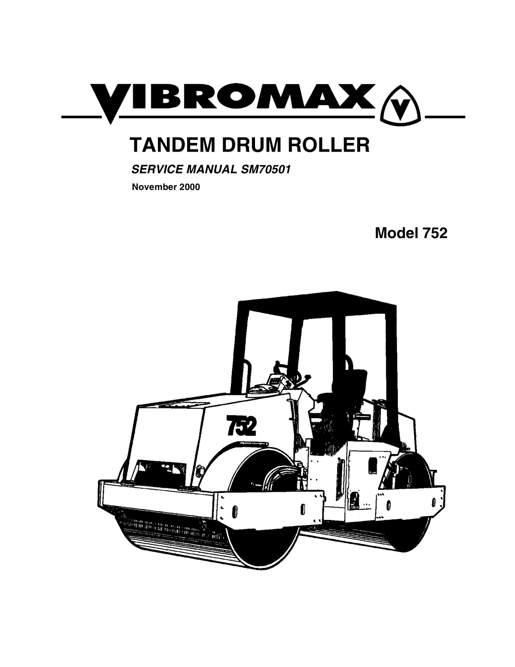
TANDEM DRUM ROLLER SERVICE MANUAL SM70501 November 2000 Model 752
CALIFORNIA Proposition 65 Warning Diesel engine exhaust and some of its constituents are known to the State of California to cause cancer, birth defects, and other reproductive harm.
table of contents SECTION ONE GENERAL INFORMATION MACHINE DESCRIPTION...............................................................................1 - 3 MACHINE SERIAL NUMBERS........................................................................1 - 5 IDENTIFYING MACHINE COMPONENTS......................................................1 - 6 MACHINE SPECIFICATIONS..........................................................................1 - 8 STANDARD TORQUE DATA................................................................... 1 - 10 FLUID CAPACITY - 752.................................................................................1 - 12 DIESEL FUEL SPECIFICATION....................................................................1 - 13 ENGINE OIL SPECIFICATION......................................................................1 - 14 ROLLOVER PROTECTION STRUCTURE ...................................................1 - 15 SAFETY, GENERAL......................................................................................1 - 16 SPARK ARRESTER................................................................................. 1 - 16 SAFETY, PERSONAL....................................................................................1 - 17 SAFETY, MACHINE OPERATION ................................................................1 - 19 SAFETY, MAINTENANCE.............................................................................1 - 22 SAFETY, DECALS.........................................................................................1 - 23 SECTION TWO ENGINE ENGINE DATA.................................................................................................2 - 2 CUMMINS ENGINE WARRANTY....................................................................2 - 3 ENGINE REMOVAL.........................................................................................2 - 4 SECTION THREE ELECTRICAL INSTRUMENT PANEL, RIGHT........................................................................3 - 2 INSTRUMENT PANEL, LEFT..........................................................................3 - 4 INSTRUMENT PANEL COVER.......................................................................3 - 5 COMBINATION INDICATOR...........................................................................3 - 6 SPEED RANGE CONTROL.............................................................................3 - 7 UNDERSTANDING ELECTRICAL SCHEMATICS........................................3 - 11 UNDERSTANDING RELAYS.........................................................................3 - 14 VIBROMAX RELAYS..........................................................................3 - 15 STARTER/CHARGING CIRCUIT ..................................................................3 - 17 UNDERSTANDING BATTERIES...................................................................3 - 17 BATTERY DIAGNOSTICS..................................................................3 - 18 UNDERSTANDING ALTERNATORS.......................................................3 - 19 CHARGING SYSTEM DIAGNOSTICS ...............................................3 - 20 VOLTAGE CHECKS AT ALTERNATOR.............................................3 - 21 SYSTEM LEAKAGE............................................................................3 - 21 I
table of contents CIRCUIT WIRING TEST .....................................................................3 - 21 MEASURING ALTERNATOR OUTPUT..............................................3 - 22 UNDERSTANDING STARTERS....................................................................3 - 22 STARTER SOLENOID........................................................................3 - 23 STARTER SYSTEM DIAGNOSTICS..................................................3 - 23 SOLENOID CIRCUIT TEST................................................................3 - 23 STARTER CIRCUIT WIRING TEST ...................................................3 - 24 STARTER MOTOR TEST...................................................................3 - 25 INSTRUMENTATION PANEL........................................................................3 - 27 LIGHTING CIRCUIT.......................................................................................3 - 29 WATER SPRINKLER CIRCUIT.....................................................................3 - 31 VIBRATION/DRUM SELECTION CIRCUITS.................................................3 - 33 VIBRATION CONTROL CIRCUIT..................................................................3 - 35 TWO SPEED PROPULSION MOTOR CIRCUITS.........................................3 - 37 WIRE CHART, RIGHT PANEL & HARNESS 4010/67455.............................3 - 44 WIRE CHART, LEFT PANEL & HARNESS 4010/67413...............................3 - 46 WIRE CHART, FRONT HARNESS 4010/67336............................................3 - 48 WIRE CHART, REAR HARNESS 4010/68335..............................................3 - 49 SECTION FOUR HYDRAULIC PROPULSION SYSTEM..................................................................................4 - 5 VIBRATION SYSTEM......................................................................................4 - 9 STEERING SYSTEM.....................................................................................4 - 13 BRAKE CIRCUIT ...........................................................................................4 - 17 HYDRAULIC AND COOLING LINES.............................................................4 - 18 HYDRAULIC DRAIN SYSTEM ......................................................................4 - 20 HYDRAULIC SYSTEM COMPONENTS........................................................4 - 22 PRESSURE TEST POINTS...........................................................................4 - 22 HYDRAULIC SCHEMATIC............................................................................4 - 23 SECTION FIVE POWER TRAIN 752 DRUM ASSEMBLY...................................................................................5 - 2 DRUM REMOVAL............................................................................................5 - 9 DRUM INSTALLATION..................................................................................5 - 10 DRUM DRIVE BEARING REMOVAL.............................................................5 - 11 DRUM DRIVE BEARING ASSEMBLY...........................................................5 - 13 DRUM DRIVE MOTOR REPAIRS .................................................................5 - 14 DRUM DRIVE GEARBOX..............................................................................5 - 15 GFT 17 T2/312 2 GEARBOX.........................................................................5 - 17 II
https://www.ebooklibonline.com Hello dear friend! Thank you very much for reading. Enter the link into your browser. The full manual is available for immediate download. https://www.ebooklibonline.com
table of contents SECTION SIX PARKING BRAKE SYSTEM BRAKE CIRCUIT .............................................................................................6 - 6 TOWING YOUR MACHINE .............................................................................6 - 7 SECTION SEVEN VIBRATION SYSTEM LIFTING DEVICE.............................................................................................7 - 2 DRUM EXCITER SHAFT.................................................................................7 - 3 752 VIBRATION SYSTEM...............................................................................7 - 4 VIBRATION SYSTEM......................................................................................7 - 7 VIBRATION FREQUENCY..............................................................................7 - 8 VIBRATION AMPLITUDE................................................................................7 - 9 VIBRATORY SYSTEM DIAGNOSTICS.........................................................7 - 10 752 DRUM DRAWING...................................................................................7 - 11 DRUM - LEFT SIDE.......................................................................................7 - 12 DRUM - RIGHT SIDE.....................................................................................7 - 15 DRUM REMOVAL..........................................................................................7 - 18 DRUM INSTALLATION..................................................................................7 - 19 RIGHT SIDE BEARING COVER....................................................................7 - 20 EXCITER BEARING REMOVAL....................................................................7 - 21 EXCITER BEARING ASSEMBLY..................................................................7 - 23 SECTION EIGHT STEERING SYSTEM STEERING SYSTEM.......................................................................................8 - 5 STEERING PIVOT REMOVAL ........................................................................8 - 6 STEERING CYLINDER..................................................................................8 - 10 SECTION NINE CHASSIS REAR ENGINE/ROLLER FRAME ...................................................................9 - 2 FRONT ROLLER FRAME................................................................................9 - 3 STEERING LINK..............................................................................................9 - 4 FRONT WATER/DIESEL TANK ......................................................................9 - 5 REAR WATER/HYDRAULIC TANK.................................................................9 - 6 INSTRUMENT CONSOLE...............................................................................9 - 7 SEAT RACK.....................................................................................................9 - 8 ROLLOVER PROTECTION STRUCTURE (ROPS) ........................................9 - 9 III
table of contents SECTION TEN ATTACHMENTS IV
SECTION ONE GENERAL INFORMATION 11/15/2000 1 - 1
SM70501 - SECTION ONE GENERAL INFORMATION 1 - 2 11/15/2000
SM70501 - SECTION ONE GENERAL INFORMATION MACHINE DESCRIPTION In the fall of 1999 Vibromax in- troduced the new 752 series tandem drum vibratory roller. The 752 has a significant im- provement in drive system. The operating weight is 18,728 lbs. (8,495 kg) while keeping the same 66 inch (1675mm) drum size. The roller uses the Cummins 3.9 liter 4 cylinder engine. The new engine is tuned to meet the latest emissions standards. A Mannesman Rexroth vari- able displacement, axial piston hydrostatic pump, used for machine propulsion, is mounted to the flywheel end of the engine. It provides oil to the front and rear drum drive motors in a parallel path. The Rexroth 2 speed drum drive motors are mounted on the left side of the drums, drive through L&S planetary gearboxes, and are isolated from the drum by rubber buffers. This arrangement is used in the heavy roller models with a great deal of success. These machines come standard with parking brakes at both the front drum and the rear drum. A spring applied-hydraulically released multi disc brake is part of the drum drive gearbox. The vibration system on the 752 uses a Rexroth hydrostatic pump mounted directly behind the propulsion pump. It is similar in design to the propulsion pump. The vibratory pump sup- plies oil to a Rexroth hydrostatic motor mounted at the right side of the drum. The new model 752 operates at frequencies of 2000 or 3000 vibrations per minute. Vibratory operations can be done with front drum only, both drums together, or rear drum only. 11/15/2000 1 - 3
SM70501 - SECTION ONE GENERAL INFORMATION A steering/charge pump, mounted to the auxiliary drive at the front of the engine, provides the oil needed for steering. The steering pump also acts as the charge pump in the propulsion/ vibration circuit. The steering pump draws oil from the reservoir, passes it through the steer- ing control valve, through the inline hydraulic filter, and into the charge circuit. The electrical system consists of a 12 volt battery, starter, alternator system, optional lighting and standard instrumentation. The model 752 comes standard with: Beveled drums - Dual scrapers on each drum - Automatic vibration off in neutral - Pressurized intermittent sprinkler system - Lockable instrument panel cover - Deluxe adjustable, 3 posi- tion operator s seat - Fuel level & engine temperature gauges - Hourmeter - Horn - Indicator lights for alternator charge, engine oil pressure, low water tank level and neutral position. Option equipment available: Gravity water sprinkler - Road lights - Front & rear halogen work lights - Speed limiter - Water level indicator gauge - Backup alarm - 4 post ROPS with canopy. 1 - 4 11/15/2000
SM70501 - SECTION ONE GENERAL INFORMATION MACHINE SERIAL NUMBERS Enter the machine and component serial numbers highlighted in the above drawing. When ordering spare parts or requesting information on the machine, have these numbers avail- able for your dealer. Make a copy of these numbers and keep it in a safe place. If the machine is stolen, these numbers should be made available to the investigating authorities. 1 2 3 4 5 6 7 Model / Serial Number Engine Serial Number ROPS Serial Number Front Drive Motor Serial Number Rear Drive Motor Serial Number Drive Pump Serial Number Vibration Pump Serial Number 11/15/2000 1 - 5
SM70501 - SECTION ONE GENERAL INFORMATION IDENTIFYING MACHINE COMPONENTS 1 rollover protection structure 6 dry air cleaner 2 front water tank 7 rear drive motor & gearbox 3 scraper 8 rear drum 4 front drive motor & gearbox 9 lifting and towing eye 5 front drum 1 - 6 11/15/2000
SM70501 - SECTION ONE GENERAL INFORMATION 1 hydraulic tank 6 fuel tank 2 rear water tank 7 front vibration motor 3 rear vibration motor 8 lifting and towing eye 4 engine 9 front water tank 5 radiator and oil cooler 11/15/2000 1 - 7
SM70501 - SECTION ONE GENERAL INFORMATION MACHINE SPECIFICATIONS MODEL 752 in. mm A 106 2690 B 77.6 1970 C 30.3 770 D 48 1220 H1 117 2970 H2 87 2210 K 10.6 270 L 166.5 4230 M 15.9 405 O 5.8 147.5 S 0.67 17 W 66 1675 E 40o 1 - 8 11/15/2000
Suggest: If the above button click is invalid. Please download this document first, and then click the above link to download the complete manual. Thank you so much for reading
SM70501 - SECTION ONE GENERAL INFORMATION ENGINE Make/Model/Type/Cooling Displacement - cu. in. (cc) HP, SAE net (kW) Operating speed - rpm. Air Cleaner Fuel Consumption- gal/hr (l/hr) Fuel capacity - gal (ltr) Electrical system Battery, amp hours/Alternator, amps Drive Propulsion Travel speed, 1st/2nd/3rd - mph (km/hr) Theoretical gradeability, forward -% Brakes, operating Brakes, parking Steering Articulation/Oscillation Operating Data Operating weight - lb (kg) Turning radius, inside - in (mm) Static linear drum load - lb/in (kg/cm) Cummins 4BT3.9C, Elite 4 cylinder diesel, water cooled 240 cu.in. (3920cc) 81hp (60kW) 2500 Dual replaceable elements 2.8 (10.5) 37 (140) 12-volt 120/65 Infinitely variable hydrostatic drive to both drums 0-2.4 (0-4) / 0-3.9 (0-6.3) / 0-7.4 (0-12) 40 Hydrostatic braking thru ground drive Spring applied hydraulic release on drum gearboxes Articulated, hydraulic powered 25/10 18,716 (8495) 200 (5080) front 136.7 (24.4) / rear 147 (26.4) Low frequency 2000 (33.3) .039 (1.0) 16,096 (7301) 244 (27.57) 0.67 (17) front 121.5 (460) / rear 95.1 (360) High frequency 3000 (50) .008 (.20) 7500 (3401) 113.5 (12.82) Frequency - vpm (Hz) Nominal amplitude - in (mm) Centrifugal force per drum - lb (kg) Centrifugal force/rolling width - lb/in. (Nm) Drum shell thickness - in (mm) Water tank capacity - gal (L) 11/15/2000 1 - 9
https://www.ebooklibonline.com Hello dear friend! Thank you very much for reading. Enter the link into your browser. The full manual is available for immediate download. https://www.ebooklibonline.com