JCB 444 Mechanical Engine Service Repair Manual Instant Download
Please open the website below to get the complete manualnn//

Download Presentation

Please find below an Image/Link to download the presentation.
The content on the website is provided AS IS for your information and personal use only. It may not be sold, licensed, or shared on other websites without obtaining consent from the author. Download presentation by click this link. If you encounter any issues during the download, it is possible that the publisher has removed the file from their server.
E N D
Presentation Transcript
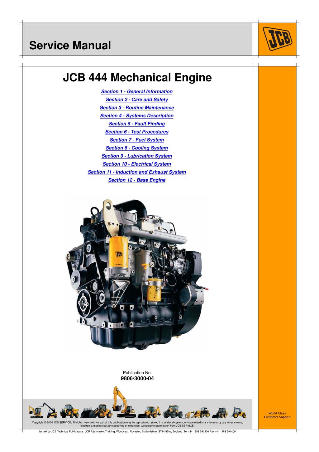
Service Manual JCB 444 Mechanical Engine Section 1 - General Information Section 2 - Care and Safety Section 3 - Routine Maintenance Section 4 - Systems Description Section 5 - Fault Finding Section 6 - Test Procedures Section 7 - Fuel System Section 8 - Cooling System Section 9 - Lubrication System Section 10 - Electrical System Section 11 - Induction and Exhaust System Section 12 - Base Engine Publication No. 9806/3000-04 World Class Customer Support Copyright 2004 JCB SERVICE. All rights reserved. No part of this publication may be reproduced, stored in a retrieval system, or transmitted in any form or by any other means, electronic, mechanical, photocopying or otherwise, without prior permission from JCB SERVICE. Issued by JCB Technical Publications, JCB Aftermarket Training, Woodseat, Rocester, Staffordshire, ST14 5BW, England. Tel +44 1889 591300 Fax +44 1889 591400
Section 0 - Service Manual Notes: 0-0 0-0 9806/3000-04
Section 1 General Information Service Manual - JCB 444 Mechanical Engine Section 1 - General Information Section 2 - Care and Safety Section 3 - Routine Maintenance Section 4 - Systems Description Section 5 - Fault Finding Section 6 - Test Procedures Section 7 - Fuel System Section 8 - Cooling System Section 9 - Lubrication System Section 10 - Electrical System Section 11 - Induction and Exhaust System Section 12 - Base Engine Publication No. 9806/3000-04 World Class Customer Support Copyright 2004 JCB SERVICE. All rights reserved. No part of this publication may be reproduced, stored in a retrieval system, or transmitted in any form or by any other means, electronic, mechanical, photocopying or otherwise, without prior permission from JCB SERVICE. Issued by JCB Technical Publications, JCB Aftermarket Training, Woodseat, Rocester, Staffordshire, ST14 5BW, England. Tel +44 1889 591300 Fax +44 1889 591400
https://www.ebooklibonline.com Hello dear friend! Thank you very much for reading. Enter the link into your browser. The full manual is available for immediate download. https://www.ebooklibonline.com
Section 1 - General Information Notes: 1-0 1-0 9806/3000-04
Section 1 - General Information Contents Contents Introduction About this Manual .................................................................................... 1 - 1 Using the Service Manual .................................................................. 1 - 1 Section Numbering ............................................................................. 1 - 1 Left Side, Right Side ........................................................................... 1 - 1 Units of Measurement ........................................................................ 1 - 1 Machine Related Data ........................................................................ 1 - 2 Acronyms and Abbreviations ................................................................... 1 - 3 Page No. Identifying the Engine Engine Identification Plate ....................................................................... 1 - 4 Engine Labels ..................................................................................... 1 - 4 Component Labels ............................................................................. 1 - 4 Engine Identification Number Explanation ......................................... 1 - 5 Engine Component Identification ............................................................. 1 - 6 Technical Data Basic Engine Data ................................................................................. 1 - 12 Engine Specifications ....................................................................... 1 - 12 Engine Block & Bedplate Data .............................................................. 1 - 14 Cylinder Head Data ............................................................................... 1 - 15 Inlet and Exhaust Valve Data ................................................................ 1 - 16 Rocker Levers, Rocker Shaft and Tappets Data ................................... 1 - 18 Pistons and Connecting Rods Data ....................................................... 1 - 19 Crankshaft Data ..................................................................................... 1 - 20 Camshaft Data ....................................................................................... 1 - 21 Fuel System Data .................................................................................. 1 - 22 Acceptable and Unacceptable Fuels ................................................ 1 - 22 Fuel Types ........................................................................................ 1 - 24 Usage and Effects of Fuels .............................................................. 1 - 25 Sulphur Content ............................................................................... 1 - 26 Effects of Fuel Contaminates ........................................................... 1 - 27 Lubrication System Data ....................................................................... 1 - 28 Cooling System Data ............................................................................. 1 - 29 Electrical Equipment Data ..................................................................... 1 - 30 Torque Settings Zinc Plated Fasteners and Dacromet Fasteners ................................... 1 - 32 Introduction ....................................................................................... 1 - 32 Bolts and Screws .............................................................................. 1 - 32 Hydraulic Connections ........................................................................... 1 - 36 'O' Ring Face Seal System ............................................................... 1 - 36 'Torque Stop' Hose System .............................................................. 1 - 39 Torque + Angle Explanation .................................................................. 1 - 40 Torque + Angle Tightening Procedure ................................................... 1 - 41 Engine Torque Figures .......................................................................... 1 - 42 Lubricants and Capacities Engine Lubricating Oil ........................................................................... 1 - 57 Recommended Oils .......................................................................... 1 - 57 Engine Oil Capacity .......................................................................... 1 - 57 Coolant Mixtures .................................................................................... 1 - 58 Service Aids Sealing, Retaining and Care Compounds ............................................. 1 - 59 1 - i 1 - i
Section 1 - General Information Contents Contents Service Tools General Engine Tools ............................................................................ 1 - 60 Specialist Engine Tools .......................................................................... 1 - 62 Service Tool Drawings ........................................................................... 1 - 67 892/01146 - Core Plug Fitting Tool ................................................... 1 - 67 892/01147 - Crankshaft Turning Tool ............................................... 1 - 68 892/01148 - Timing Pin ..................................................................... 1 - 69 892/01149 - Sump Sealant Template ............................................... 1 - 70 892/01150 - Oil Sump Location Dowel ............................................. 1 - 71 892/01151 - Injector Sleeve Removal Tool ....................................... 1 - 72 892/01152 - Valve Stem Seal Fitting Tool ......................................... 1 - 73 892/01154 - FIP Cover Removal Tool .............................................. 1 - 74 892/01155 - FIP Gear Removal Tool ................................................ 1 - 75 892/01157 - Crankshaft Front Seal Fitting Tool ................................ 1 - 76 892/01156 - Crankshaft Rear Seal Fitting Tool ................................. 1 - 77 892/01158 - Crankshaft Rear Seal Alignment Tool ........................... 1 - 78 892/01159 - Injector Seal Fitting Tool ............................................... 1 - 78 892/01168 - Dummy Injector ............................................................ 1 - 79 892/01169 - Top Dead Centre (TDC) Setting Tool ............................ 1 - 80 Engine Mounting Frame ................................................................... 1 - 81 Page No. Service Parts and Repair Kits Engine Repair Parts and Kits Identification ........................................... 1 - 82 Engine Lifting Lifting Information .................................................................................. 1 - 98 Operating Procedures Starting the Engine ................................................................................ 1 - 99 Pre-Start Notes ................................................................................. 1 - 99 Start Procedure .............................................................................. 1 - 100 Engine Checks After Start-up ......................................................... 1 - 101 Engine Running-in Procedure ........................................................ 1 - 102 Stopping the Engine ....................................................................... 1 - 103 1 - ii 1 - ii
Section 1 - General Information Introduction About this Manual Using the Service Manual Fault Finding ...etc. 5 Left Side, Right Side This publication is designed for the benefit of JCB Distributor Service Engineers who are receiving, or have received, training by JCB Technical Training Department. References to the `left' side and the `right' side of the engine are when viewed from the flywheel end of the engine, as shown at 1A. These personnel should have a sound knowledge of workshop practice, safety procedures, and general techniques associated with the maintenance and repair of engines. A Renewal of oil seals, gaskets, etc., and any component showing obvious signs of wear or damage is expected as a matter of course. It is expected that components will be cleaned and lubricated where appropriate, and that any opened hose or pipe connections will be blanked to prevent excessive loss of hydraulic fluid, engine oil and ingress of dirt. Finally, please remember above all else SAFETY MUST COME FIRST! The manufacturer's policy is one of continuous improvement. The right to change the specification of the engine without notice is reserved. No responsibility will be accepted for discrepancies which may occur between the specifications of the engine and the descriptions contained in this publication. Section Numbering The manual is compiled in sections, the first three are numbered and contain information as follows: General Information includes torque settings and service tools. 1 Care & Safety includes warnings and cautions pertinent to aspects of workshop procedures etc. 2 Routine Maintenanceincludes service schedules and recommended lubricants. 3 Fig 1. Units of Measurement The remaining sections deal with Descriptions, Fault Finding, Dismantling, Overhaul etc. of specific components, for example: In this manual, the S.I. system of units is used. For example, liquid capacities are given in litres. The imperial units follow in parenthesis () e.g. 28 litres (6 UK gal). 4 Systems Descriptions 1-1 1-1 9806/3000-04
Section 1 - General Information Introduction About this Manual Machine Related Data The JCB 444 Engine can be fitted to a variety of constructions and agricultural machines. The scope of this publication is limited to the engine, but references to a typical machine installation will be made. Tasks and information specific to a machine installation will be listed in the relevant machine Service Manual, for example engine removal and replacement procedures. 1-2 1-2 9806/3000-04
Section 1 - General Information Introduction Acronyms and Abbreviations Acronyms and Abbreviations Some of the following acronyms and abbreviations are used in this service manual. The remainder are used in the automotive industry and are repeated for reference only. Nm NSP O/D OEM PPM PSI PTO RH RME RPM SAE SME SOME STD TBA TC TCA TDC TI VOME Newton Metre Non Serviced Part Outside Diameter Original Equipment Manufacturer Parts per Million Pounds per square Inch Power Take Off Right Hand Rapeseed Methyl Ester Revolutions per Minute Society of Automotive Engineers Sunflower Methyl Ester Soyabean Methyl Ester Standard To be Advised Turbocharged Turbocharged Aftercooled Top Dead Centre Technical Information Vegetable Oil Methyl Esters C F A/R API BBDC BDC BSFC BTDC CCV CID CSA CSAS cST ECM ECS EPA ESOS Celsius Fahrenheit As Required American Petroleum Institute Before Bottom Dead Centre Bottom Dead Centre Brake Specific Fuel Consumption Before Top Dead Centre Crankcase Vent Cubic inch Displacement Cold Start Advance Cold Start Advance Solenoid Centistokes Electronic Control Module Emission Control System Environmental Protection Agency Electric Shut-Off Solenoid or Engine Shut- Off Solenoid Fatty Acid Methyl Esters Front End Accessory Drive Fuel Injection Equipment Fuel Injection Pump Mercury Horse Power Inside Diameter Kilogram Kilometres per hour Kilowatt Left Hand Litre Millimetre Miles per Hour Naturally Aspirated Not Applicable/Not Available FAME FEAD FIE FIP Hg HP I/D kg KPH Kw LH ltr mm MPH NA N/A 1-3 1-3 9806/3000-04
Section 1 - General Information Identifying the Engine Engine Identification Plate Engine Labels Each JCB 444 Engine has a unique identification number stamped onto the main engine block, as shown at 2A. Refer to K K Engine Explanation ( T T 1-5) for a full detailed description of the number. Identification Number In addition to the identification number, there is an emisssions legislation label 2B. Component Labels In addition to the engine labels, some of the machine engine components will also have a label attached, or a part number etched into the casting, these include: the starter motor the alternator the fuel injection pump engine bedplate engine block cylinder head Turbo charger In some instances, it may be necessary to quote the information on these labels, for instance if there is a parts query, or a warranty claim. Make a note of these numbers. Fig 2. 1-4 1-4 9806/3000-04
Section 1 - General Information Identifying the Engine Engine Identification Plate Engine Identification Number Explanation The full engine number is stamped on the emissions label and the serial number is stamped on the engine block. K K Fig 2. ( T T 1-4). An explanation of the full engine number is detailed below. K K Fig 4. ( T T 1-5). If you need parts or service information for your engine, you must quote the complete engine number. Fig 3. SA 320/40001 U 00001 04 4.4 Litre Engine Family: SA = Naturally Aspirated SB = Turbocharged SC = Turbocharged and Intercooled SD = Turbocharged SF = Turbocharged and Intercooled Engine Part Number Country of manufacture: U = United Kingdom Engine Serial Number Year of manufacture Fig 4. 1-5 1-5 9806/3000-04
Section 1 - General Information Identifying the Engine Engine Component Identification Engine Component Identification Table 1. Engine - As viewed on the left hand side. 12 13 14 15 16 17 18 19 20 21 22 K K Fig 5. ( T 1 Rocker cover 2 Fuel injectors and high pressure fuel pipes 3 Lubrication oil filler cap 4 Timing gear case 5 Flywheel housing 6 Bed plate 7 Lubrication oil pan (sump) 8 Engine lifting eye 9 Air Inlet manifold 10 Fuel injection pump 11 Fuel lift pump T 1-7) Fuel filter Lubrication oil filler cap Lubrication oil filter Lubrication oil cooler housing Lubrication oil dip stick Low duty PTO (blanking cover if no device is fitted) Water temperature sender (cold start) Low pressure fuel line (to tank) Oil drain plug (sump) Oil pressure switch Inlet manifold induction heater (if fitted) 1-6 1-6 9806/3000-04
Section 1 - General Information Identifying the Engine Engine Component Identification 22 3 2 2 2 2 1 9 8 10 18 14 4 5 15 13 21 19 16 17 6 20 12 7 11 Fig 5. SB Type engine shown 1-7 1-7 9806/3000-04
Section 1 - General Information Identifying the Engine Engine Component Identification Table 2. Engine - As viewed on the right hand side K K Fig 6. ( T 1 Rocker cover 2 Breather chamber inspection cover 3 Cylinder block 4 Timing gear case 5 Flywheel housing 6 Bed plate 7 Lubrication oil pan (sump) 8 Lifting eye 9 Turbocharger (turbocharged engine only) 10 Turbocharger waste gate actuator assembly T 1-9) 11 12 13 14 15 16 17 18 19 20 Exhaust manifold Alternator and drive pulley assembly (belt not fitted) Coolant pump drive pulley (belt not fitted) Coolant pump housing (cylinder block) Coolant inlet/radiator hose connector Heavy duty PTO (blanking cover if no device is fitted) Starter motor assembly Turbocharger oil drain line (turbocharged engine only) Turbocharger oil feed line (turbocharged engine only) Oil drain plug (sump) 1-8 1-8 9806/3000-04
Section 1 - General Information Identifying the Engine Engine Component Identification 8 2 10 9 1 11 3 4 12 13 14 16 19 15 5 6 20 17 7 18 Fig 6. SB Type engine shown 1-9 1-9 9806/3000-04
Section 1 - General Information Identifying the Engine Engine Component Identification 15 14 13 1 2 11 12 8 7 9 10 3 4 6 5 Fig 7. SB Type engine shown Table 3. Engine - As viewed on the crankshaft pulley (front) end K K Fig 7. ( T 1 Rocker cover 2 Cylinder head 3 Cylinder block 4 Bed plate 5 Lubrication oil pan (sump) 6 Crankshaft pulley 7 Front end accessory drive belt T 1-10) 9 10 11 12 13 14 15 Drive belt tensioner and pulley Coolant pump and drive pulley assembly Idler pulley Alternator and drive pulley assembly Cab heater water hose connector Coolant temperature sender Coolant thermostat housing/radiator hose connector 8 Idler pulley 1-10 1-10 9806/3000-04
Section 1 - General Information Identifying the Engine Engine Component Identification 1 2 5 4 3 Fig 8. SB Type engine shown Table 4. Engine - As viewed on the flywheel (rear) end K K Fig 8. ( T 1 Rocker cover 2 Cylinder head 3 Flywheel T 1-11) 4 5 Fuel injection pump drive gear cover Flywheel housing 1-11 1-11 9806/3000-04
Section 1 - General Information Technical Data Basic Engine Data Technical Data Basic Engine Data Engine Specifications Engine Type: - SA - SB - SC - SD - SF Rated speed Weight (Dry): - SA - SB, SC, SD, SF Number of cylinders Nominal bore size Stroke Cylinder arrangement Combustion Cycle Firing order Displacement Compression ratio - SA - SB - SC - SD, SF Engine Compression Naturally Aspirated Turbocharged Turbocharged with Intercooler Turbocharged Turbocharged with Intercooler 2200 rpm 472 kg (1040 lb) 477 kg (1052 lb) 4 103 mm (4.055 in) 132 mm (5.16 in) In line 4-stroke 1-3-4-2 4.40 litres 18.6 : 1 18.3 : 1 17.5 : 1 17.2 : 1 see Note (1) Clockwise 4 per cylinder Direction of rotation (viewed from front {crankshaft pulley} end) Valves Valve tip clearances (measured cold): - SA, SB, SC Inlet: 0.19 to 0.27 mm (0.007 to 0.011 in) Exhaust: 0.56 to 0.64 mm (0.022 to 0.025 in) Inlet: 0.35 mm (0.014 in) Exhaust: 0.56 to 0.64 mm (0.022 to 0.025 in) - SD, SF Lubricating oil pressure (2) Combustion system 4.0 to 4.8 bar (58 to 70 lb in2) Direct Injection 1-12 1-12 9806/3000-04
Section 1 - General Information Technical Data Basic Engine Data Fuel injection pump Rotary Mechanical (1) (2) Compression variance between each cylinder should be no greater than 3.5 bar (50 lb in2) Engine at normal operating temperature and maximum revs. 1-13 1-13 9806/3000-04
Section 1 - General Information Technical Data Engine Block & Bedplate Data Engine Block & Bedplate Data 103.000 to 103.020 mm (4.055 to 4.046 in) Cylinder bore (1) Main bearing bolts torque (2) - first stage - second stage - final stage Surface finish for cylinder head joint Diameter of first oversize bore Diameter of second oversize bore Main bearing bore (without bearings) - numbers 1 to 4 - number 5 Main bearing bore (with bearings) - numbers 1 to 4 - number 5 Camshaft bore - numbers 1 to 4 50 Nm (37 lbf ft) 115 Nm ( 85 lbf ft) turn a further 180 Rz < 15um; Rmax < 20um 103.500 to 103.520 mm (4.074 to 4.076 in) 104.00 to 104.020 mm (4.094 to 4.952 in) 92.000 to 92.020 mm (3.622 to 3.623 in) 105.000 to 105.020 mm (4.134 to 4.135 in) 88.047 to 88.090 mm (3.466 to 3.468 in) 100.047 to 100.090 mm (3.939 to 3.941 in) 60.040 to 60.070 mm (2.364 to 2.365 in) 60.290 to 60.32 mm (2.374 to 2.375 in) - number 5 (bush) (3) Permissible wave profile wt<10m (2.5 distance) (1) (2) Nominal diameter to be measured 63mm below head face. Torque information MUST be used in conjunction with recommended procedures contained in this manual. Failure to use the appropriate and correct removal, replacement, dismantle and assembly procedures may result in an engine failure in service. Refer also to the procedures for the correct bolt tightening sequence. Bush no longer fitted from January 2008. (3) 1-14 1-14 9806/3000-04
Section 1 - General Information Technical Data Cylinder Head Data Cylinder Head Data Cylinder head distortion (maximum permissible) - end to end - side to side Valve recess depth - Inlet - Exhaust Valve seat angle - inlet - exhaust 0.05 mm (0.002 in) 0.03 mm (0.0012 in) 0.85 mm (0.033 in) 0.85 mm (0.033 in) 120 (inclusive) 90 (inclusive) Cylinder head bolts torque (1) - first stage - second stage - third stage - fourth stage - final stage Surface finish for cylinder head joint Permissible wave profile 40 Nm (30 lbf ft) 75 Nm (56 lbf ft) repeat 75 Nm torque angle + 90 torque angle + 180 Rz < 15um; Rmax < 20um wt < 10um 2.5 distance (1) Torque information MUST be used in conjunction with recommended procedures contained in this manual. Failure to use the appropriate and correct removal, replacement, dismantle and assembly procedures may result in an engine failure in service. Refer also to the procedures for the correct bolt tightening sequence. 1-15 1-15 9806/3000-04
Section 1 - General Information Technical Data Inlet and Exhaust Valve Data Inlet and Exhaust Valve Data Max lift inlet - SA, SB, SC - SD, SF Max lift exhaust - SA - SB, SC - SD, SF Inlet opens (top of ramp) - SA, SB, SC - SD, SF Inlet closes - SA, SB, SC - SD, SF Exhaust opens - SA - SB, SC - SD, SF Exhaust closes - SA, SB, SC - SD, SF Valve stem diameter - SA, SB, SC 9.37 mm @ 101 atdc 9.64 mm @ 101 atdc 9.42 mm @ 110 btdc 9.42 mm @ 115 btdc 9.84 mm @ 115 btdc 10 btdc 6 btdc 32 abdc 28 abdc 50 bbdc 60 bbdc 41 bbdc 10 atdc 9 atdc Inlet: 6.935 +/-0.0075 mm (0.273 +/-0.0003 in) Exhaust: 6.975 +/-0.0075 mm (0.275 +/-0.0003 in) Inlet: 6.928 to 6.943 mm (0.2727 to 0.2733 in) Exhaust: 6.918 to 6.933 mm (0.2724 to 0.2729 in) 40.18 mm (1.581 in) - SD, SF Valve spring free length Valve guide bore diameter - min - max Valve face angle - inlet - exhaust Valve length Valve sealing Valve head depth (below cylinder head surface) - inlet 6.958 mm (0.2739 in) 6.968 mm (0.2743 in) 60.5 45.17 131.9 to 132.4 mm (5.193 to 5.213 in) stem seal with sealing washer 0.89 to 1.39 mm (0.035 to 0.055 in) 1-16 1-16 9806/3000-04
Section 1 - General Information Technical Data Inlet and Exhaust Valve Data - exhaust 0.95 to 1.45 mm (0.037 to 0.057 in) 2.98 to 3.38 mm (0.117 to 0.133 in) Valve rim thickness 1-17 1-17 9806/3000-04
Suggest: If the above button click is invalid. Please download this document first, and then click the above link to download the complete manual. Thank you so much for reading
Section 1 - General Information Technical Data Rocker Levers, Rocker Shaft and Tappets Data Rocker Levers, Rocker Shaft and Tappets Data Valve tip clearances (measured cold): - SA, SB, SC Inlet: 0.19 to 0.27 mm (0.007 to 0.011 in) Exhaust: 0.56 to 0.64 mm (0.022 to 0.025 in) Inlet: 0.35 mm (0.014 in) Exhaust: 0.56 to 0.64 mm (0.022 to 0.025 in) - SD, SF Rocker lever bore diameter - min - max Rocker shaft diameter - min - max Tappets stem diameter - min - max Tappet bore diameter - min - max Tappet height (maximum) 26.046 mm (1.025 in) 26.129 mm (1.029 in) 26.00 mm (1.0236 in) 26.021 mm (1.0244 in) 19.987 mm (0.787 in) 19.975 mm (0.786 in) 20.00 mm (0.7874 in) 20.021 mm (0.7882 in) 55.25 mm (0.0218 in) 1-18 1-18 9806/3000-04
https://www.ebooklibonline.com Hello dear friend! Thank you very much for reading. Enter the link into your browser. The full manual is available for immediate download. https://www.ebooklibonline.com