NNbar Annihilation Detector Mechanical Design Proposal
NNbar Annihilation detector:
mechanical design
Sam Silverstein
Stockholm University
The usual disclaimers…
•
This is an initial, incomplete proposal for how to build NNbar
•
Critiques and alternative ideas are warmly welcomed
•
More information is needed to flesh out the design ideas
•
Dimensions, weights, requirements for cabling and other services, etc…
•
I hope this can start a wider discussion within the collaboration
•
I am not an engineer
•
My ideas are based on “back of the envelope” calculations
•
A real engineer should check the numbers before taking them further
“Ideal” annihilation detector
(from
Symmetry
article)
Some practical concerns….
LEC
: pointing geometry for
LG blocks requires an intricate
support structure and a painstaking
installation procedure.
Scintillator modules
: SiPMs and electronic
are mounted at the end of every stave,
as well as cables that must be routed off
the detector.
TPC modules
: need
space for services
(power, HV, gas, readout,
cooling, etc.)
Other practical concerns:
•
Support structure
•
Need to stably support a very heavy detector
•
~100 tons of lead glass
•
~ 30 tons of plastic scintillator
•
Minimize gaps and dead material
•
Provide safe access for maintenance/repair
•
Services
•
Provide “gaps” for routing cables and services to inner detector systems
•
While maintaining angular coverage
•
Space for installing on- or near-detector electronics (such as digitizers)
•
Installation
•
Can we feasibly build and install the detector as designed at ESS?
Proposed changes to the baseline design
HRD:
Monolithic top/bottom/sides to reduce
coverage gaps (and number of r/o channels)
LG ECal:
Modular installation of LEC blocks
in a non-pointing arrangement
Wider gaps at endcap regions
Accessibility and services
to the TPC and HRD, and room for
beam tube support (if needed)
*I will not cover the
silicon tracker in
this talk…
Gaps between LEC sections
power and readout connections
to HRD front-end electronics
Pb glass (LEC)
top/bottom: ~23 tons
2.04 x 0.85 x 2m
1.87 x 0.85 x 2m
1.87 x 0.85 x 2m
1.87 x 0.85 x 2m
1.87 x 0.85 x 2m
2.04 x 0.85 x 2m
0.3 x 3.74 x 4m
Scintillator (HRD):
~5.3 tons / side
0.3 x 4.4 x 4m
Scintillator (HRD)
top/bottom: ~4.5 tons
Central detector
End caps
0.3 x 1.15 x 3.2m
0.3 x 1.15 x 3.2m
0.3 x 1.15 x 3.2m
0.3 x 1.15 x 3.2m
0.2 x 4.5 x 4
0.2 x 4.5 x 4
0.2 x 5 x 5.5
0.2 x 5 x 5.5
Pb glass (LEC):
~15 tons /side
Material densities:
Polystyrene (scintillator) ~1 g/cm3
Pb glass: ~4.1 g/cm3
Aluminium: 2.375 g/cm3
Scintillator (HRD):
endcap ~4.4 tons
(1.1 tons/quadrant
)
Pb glass (LEC)
~ 8.4 tons/endcap
0.2 x 1.45 x 5m
0.2 x 1.45 x 2.1m
0.2 x 1.45 x 2.1m
0.2 x 1.45 x 5m
0.3 x 4.4 x 4m
0.3 x 3.74 x 4m
Note: HRD endcap quadrants
have SiPMs / FE electronics
at “outside” edges only.
2.04 x 0.85 x 2m
0.3 x 4.4 x 4m
0.3 x 4.4 x 4m
2.04 x 0.85 x 2m
2.04 x 0.85 x 2m
2.04 x 0.85 x 2m
0.2 x 5 x 5.5
0.2 x 5 x 5.5
TPC chambers:
”light”
Assume a rack-like support
structure around the beam pipe
How much do the detector pieces weigh?
Al Beam pipe
~300 kg/meter (with 2cm thickness)
or ~1.8 tons in the detector volume
EM calorimeter (LEC)
An LEC glass counter
LG block
40mm x 40mm x 200mm ZF2 (SF5)
wrapped with specular reflective
film and opaque tape
Mounting flange
Martensitic stainless steel
Diffuser
3mm white acrylic
Light guide
Mirror coated clear acrylic
SiPM with pre-amplifier board
12mmx12mm Hamamatsu
Modular assembly of 16 (4x4) LG counters
H beam: W100x100mm
9.5 cm
10 cm
20 cm
~17 cm
rollers
Alignment/tightening screws
Cooling water
Cable channel
ADC & readout board
Front-end boards
LEC mechanics
(top orientation*)
* proposed side- and
and bottom- orientations
in the following slides
Cable
(Mini HDMI)
“Bracket”
Standoff plates
rollers
Alignment/tightening screws
Cooling water
Cable channel
F/E boards
LEC mechanics
(bottom orientation)
“bracket” is longer than the
top version in order to
make room for the rollers:
Top
Bottom
LEC mechanics
(side orientation)
roller
roller
Asymmetrical “bracket”
for horizontal support
and alignment
Rear access to
LEC electronics
~7 cm gaps between
H beams allow access
to cable connectors on
the SiPM/preamplifier
front-end boards
H-beam
~7cm
H-beam
10 cm
10 cm
HRD (scintillating staves)
Installation strategy for HRD
•
All four sides of a (central) HRD section are instrumented and cabled
•
This favors a design with large-area sections to avoid coverage gaps
•
This also means that the HRD cannot be supported or rest on any side.
•
Proposed solution:
•
Glue scintillating staves together into large ”Monolithic” HRD sections
•
Use thin steel cables to hang top/side HRD sections from overhead beams
•
Install the bottom HRD section on a platform above the bottom LEC layer.
Supporting the HRD scintillators
0.3 x 3.74 x 4m
0.2 x 4.5 x 4
0.2 x 4.5 x 4
0.2 x 5 x 5.5
0.3 x 3.74 x 4m
0.2 x 5 x 5.5
0.2 x 5 x 5.5
0.3 x 4.4 x 4m
Bottom HRD supported
by a
platform
Top and side HRD suspended by steel cables from top H-beam
Top HRD
suspended
by 2.5mm diam.
steel cables from top H-beams.
These cables must pass through the
LG detector, requiring slightly wider
“gaps” between some LG rows
(e.g. ~6mm instead of 2.5mm)
Bottom HRD
can be supported by
a
platform
of low-density material
(carbon composite?).
Platform supported from bottom
H-beams through gaps in LG layer.
Platform supports
Side HRDs
suspended
from
top H-beams by 2.5mm cables.
Each cable passes through the
HRD from front to back
Top cables pass through the HRD
to support “anchors” below
Steel suspension cables:
2mm: up to ~230 kg,
2.5mm: up to ~430kg
,
Passing cables through the HRD
Horizontal and vertical staves bonded
together with glue or double-sided tape
Steel cable
2 - 2.5 mm
5mm steel tube
5mm “gaps” between staves around
hanging points
Beam tube
Supporting the beam tube inside the
experiment
Beam tube (2cm Al)
Circular rib (steel)
Maintains shape and
provides attachment points
Possible support point locations
NNbar support structure
NNBar support structure requirements
•
Steel support structure
•
Attachment points for horizontal LEC support H-beams
•
Hanging points for top-and side HRD sections
•
Resting point for bottom HRD section
•
Horizontal & diagonal braces for stability/rigidity
•
Concrete shielding
•
2m thick shielding blocks for radiation protection and cosmic shielding
•
Cosmic veto detector installed on inner wall
•
Working platforms and ladders
•
Safe access to all areas of the detector
2.04 x 0.85 x 2m
1.87 x 0.85 x 2m
1.87 x 0.85 x 2m
1.87 x 0.85 x 2m
1.87 x 0.85 x 2m
2.04 x 0.85 x 2m
0.3 x 3.74 x 4m
0.3 x 4.4 x 4m
Cross section around target
0.2 x 4.5 x 4
0.2 x 4.5 x 4
0.2 x 5 x 5.5
0.3 x 3.74 x 4m
0.2 x 5 x 5.5
0.2 x 5 x 5.5
0.3 x 4.4 x 4m
Horizontal support beams
W10x22 (W230x32.7)
26 cm h, 14.6 cm w
Tweb: 6.1 mm
Vertical supports
RHS 300 x 200 mm
(10mm thickness)
2.04 x 0.85 x 2m
0.3 x 4.4 x 4m
0.3 x 4.4 x 4m
2.04 x 0.85 x 2m
2.04 x 0.85 x 2m
2.04 x 0.85 x 2m
0.2 x 5.5 x 4
0.2 x 5.5 x 4
Cross section along center line
LEC support beams
W100x100mm
9,5 cm h, 10 cm w
Tweb: 9 mm
0.2 x 1.45 x 3.5m
0.2 x 1.45 x 3.2m
0.2 x 1.45 x 3.5m
0.2 x 1.45 x 3.5m
End cap (LEC support)
~125 cm
2
1.87 x 0.85 x 2m
0.3 x 4.4 x 4m
0.3 x 4.4 x 4m
1.87 x 0.85 x 2m
1.87 x 0.85 x 2m
1.87 x 0.85 x 2m
0.2 x 5.5 x 4
0.2 x 5.5 x 4
2.04 x 0.85 x 2m
2.04 x 0.85 x 2m
0.3 x 3.74 x 4m
Top view
Horizontal braces
2.04 x 0.85 x 2m
1.87 x 0.85 x 2m
1.87 x 0.85 x 2m
1.87 x 0.85 x 2m
1.87 x 0.85 x 2m
2.04 x 0.85 x 2m
0.3 x 3.74 x 4m
0.3 x 4.4 x 4m
0.2 x 4.5 x 4
0.2 x 4.5 x 4
0.2 x 5 x 5.5
0.3 x 3.74 x 4m
0.2 x 5 x 5.5
0.2 x 5 x 5.5
0.3 x 4.4 x 4m
Horizontal support beams
W10x22 (W230x32.7)
26 cm h, 14.6 cm w
Tweb: 6.1 mm
Vertical supports
RHS 300 x 200 mm
(10mm thickness)
LEC support beams
W100x100mm
9,5 cm h, 10 cm w
Tweb: 9 mm
Platform supports for
bottom HRD section
(custom)
Cross section around target
Cosmic veto layer
Diagonal
braces
Working platforms,
steps
Concrete shield
2m thick
0.2 x 1.45 x 3.5m
0.2 x 1.45 x 3.2m
0.2 x 1.45 x 3.5m
0.2 x 1.45 x 3.5m
Horizontal support beams
W10x22 (W230x32.7)
26 cm h, 14.6 cm w
Tweb: 6.1 mm
Vertical supports
RHS 300 x 200 mm
(10mm thickness)
LEC support beams
W100x100mm
9,5 cm h, 10 cm w
Tweb: 9 mm
Platform supports for
bottom HRD section
(custom)
Cross section around endcap
Cosmic veto layer
Diagonal/
horizontal
braces
Working platforms,
steps
Concrete shield
2m thick
2.04 x 0.85 x 2m
2.04 x 0.85 x 2m
Horizontal support beams
W10x22 (W230x32.7)
26 cm h, 14.6 cm w
Tweb: 6.1 mm
Vertical supports
RHS 300 x 200 mm
(10mm thickness)
LEC support beams
W100x100mm
9,5 cm h, 10 cm w
Tweb: 9 mm
Platform supports for
bottom HRD section
(custom)
Side view
Cosmic veto layer
Working platforms,
steps
Concrete shield
2m thick
0.3 x 4.4 x 4m
0.3 x 4.4 x 4m
2.04 x 0.85 x 2m
2.04 x 0.85 x 2m
0.2 x 5.5 x 4
0.2 x 5.5 x 4
Diagonal/
horizontal
braces
Summary
•
Main features of the proposed design
•
LEC arranged in modular sections (17cm x17cm) installed on horizontal H-
beams
•
HRD in large monolithic sections
•
Top and sides suspended from thin steel cables
•
Bottom secton supported by a platform
•
Beam tube can be suspended within the detector volume if needed
•
Cosmic veto mounted on insides of concrete enclosure.
•
Still to be added to the design
•
Support structure for the TPC chambers
•
Si tracker cabling and services
•
I did not cover the installation plan in this talk
•
I believe it is possible to install the detector as described here
•
But it will require careful planning and scheduling!
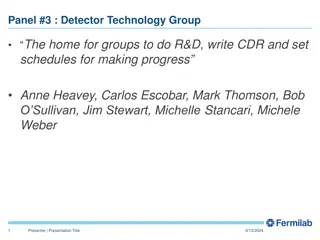
This proposal outlines the mechanical design considerations for the NNbar Annihilation Detector, highlighting practical concerns and proposed changes to the baseline design. Topics cover the structure support, component weights, installation challenges, and optimizations for improved detector performance.

Download Presentation

Please find below an Image/Link to download the presentation.
The content on the website is provided AS IS for your information and personal use only. It may not be sold, licensed, or shared on other websites without obtaining consent from the author. Download presentation by click this link. If you encounter any issues during the download, it is possible that the publisher has removed the file from their server.
E N D
Presentation Transcript
NNbar Annihilation detector: mechanical design Sam Silverstein Stockholm University
The usual disclaimers This is an initial, incomplete proposal for how to build NNbar Critiques and alternative ideas are warmly welcomed More information is needed to flesh out the design ideas Dimensions, weights, requirements for cabling and other services, etc I hope this can start a wider discussion within the collaboration I am not an engineer My ideas are based on back of the envelope calculations A real engineer should check the numbers before taking them further
Ideal annihilation detector (from Symmetry article)
Some practical concerns. Scintillator modules: SiPMs and electronic are mounted at the end of every stave, as well as cables that must be routed off the detector. TPC modules: need space for services (power, HV, gas, readout, cooling, etc.) LEC: pointing geometry for LG blocks requires an intricate support structure and a painstaking installation procedure.
Other practical concerns: Support structure Need to stably support a very heavy detector ~100 tons of lead glass ~ 30 tons of plastic scintillator Minimize gaps and dead material Provide safe access for maintenance/repair Services Provide gaps for routing cables and services to inner detector systems While maintaining angular coverage Space for installing on- or near-detector electronics (such as digitizers) Installation Can we feasibly build and install the detector as designed at ESS?
Proposed changes to the baseline design HRD: Monolithic top/bottom/sides to reduce coverage gaps (and number of r/o channels) Gaps between LEC sections power and readout connections to HRD front-end electronics 0.2 x 5 x 5.5 0.3 x 4.4 x 4m 2.04 x 0.85 x 2m 2.04 x 0.85 x 2m *I will not cover the silicon tracker in this talk 2.04 x 0.85 x 2m 2.04 x 0.85 x 2m 0.3 x 4.4 x 4m 0.2 x 5 x 5.5 Wider gaps at endcap regions Accessibility and services to the TPC and HRD, and room for beam tube support (if needed) LG ECal: Modular installation of LEC blocks in a non-pointing arrangement
How much do the detector pieces weigh? Note: HRD endcap quadrants have SiPMs / FE electronics at outside edges only. Central detector 0.2 x 5 x 5.5 0.3 x 3.74 x 4m End caps Scintillator (HRD) top/bottom: ~4.5 tons Pb glass (LEC): ~15 tons /side 1.87 x 0.85 x 2m 2.04 x 0.85 x 2m 1.87 x 0.85 x 2m 0.3 x 4.4 x 4m 0.3 x 1.15 x 3.2m 0.3 x 4.4 x 4m 0.2 x 4.5 x 4 0.2 x 4.5 x 4 0.3 x 1.15 x 3.2m Scintillator (HRD): ~5.3 tons / side TPC chambers: light Assume a rack-like support structure around the beam pipe 1.87 x 0.85 x 2m 1.87 x 0.85 x 2m 0.3 x 1.15 x 3.2m 2.04 x 0.85 x 2m 0.3 x 3.74 x 4m 0.2 x 5 x 5.5 Pb glass (LEC) top/bottom: ~23 tons 0.3 x 1.15 x 3.2m Scintillator (HRD): endcap ~4.4 tons (1.1 tons/quadrant) 0.2 x 5 x 5.5 0.3 x 4.4 x 4m 0.2 x 1.45 x 5m 2.04 x 0.85 x 2m 2.04 x 0.85 x 2m 0.2 x 1.45 x 2.1m 0.2 x 1.45 x 2.1m Pb glass (LEC) ~ 8.4 tons/endcap 2.04 x 0.85 x 2m 2.04 x 0.85 x 2m 0.2 x 1.45 x 5m 0.3 x 4.4 x 4m 0.2 x 5 x 5.5 Al Beam pipe ~300 kg/meter (with 2cm thickness) or ~1.8 tons in the detector volume Material densities: Polystyrene (scintillator) ~1 g/cm3 Pb glass: ~4.1 g/cm3 Aluminium: 2.375 g/cm3
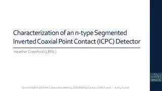
An LEC glass counter SiPM with pre-amplifier board 12mmx12mm Hamamatsu Light guide Mirror coated clear acrylic Diffuser 3mm white acrylic Mounting flange Martensitic stainless steel LG block 40mm x 40mm x 200mm ZF2 (SF5) wrapped with specular reflective film and opaque tape
Modular assembly of 16 (4x4) LG counters 10 cm 9.5 cm H beam: W100x100mm 20 cm ~17 cm
ADC & readout board LEC mechanics (top orientation*) Cooling water Cable channel * proposed side- and and bottom- orientations in the following slides Cable (Mini HDMI) Alignment/tightening screws rollers Bracket Standoff plates Front-end boards
LEC mechanics (bottom orientation) F/E boards bracket is longer than the top version in order to make room for the rollers: rollers Top Alignment/tightening screws Bottom Cooling water Cable channel
LEC mechanics (side orientation) roller Cable channel roller Asymmetrical bracket for horizontal support and alignment F/E boards Alignment/ tightening screws Cooling water roller
Rear access to LEC electronics H-beam H-beam ~7cm 10 cm 10 cm ~7 cm gaps between H beams allow access to cable connectors on the SiPM/preamplifier front-end boards
Installation strategy for HRD All four sides of a (central) HRD section are instrumented and cabled This favors a design with large-area sections to avoid coverage gaps This also means that the HRD cannot be supported or rest on any side. Proposed solution: Glue scintillating staves together into large Monolithic HRD sections Use thin steel cables to hang top/side HRD sections from overhead beams Install the bottom HRD section on a platform above the bottom LEC layer.
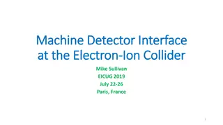
Supporting the HRD scintillators Top and side HRD suspended by steel cables from top H-beam Top HRD suspended by 2.5mm diam. steel cables from top H-beams. These cables must pass through the LG detector, requiring slightly wider gaps between some LG rows (e.g. ~6mm instead of 2.5mm) 0.2 x 5 x 5.5 0.3 x 3.74 x 4m Top cables pass through the HRD to support anchors below 0.3 x 4.4 x 4m 0.2 x 4.5 x 4 0.2 x 4.5 x 4 Bottom HRD can be supported by a platform of low-density material (carbon composite?). Platform supported from bottom H-beams through gaps in LG layer. Side HRDs suspended from top H-beams by 2.5mm cables. Each cable passes through the HRD from front to back 0.3 x 3.74 x 4m 0.2 x 5 x 5.5 0.2 x 5 x 5.5 Bottom HRD supported by a platform Steel suspension cables: 2mm: up to ~230 kg, 2.5mm: up to ~430kg, Platform supports
Passing cables through the HRD Steel cable 2 - 2.5 mm 5mm steel tube 5mm gaps between staves around hanging points Horizontal and vertical staves bonded together with glue or double-sided tape
Supporting the beam tube inside the experiment 0.2 x 5 x 5.5 0.3 x 4.4 x 4m 2.04 x 0.85 x 2m 2.04 x 0.85 x 2m Circular rib (steel) Maintains shape and provides attachment points 2.04 x 0.85 x 2m 2.04 x 0.85 x 2m 0.3 x 4.4 x 4m Beam tube (2cm Al) 0.2 x 5 x 5.5 Possible support point locations
NNBar support structure requirements Steel support structure Attachment points for horizontal LEC support H-beams Hanging points for top-and side HRD sections Resting point for bottom HRD section Horizontal & diagonal braces for stability/rigidity Concrete shielding 2m thick shielding blocks for radiation protection and cosmic shielding Cosmic veto detector installed on inner wall Working platforms and ladders Safe access to all areas of the detector
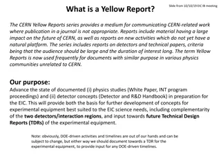
Top view 0.2 x 5.5 x 4 0.3 x 4.4 x 4m 1.87 x 0.85 x 2m 1.87 x 0.85 x 2m 0.3 x 3.74 x 4m 2.04 x 0.85 x 2m 2.04 x 0.85 x 2m 1.87 x 0.85 x 2m 1.87 x 0.85 x 2m 0.3 x 4.4 x 4m 0.2 x 5.5 x 4 End cap (LEC support) Cross section along center line Cross section around target 0.2 x 5 x 5.5 0.2 x 5.5 x 4 0.3 x 3.74 x 4m 0.3 x 4.4 x 4m 0.2 x 1.45 x 3.5m 0.2 x 1.45 x 3.5m 2.04 x 0.85 x 2m 2.04 x 0.85 x 2m 1.87 x 0.85 x 2m 2.04 x 0.85 x 2m 1.87 x 0.85 x 2m 0.3 x 4.4 x 4m 0.3 x 4.4 x 4m 0.2 x 4.5 x 4 0.2 x 4.5 x 4 0.2 x 1.45 x 3.2m 1.87 x 0.85 x 2m 1.87 x 0.85 x 2m 2.04 x 0.85 x 2m 2.04 x 0.85 x 2m 2.04 x 0.85 x 2m 0.2 x 1.45 x 3.5m 0.3 x 4.4 x 4m 0.3 x 3.74 x 4m 0.2 x 5.5 x 4 0.2 x 5 x 5.5 0.2 x 5 x 5.5 ~125 cm2 LEC support beams W100x100mm 9,5 cm h, 10 cm w Tweb: 9 mm Horizontal support beams W10x22 (W230x32.7) 26 cm h, 14.6 cm w Tweb: 6.1 mm Vertical supports RHS 300 x 200 mm (10mm thickness) Horizontal braces
Cross section around target Concrete shield 2m thick 0.2 x 5 x 5.5 0.3 x 3.74 x 4m 1.87 x 0.85 x 2m 2.04 x 0.85 x 2m 1.87 x 0.85 x 2m 0.3 x 4.4 x 4m 0.3 x 4.4 x 4m 0.2 x 4.5 x 4 0.2 x 4.5 x 4 1.87 x 0.85 x 2m 1.87 x 0.85 x 2m 2.04 x 0.85 x 2m 0.3 x 3.74 x 4m 0.2 x 5 x 5.5 0.2 x 5 x 5.5 LEC support beams W100x100mm 9,5 cm h, 10 cm w Tweb: 9 mm Horizontal support beams W10x22 (W230x32.7) 26 cm h, 14.6 cm w Tweb: 6.1 mm Vertical supports RHS 300 x 200 mm (10mm thickness) Working platforms, steps Cosmic veto layer Diagonal braces Platform supports for bottom HRD section (custom)
Cross section around endcap Concrete shield 2m thick 0.2 x 1.45 x 3.5m 0.2 x 1.45 x 3.5m 0.2 x 1.45 x 3.2m 0.2 x 1.45 x 3.5m LEC support beams W100x100mm 9,5 cm h, 10 cm w Tweb: 9 mm Horizontal support beams W10x22 (W230x32.7) 26 cm h, 14.6 cm w Tweb: 6.1 mm Vertical supports RHS 300 x 200 mm (10mm thickness) Working platforms, steps Cosmic veto layer Diagonal/ horizontal braces Platform supports for bottom HRD section (custom)
Side view Concrete shield 2m thick 0.2 x 5.5 x 4 0.3 x 4.4 x 4m 2.04 x 0.85 x 2m 2.04 x 0.85 x 2m 2.04 x 0.85 x 2m 2.04 x 0.85 x 2m 0.3 x 4.4 x 4m 0.2 x 5.5 x 4 LEC support beams W100x100mm 9,5 cm h, 10 cm w Tweb: 9 mm Horizontal support beams W10x22 (W230x32.7) 26 cm h, 14.6 cm w Tweb: 6.1 mm Vertical supports RHS 300 x 200 mm (10mm thickness) Working platforms, steps Cosmic veto layer Diagonal/ horizontal braces Platform supports for bottom HRD section (custom)
Summary Main features of the proposed design LEC arranged in modular sections (17cm x17cm) installed on horizontal H- beams HRD in large monolithic sections Top and sides suspended from thin steel cables Bottom secton supported by a platform Beam tube can be suspended within the detector volume if needed Cosmic veto mounted on insides of concrete enclosure. Still to be added to the design Support structure for the TPC chambers Si tracker cabling and services I did not cover the installation plan in this talk I believe it is possible to install the detector as described here But it will require careful planning and scheduling!


")

 LG counters")


")