Caterpillar Cat 980K Wheel Loader (Prefix NEP) Service Repair Manual Instant Download
Please open the website below to get the complete manualnn//

Download Presentation

Please find below an Image/Link to download the presentation.
The content on the website is provided AS IS for your information and personal use only. It may not be sold, licensed, or shared on other websites without obtaining consent from the author. Download presentation by click this link. If you encounter any issues during the download, it is possible that the publisher has removed the file from their server.
E N D
Presentation Transcript
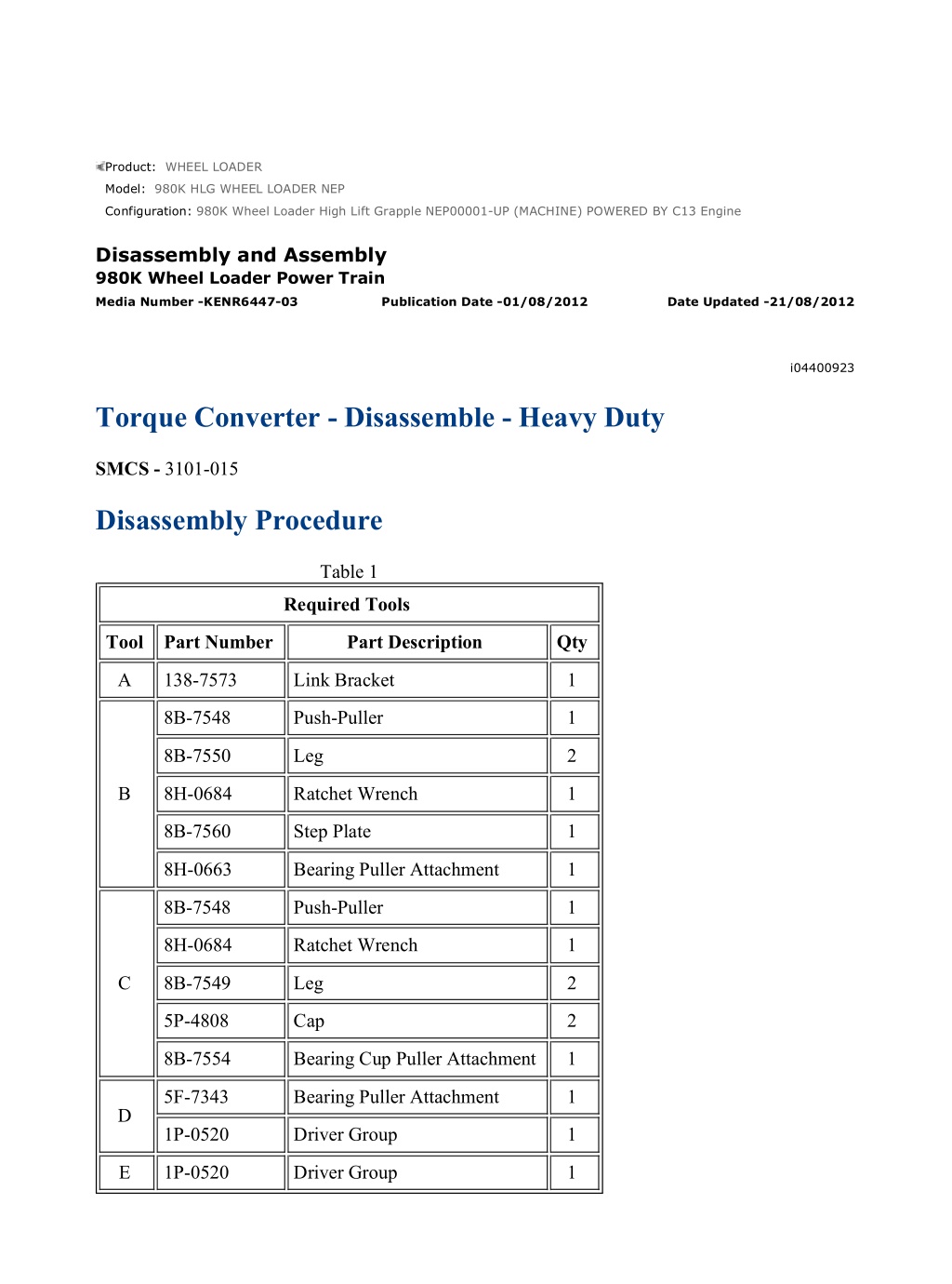
w 1/17(W) Product: WHEEL LOADER Model: 980K HLG WHEEL LOADER NEP Configuration: 980K Wheel Loader High Lift Grapple NEP00001-UP (MACHINE) POWERED BY C13 Engine Disassembly and Assembly 980K Wheel Loader Power Train Media Number -KENR6447-03 Publication Date -01/08/2012 Date Updated -21/08/2012 i04400923 Torque Converter - Disassemble - Heavy Duty SMCS - 3101-015 Disassembly Procedure Table 1 Required Tools Tool Part Number Part Description Qty A 138-7573 Link Bracket 1 8B-7548 Push-Puller 1 8B-7550 Leg 2 B 8H-0684 Ratchet Wrench 1 8B-7560 Step Plate 1 8H-0663 Bearing Puller Attachment 1 8B-7548 Push-Puller 1 8H-0684 Ratchet Wrench 1 C 8B-7549 Leg 2 5P-4808 Cap 2 8B-7554 Bearing Cup Puller Attachment 1 5F-7343 Bearing Puller Attachment 1 D 1P-0520 Driver Group 1 E 1P-0520 Driver Group 1 https://127.0.0.1/sisweb/sisweb/techdoc/techdoc_print_page.jsp?returnurl=/sisweb/sisw... 2022/2/13
w 2/17(W) Start By: a. Separate the torque converter from the transmission and from the output transfer gears. Refer to Disassembly and Assembly, "Torque Converter from Transmission, Output Transfer Gears - Separate" for the machine that is being serviced. 1. Place the torque converter housing assembly on wood blocks. Illustration 1 g00503225 2. Remove eight bolts (1) and the washers from torque converter housing assembly (2). Illustration 2 g00503286 3. Install Tooling (A) to torque converter housing assembly (2), as shown. Attach a hoist and suitable lifting chains to Tooling (A). 4. Use three 3/8" - 16 NC forcing screws (3) to loosen housing assembly (2) from the torque converter. 5. Use the hoist to remove housing assembly (2) from the torque converter. The weight of housing assembly (2) is 120 kg (265 lb). https://127.0.0.1/sisweb/sisweb/techdoc/techdoc_print_page.jsp?returnurl=/sisweb/sisw... 2022/2/13
w 3/17(W) Illustration 3 g00503287 6. Remove O-ring seal (4) from torque converter housing assembly (2). Illustration 4 g00503288 7. Remove thirteen bolts (5) and the washers from pump adapter (6) and torque converter housing assembly (2). Illustration 5 g00503289 8. Use three 3/8" - 16 NC forcing screws (7) to remove pump adapter (6) from torque converter housing assembly (2). https://127.0.0.1/sisweb/sisweb/techdoc/techdoc_print_page.jsp?returnurl=/sisweb/sisw... 2022/2/13
https://www.ebooklibonline.com Hello dear friend! Thank you very much for reading. Enter the link into your browser. The full manual is available for immediate download. https://www.ebooklibonline.com
w 4/17(W) Illustration 6 g00503291 9. Remove bearing cup (8), O-ring seal (10) and shims (9) from pump adapter (6). Illustration 7 g00503292 10. Remove pump drive gear (11) from torque converter housing assembly (2). Illustration 8 g00503294 11. Use Tooling (B) to remove bearing cones (12) from each side to pump drive gear (11). https://127.0.0.1/sisweb/sisweb/techdoc/techdoc_print_page.jsp?returnurl=/sisweb/sisw... 2022/2/13
w 5/17(W) Illustration 9 g00503296 12. Use Tooling (C) to remove bearing cup (13) from torque converter housing assembly (2). Illustration 10 g00503297 13. Remove bolt (14) and the washer from torque converter housing assembly (2). 14. Use 3/8" - 16 NC forcing screw (16) to push the shaft assembly out of torque converter housing assembly (2). 15. Remove idler gear (15) from torque converter housing assembly (2). Illustration 11 g00503298 https://127.0.0.1/sisweb/sisweb/techdoc/techdoc_print_page.jsp?returnurl=/sisweb/sisw... 2022/2/13
w 6/17(W) 16. Remove O-ring seal (17) from shaft assembly (18). Illustration 12 g00503299 17. Remove bearing cone (19), bearing cone spacer (20) and bearing cone (21) from idler gear (15). Illustration 13 g00503301 18. Use Tooling (C) to remove bearing cup (22) from idler gear (15). https://127.0.0.1/sisweb/sisweb/techdoc/techdoc_print_page.jsp?returnurl=/sisweb/sisw... 2022/2/13
w 7/17(W) Illustration 14 g00503302 19. Remove bearing cup spacer (23) from idler gear (15). Illustration 15 g00503308 20. Remove retaining ring (24) from idler gear (15). Illustration 16 g00503309 https://127.0.0.1/sisweb/sisweb/techdoc/techdoc_print_page.jsp?returnurl=/sisweb/sisw... 2022/2/13
w 8/17(W) 21. Use Tooling (C) to remove bearing cup (25) from idler gear (15). Illustration 17 g00503312 22. Remove two studs (26) from torque converter housing assembly (2). Illustration 18 g00503314 23. Remove retaining ring (27) and bearing carrier (28) from the carrier assembly. Illustration 19 g00503315 24. Remove O-ring seal (29) from bearing carrier (28). https://127.0.0.1/sisweb/sisweb/techdoc/techdoc_print_page.jsp?returnurl=/sisweb/sisw... 2022/2/13
w 9/17(W) 25. Remove seal ring (30) from ring carrier (31). Illustration 20 g00503316 26. Use Tooling (D) and a press to remove ring carrier (31) from bearing carrier (28). Illustration 21 g00503318 27. Remove retaining ring (32) from bearing carrier (28). Illustration 22 g00503319 28. Use Tooling (D) and a press to remove inner bearing (33) from bearing carrier (28). https://127.0.0.1/sisweb/sisweb/techdoc/techdoc_print_page.jsp?returnurl=/sisweb/sisw... 2022/2/13
w 10/17(W) Illustration 23 g00503321 29. Remove twelve bolts (34) and the washers from drive gear (35). 30. Remove drive gear (35) from the drive flange. Illustration 24 g00503322 31. Use Tooling (E) and a press to remove the outer bearing race from drive gear (35). Illustration 25 g00503344 32. Remove retaining ring (36) from drive gear (35). https://127.0.0.1/sisweb/sisweb/techdoc/techdoc_print_page.jsp?returnurl=/sisweb/sisw... 2022/2/13
w 11/17(W) Illustration 26 g00503345 33. Remove 36 bolts (37) from drive flange (38) and rotating housing (39). Illustration 27 g00503347 34. Use two bolts (37) as forcing screws to remove drive flange (38) from rotating housing (39). The weight of drive flange (38) is 23 kg (51 lb). Illustration 28 g00503348 35. Place the impeller hub on wood blocks. 36. Remove twelve bolts (40) from drive flange (38). https://127.0.0.1/sisweb/sisweb/techdoc/techdoc_print_page.jsp?returnurl=/sisweb/sisw... 2022/2/13
w 12/17(W) Illustration 29 g00503350 37. Remove drive flange (38) from the impeller hub and converter impeller (41). Illustration 30 g00503351 38. Remove converter impeller (41) from impeller hub (42). Illustration 31 g00503352 39. Remove two thrust bearing races (43) and the thrust bearing from the carrier assembly. https://127.0.0.1/sisweb/sisweb/techdoc/techdoc_print_page.jsp?returnurl=/sisweb/sisw... 2022/2/13
w 13/17(W) Illustration 32 g00503533 40. Remove carrier assembly (44) and the stator as a unit from rotating housing (39). Illustration 33 g00503534 41. Remove snap ring (45). Illustration 34 g00503535 42. Heat stator (46) and carrier assembly (44) as a unit to a minimum temperature of 121 C (250 F) for one hour. This will expand stator (46). 43. Remove stator (46) from carrier assembly (44). https://127.0.0.1/sisweb/sisweb/techdoc/techdoc_print_page.jsp?returnurl=/sisweb/sisw... 2022/2/13
w 14/17(W) Illustration 35 g00503536 44. Remove retainer ring (47) from stator (46). Illustration 36 g00503537 45. Remove sleeve bearing (48) from carrier assembly (44). Illustration 37 g00503538 46. Remove two thrust bearing races (49) and the thrust bearing from the hub. https://127.0.0.1/sisweb/sisweb/techdoc/techdoc_print_page.jsp?returnurl=/sisweb/sisw... 2022/2/13
w 15/17(W) Illustration 38 g00503539 47. Remove converter turbine (50) and turbine hub (51) as a unit from rotating housing (39). Illustration 39 g00503540 48. Remove twenty bolts (52) and the washers from converter turbine (50). 49. Remove converter turbine (50) from turbine hub (51). Illustration 40 g00503541 50. Remove retaining ring (53) from turbine hub (51). https://127.0.0.1/sisweb/sisweb/techdoc/techdoc_print_page.jsp?returnurl=/sisweb/sisw... 2022/2/13
w 16/17(W) Illustration 41 g00503542 51. Remove two thrust bearing races (54) and thrust bearing (55) from the cover assembly. Illustration 42 g00503564 52. Remove eight bolts (56) and the washers from cover assembly (57). 53. Remove cover assembly (57) from rotating housing (39). 54. Remove ring seal (58) from rotating housing (39). Illustration 43 g00503567 55. Remove sleeve bearing (59) from cover assembly (57). https://127.0.0.1/sisweb/sisweb/techdoc/techdoc_print_page.jsp?returnurl=/sisweb/sisw... 2022/2/13
w 1/17(W) Product: WHEEL LOADER Model: 980K HLG WHEEL LOADER NEP Configuration: 980K Wheel Loader High Lift Grapple NEP00001-UP (MACHINE) POWERED BY C13 Engine Disassembly and Assembly 980K Wheel Loader Power Train Media Number -KENR6447-03 Publication Date -01/08/2012 Date Updated -21/08/2012 i06838048 Torque Converter - Disassemble - Lock Up Clutch With Freewheel Stator SMCS - 3101-015 Disassembly Procedure Table 1 Required Tools Tool Part Number Part Description Qty A 439-3938 Link Bracket 3 8B-7548 Push-Puller 1 8B-7550 Leg 2 B 8H-0684 Ratchet Wrench 1 8B-7560 Step Plate 1 8H-0663 Bearing Puller Attachment 1 8B-7548 Push-Puller 1 8H-0684 Ratchet Wrench 1 C 8B-7549 Leg 2 5P-4808 Cap 2 8B-7554 Bearing Cup Puller Attachment 1 5F-7343 Bearing Puller Attachment 1 D 1P-0520 Driver Group 1 E 1P-0510 Driver Group 1 https://127.0.0.1/sisweb/sisweb/techdoc/techdoc_print_page.jsp?returnurl=/sisweb/sisw... 2022/2/13
w 2/17(W) F 6L-7283 Forcing Bolt 3/8 - 16 by 3 in 7 G 417-1324 Adjust Stand 1 Start By: a. Separate the torque converter from the transmission and from the output transfer gears. Illustration 1 g02712129 1. Use Tooling (A) and a suitable lifting device to position the torque converter onto Tooling (G) and suitable blocking. The weight of the torque converter is approximately 260 kg (573 lb). Support the torque converter, as shown. 2. Remove bolts (1). Illustration 2 g02730506 3. Remove relief valve assembly (2A). https://127.0.0.1/sisweb/sisweb/techdoc/techdoc_print_page.jsp?returnurl=/sisweb/sisw... 2022/2/13
w 3/17(W) Illustration 3 g02711758 4. Use Tooling (F) to loosen housing assembly (2) from the torque converter. 5. Use the suitable lifting device and Tooling (A) to remove torque converter housing assembly (2). The weight of torque converter housing assembly (2) is approximately 144 kg (317 lb). Illustration 4 g00871317 6. Remove O-ring seal (3) from torque converter housing assembly (2). Illustration 5 g00871318 https://127.0.0.1/sisweb/sisweb/techdoc/techdoc_print_page.jsp?returnurl=/sisweb/sisw... 2022/2/13
w 4/17(W) 7. Remove bolts (4) from pump adapter (5) and torque converter housing assembly (2). Illustration 6 g00871264 8. Use Tooling (F) to remove pump adapter (5) from torque converter housing assembly (2). Illustration 7 g00871319 9. Use Tooling (B) to remove bearing cup (6). Remove bearing cup (6), O-ring seal (8), and shims (7) from pump adapter (5). See illustration 14 for Tooling (C). Illustration 8 g00871326 10. Remove pump drive gear (9) from torque converter housing assembly (2). https://127.0.0.1/sisweb/sisweb/techdoc/techdoc_print_page.jsp?returnurl=/sisweb/sisw... 2022/2/13
w 5/17(W) Illustration 9 g00871451 11. Use Tooling (C) to remove bearing cones (10) from each side of pump drive gear (9). Remove bearing cones (10). Illustration 10 g00871333 12. Use Tooling (C) to remove bearing cup (11) from torque converter housing assembly (2). See illustration 14 for Tooling (C). Illustration 11 g01112900 13. Remove bolt (12) and the washer from torque converter housing assembly (2). https://127.0.0.1/sisweb/sisweb/techdoc/techdoc_print_page.jsp?returnurl=/sisweb/sisw... 2022/2/13
w 6/17(W) 14. Use Tooling (F) to push shaft assembly (14) out of torque converter housing assembly (2). 15. Remove idler gear (13) from torque converter housing assembly (2). Illustration 12 g01112903 16. Remove O-ring seal (15) from shaft assembly (14). Illustration 13 g00871365 17. Remove bearing cone (16), bearing cone spacer (17), and bearing cone (18) from idler gear (13). https://127.0.0.1/sisweb/sisweb/techdoc/techdoc_print_page.jsp?returnurl=/sisweb/sisw... 2022/2/13
w 7/17(W) Illustration 14 g00871366 18. Use Tooling (C) to remove bearing cup (19) from idler gear (13). Remove bearing cup (19). Illustration 15 g00871367 19. Remove bearing cup spacer (20) from idler gear (13). Illustration 16 g00871368 https://127.0.0.1/sisweb/sisweb/techdoc/techdoc_print_page.jsp?returnurl=/sisweb/sisw... 2022/2/13
w 8/17(W) 20. Remove retaining ring (21) from idler gear (13). Illustration 17 g00871369 21. Use Tooling (C) to remove bearing cup (22) from idler gear (13). Remove bearing cup (22). Illustration 18 g00871370 22. Remove studs (23) from torque converter housing assembly (2). https://127.0.0.1/sisweb/sisweb/techdoc/techdoc_print_page.jsp?returnurl=/sisweb/sisw... 2022/2/13
w 9/17(W) Illustration 19 g02729366 23. Remove bolts (24) and gear (25). Illustration 20 g02735357 24. Use the driver group from Tooling (D) and a suitable press to remove race (25A) from gear (25). Illustration 21 g02730012 25. Use a suitable lifting device to reposition the torque converter, as shown. The weight of the torque converter is approximately 122 kg (269 lb). Remove bolts (26). https://127.0.0.1/sisweb/sisweb/techdoc/techdoc_print_page.jsp?returnurl=/sisweb/sisw... 2022/2/13
w 10/17(W) Illustration 22 g02730687 26. Use Tooling (F) to separate housing (27) from the torque converter. Illustration 23 g02730689 27. Use two people to remove housing (27). The weight of housing (27) is approximately 26 kg (57 lb). Remove housing (27), piston (28), and plate (30). Remove seals (29) from piston (28). Illustration 24 g02731059 28. Remove bushing (31) from housing (27). https://127.0.0.1/sisweb/sisweb/techdoc/techdoc_print_page.jsp?returnurl=/sisweb/sisw... 2022/2/13
w 11/17(W) Illustration 25 g02731623 29. Remove plate (32), disk (33), races (34), and bearing (35). Note: Note the orientation of the bearing and races for assembly purposes. Illustration 26 g02731644 30. Remove bolts (36), coupling assembly (37), and plate (38). https://127.0.0.1/sisweb/sisweb/techdoc/techdoc_print_page.jsp?returnurl=/sisweb/sisw... 2022/2/13
Suggest: If the above button click is invalid. Please download this document first, and then click the above link to download the complete manual. Thank you so much for reading
w 12/17(W) Illustration 27 g02731651 31. Use suitable blocking to support the bottom of shaft assembly (39). Remove retaining ring (40) and plate (41). Shaft assembly (39) can be lowered to the work bench. Illustration 28 g02731711 Illustration 29 g02732048 https://127.0.0.1/sisweb/sisweb/techdoc/techdoc_print_page.jsp?returnurl=/sisweb/sisw... 2022/2/13
https://www.ebooklibonline.com Hello dear friend! Thank you very much for reading. Enter the link into your browser. The full manual is available for immediate download. https://www.ebooklibonline.com