Caterpillar Cat 375 and 375L TRACK-TYPE EXCAVATOR (Prefix 6RL) Service Repair Manual Instant Download 9
Please open the website below to get the complete manualnn//

Download Presentation

Please find below an Image/Link to download the presentation.
The content on the website is provided AS IS for your information and personal use only. It may not be sold, licensed, or shared on other websites without obtaining consent from the author. Download presentation by click this link. If you encounter any issues during the download, it is possible that the publisher has removed the file from their server.
E N D
Presentation Transcript
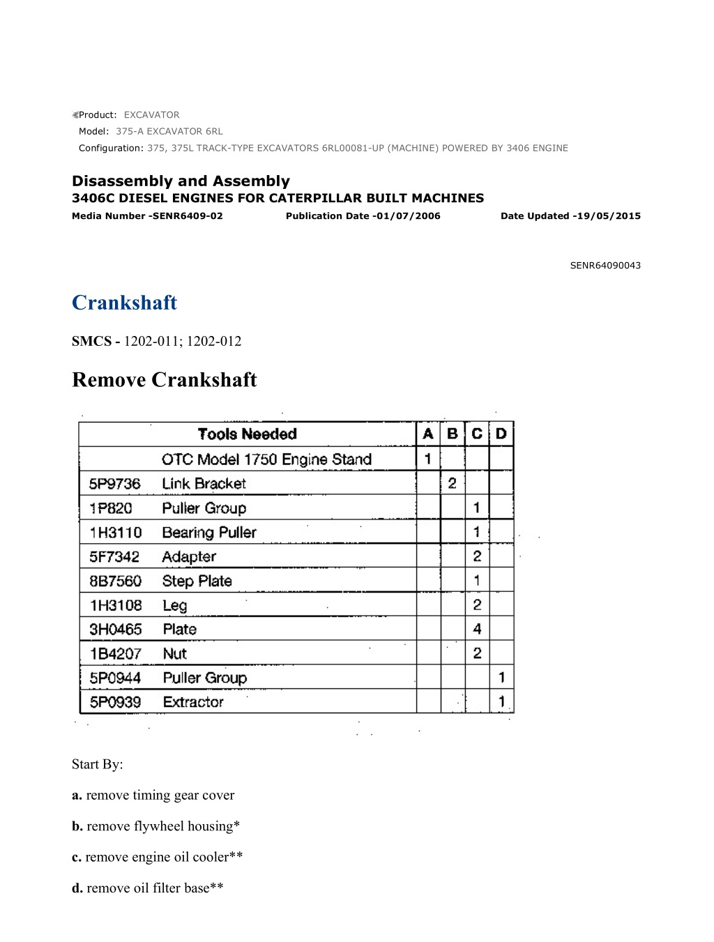
375, 375L TRACK-TYPE EXCAVATORS 6RL00081-UP (MACHINE) POWERED ... 1/8 Product: EXCAVATOR Model: 375-A EXCAVATOR 6RL Configuration: 375, 375L TRACK-TYPE EXCAVATORS 6RL00081-UP (MACHINE) POWERED BY 3406 ENGINE Disassembly and Assembly 3406C DIESEL ENGINES FOR CATERPILLAR BUILT MACHINES Media Number -SENR6409-02 Publication Date -01/07/2006 Date Updated -19/05/2015 SENR64090043 Crankshaft SMCS - 1202-011; 1202-012 Remove Crankshaft Start By: a. remove timing gear cover b. remove flywheel housing* c. remove engine oil cooler** d. remove oil filter base** https://127.0.0.1/sisweb/sisweb/techdoc/techdoc_print_page.jsp?returnurl=/sis... 2020/12/25
375, 375L TRACK-TYPE EXCAVATORS 6RL00081-UP (MACHINE) POWERED ... 2/8 *Put the engine in time before the flywheel housing is removed. See the topic, "Finding Top Center Compression Position For No. 1 Piston" in Testing & Adjusting Manual SENR6471. **These operations must be done to install Tool (A) on the engine. Typical Example 1. Fasten the engine on Tool (A). The weight of the engine is 1362 kg (3000 lb). 2. Remove the bolts and nuts that hold air cleaner group (1), pipe assembly (3), bracket assembly (4) and lifting plate (5) as a unit to the engine. Fasten a hoist to the unit and remove it from the engine. The weight of the unit is approximately 39 kg (85 lb). 3. Remove tube assembly (2) from the engine. Typical Example 4. Install the two bolts to hold the primary fuel filter bracket (6) in place while the engine is turned with Tool (A). 5. Turn the engine to the position shown with Tool (A). Remove rod bearing caps (8) from the ends of the connecting rods. Push the connecting rods away from the crankshaft. 6. Remove the bolts and remove main bearing caps (7) from the crankshaft. https://127.0.0.1/sisweb/sisweb/techdoc/techdoc_print_page.jsp?returnurl=/sis... 2020/12/25
375, 375L TRACK-TYPE EXCAVATORS 6RL00081-UP (MACHINE) POWERED ... 3/8 7. Remove thrust plates (9) from the center main bearing journal. 8. Fasten a hoist to crankshaft (10) with tooling (B). Remove crankshaft (10) from the engine block. The weight of the crankshaft is 159 kg (350 lb). 9. Use Tool (C) to remove outer gear (2) from the end of the crankshaft. 10. Use a hammer and chisel to remove the spacer from the crankshaft. 11. Use Tool (D) to remove the gear alignment dowel from the crankshaft. 12. Use Tool (C) to remove inner gear (11) from the end of the crankshaft. https://127.0.0.1/sisweb/sisweb/techdoc/techdoc_print_page.jsp?returnurl=/sis... 2020/12/25
https://www.ebooklibonline.com Hello dear friend! Thank you very much for reading. Enter the link into your browser. The full manual is available for immediate download. https://www.ebooklibonline.com
375, 375L TRACK-TYPE EXCAVATORS 6RL00081-UP (MACHINE) POWERED ... 4/8 NOTE: If new main bearings are not to be installed, put identification on the old main bearings as to their location in the cylinder block and to which main bearings caps they belong. 13. Remove main bearings (13) from the cylinder block and the main bearing caps. Install Crankshaft 1. If the dowel was removed from the flywheel end of the crankshaft, install it in the crankshaft to a maximum dimension of 6.4 mm (.25 in). 2. Heat the crankshaft gears to a maximum temperature of 205 C (400 F). 3. The centerline of inner gear key must be in alignment with the centerline of the dowel hole within 0.51 mm (.020 in). Install crankshaft inner gear (14) on the crankshaft. 4. Install the spacer on the crankshaft. 5. Install the dowel in the crankshaft. The dowel must be extended no more than 4.1 0.5 mm (.16 .02 in) from the surface of the crankshaft. NOTE: The dowel in the crankshaft must be in alignment with the notch in crankshaft gear (15). 6. Make sure the "V" mark on the crankshaft gear is toward the outside, and install crankshaft gear (15). https://127.0.0.1/sisweb/sisweb/techdoc/techdoc_print_page.jsp?returnurl=/sis... 2020/12/25
375, 375L TRACK-TYPE EXCAVATORS 6RL00081-UP (MACHINE) POWERED ... 5/8 7. Thoroughly clean the cylinder block and main bearing caps. NOTICE Make sure the upper and lower halves of the main bearings are installed so the bearing tabs fit into the notch in the cylinder block and main bearing caps. NOTE: Install the main bearings dry when the clearance checks are made. Put clean engine oil on the main bearings for final assembly. 8. Install the upper half of main bearings (13) (bearings with oil holes) in the cylinder block. 9. Fasten a hoist to crankshaft (10) with tooling (B) and put it in position on the cylinder block. Make sure the "V" marks on the crankshaft and the idler gear are in alignment and the "K" marks on the camshaft gear can be seen at the outer edges of the idler gear. The timing gears are in correct position. 10. Install thrust plates (9) on both sides of the center main bearing journal. Make sure the plates are installed with side marked "BLOCK SIDE" toward the cylinder block. 11. Install the lower half of main bearings (13) in main bearing caps (7). https://127.0.0.1/sisweb/sisweb/techdoc/techdoc_print_page.jsp?returnurl=/sis... 2020/12/25
375, 375L TRACK-TYPE EXCAVATORS 6RL00081-UP (MACHINE) POWERED ... 6/8 NOTE: When the bearing clearance is checked and the engine is vertical position, such as in the vehicle, the crankshaft will have to be lifted up and held against the upper halves of the main bearings to get a correct measurement with the Plastigage. The Plastigage will not hold the weight of the crankshaft and give a correct indication. If the engine is in a horizontal position, it is not necessary to hold the crankshaft up. Do not turn the crankshaft when the Plastigage is in position to check clearances. 12. Put a piece of Plastigage on the surface of the lower main bearing half. 13. Install main bearing caps (7) with the arrow on the bottom surface of the cap toward the front of the cylinder block. Also, the stamped number on the cap must be the same as the cast number on the left side of the cylinder block. NOTICE Do not use an impact wrench to tighten the bolts the additional 120 5 degrees of a turn more. 14. Put 2P2506 Thread Lubricant on the threads of the main bearing cap bolts. Install the bolts and tighten them as follows: a. Tighten the tab end bolt to a torque of 258 14 N m (190 10 lb ft). b. Tighten the opposite end bolt to a torque of 258 14 N m (190 10 lb ft). c. Turn the opposite end bolt an additional 120 5 degrees. d. Turn the tab end bolt an additional 120 5 degrees. 15. Remove the main bearing caps and measure the Plastigage. The main bearing clearance must be 0.091 - 0.185 mm (.0036 - .0073 in) with new bearings. Maximum clearance with used bearings is 0.25 mm (.010 in). 16. Install the main bearing caps again and tighten the bolts as in Step 13. https://127.0.0.1/sisweb/sisweb/techdoc/techdoc_print_page.jsp?returnurl=/sis... 2020/12/25
375, 375L TRACK-TYPE EXCAVATORS 6RL00081-UP (MACHINE) POWERED ... 7/8 17. Put the connecting rods in position on the crankshaft. Install rod bearing caps (8) with the bolts and nuts to hold them. See the topic, "Remove & Install Connecting Rod Bearings", for the correct bolt tightening procedure and bearing clearance check procedure. 18. Check the crankshaft end play with tooling (E). The end play is controlled by the thrust plates on the center main bearing. End play with new plates is 0.15 - 0.51 mm (.006 - .020 in). The maximum permissible end play with used bearings is 0.89 mm (.035 in). 19. Use Tool (A) to turn the engine back to its vertical position as shown. 20. Install tube assembly (2) on the engine. 21. Fasten a hoist to and install air cleaner group (1), pipe assembly (3), bracket assembly (4) and lifting plate (5) as a unit on the engine. End By: a. install oil filter base b. install engine oil cooler c. install flywheel housing d. install timing gear cover https://127.0.0.1/sisweb/sisweb/techdoc/techdoc_print_page.jsp?returnurl=/sis... 2020/12/25
375, 375L TRACK-TYPE EXCAVATORS 6RL00081-UP (MACHINE) POWERED ... 1/7 Product: EXCAVATOR Model: 375-A EXCAVATOR 6RL Configuration: 375, 375L TRACK-TYPE EXCAVATORS 6RL00081-UP (MACHINE) POWERED BY 3406 ENGINE Disassembly and Assembly 375 EXCAVATOR MACHINE SYSTEMS Media Number -SENR6027-02 Publication Date -01/06/2004 Date Updated -10/08/2009 SENR60270001 Conventional Duo-Cone Seals SMCS - 7561-012; 7561-016 Assembly And Installation Of Conventional Duo-Cone Seals This instruction gives the procedure for installing Conventional Duo-Cone Seals. It is most important that correct assembly and installation procedures are followed when Duo- Cone Seals are used. Many of the Duo-Cone Seal failures are the direct result of one or more mistakes made during assembly or installation of the seal components. (1) Seal (2) Rubber Toric Ring (3) Housing Retaining Lip (4) Housing Ramp (5) Seal Ring Housing https://127.0.0.1/sisweb/sisweb/techdoc/techdoc_print_page.jsp?returnurl=/sis... 2020/12/25
375, 375L TRACK-TYPE EXCAVATORS 6RL00081-UP (MACHINE) POWERED ... 2/7 (6) Seal Ring Face (7) Seal Ring Ramp (8) Seal Ring Retaining Lip (9) Installation Tool. 1. Remove any oil film, dust or other foreign matter from toric rubber rings (2) and from ramps (4) and (7) and lips (3) and (8) of both seal rings (1) and housings (5). Use isopropyl alcohol and a suitable cloth for wiping. NOTICE Never permit oil to get on the toric rings or ramps before both seal rings are put together in their final assembled position (Step 10). https://127.0.0.1/sisweb/sisweb/techdoc/techdoc_print_page.jsp?returnurl=/sis... 2020/12/25
375, 375L TRACK-TYPE EXCAVATORS 6RL00081-UP (MACHINE) POWERED ... 3/7 2. Put toric ring (2) on seal ring (1), at the bottom of seal ring ramp (7) and against retaining lip (8). NOTICE Make sure that toric ring (2) is straight on seal ring (1) and is not twisted. Be careful when you work on the rubber toric ring. Nicks, cuts and scratches can cause leaks. 3. Put installation tool (9) onto seal ring (1) with toric ring (2). Lower the rings into a container with isopropyl alcohol until all surfaces of toric ring (2) are wet. NOTICE https://127.0.0.1/sisweb/sisweb/techdoc/techdoc_print_page.jsp?returnurl=/sis... 2020/12/25
375, 375L TRACK-TYPE EXCAVATORS 6RL00081-UP (MACHINE) POWERED ... 4/7 Do not use Stanisol or any other liquid that leaves an oil film or does not evaporate quickly. 4. With all surfaces of toric ring (2) wet, use installation tool (9) to position seal ring (1) and toric ring (2) squarely against housing (5) as shown. Use sudden and even pressure to pop (push) toric ring (2) under retaining lip (3) of housing (5). 5. Check assembled height (A) in at least four places, 90 apart. The difference in height around the ring must not be more than 1 mm (.04"). https://127.0.0.1/sisweb/sisweb/techdoc/techdoc_print_page.jsp?returnurl=/sis... 2020/12/25
375, 375L TRACK-TYPE EXCAVATORS 6RL00081-UP (MACHINE) POWERED ... 5/7 6. If small adjustments are necessary, do not push directly on seal ring (1); use installation tool (9). 7. Toric ring (2) can twist if it is not wet all around during installation or if there are burrs or fins on retaining lip (3) of housing (5). NOTICE Misalignment, twists and bulges of the toric ring will cause Duo-Cone Seal failures. If correct installation is not obvious, remove seal from housing and repeat steps 3 thru 6. IMPORTANT: Toric rings (2) must never slip on the ramps of either seal rings (1) or seal ring housings (5). To prevent slippage, wait a minimum of two minutes to let the isopropyl alcohol evaporate before further assembly. Once correctly in place, the toric ring must roll on the ramps only. https://127.0.0.1/sisweb/sisweb/techdoc/techdoc_print_page.jsp?returnurl=/sis... 2020/12/25
375, 375L TRACK-TYPE EXCAVATORS 6RL00081-UP (MACHINE) POWERED ... 6/7 8. Wipe seal faces (6) of seal rings (1) clean. Use a lint free cloth or paper towel. No particles of any kind are permissible on the sealing surfaces. Even a small piece from a paper towel can hold the seal faces apart and cause leakage. 9. Put a thin film of clean oil on the seal faces. Use an applicator, a disposable tissue or a clean finger to distribute the oil evenly. Be careful not to get any oil on the rubber toric rings. 10. Make sure both housings (5) are in correct alignment and are concentric. Move the parts slowly and carefully toward each other. NOTICE Do not slam seals together. High impact can scratch or break the seal components. https://127.0.0.1/sisweb/sisweb/techdoc/techdoc_print_page.jsp?returnurl=/sis... 2020/12/25
375, 375L TRACK-TYPE EXCAVATORS 6RL00081-UP (MACHINE) POWERED ... 7/7 11. Once in place, fasten all parts tightly. https://127.0.0.1/sisweb/sisweb/techdoc/techdoc_print_page.jsp?returnurl=/sis... 2020/12/25
375, 375L TRACK-TYPE EXCAVATORS 6RL00081-UP (MACHINE) POWERED ... 1/7 Product: EXCAVATOR Model: 375-A EXCAVATOR 6RL Configuration: 375, 375L TRACK-TYPE EXCAVATORS 6RL00081-UP (MACHINE) POWERED BY 3406 ENGINE Disassembly and Assembly 375 EXCAVATOR MACHINE SYSTEMS Media Number -SENR6027-02 Publication Date -01/06/2004 Date Updated -10/08/2009 SENR60270002 Bucket SMCS - 6101-010 Remove & Install Bucket https://127.0.0.1/sisweb/sisweb/techdoc/techdoc_print_page.jsp?returnurl=/sis... 2020/12/25
375, 375L TRACK-TYPE EXCAVATORS 6RL00081-UP (MACHINE) POWERED ... 2/7 Typical Example NOTICE To facilitate removal of the bucket pins without causing damage to the pins, bushings and/or O-ring seals, put the bucket flat on the floor and the stick in a vertical position as shown. https://127.0.0.1/sisweb/sisweb/techdoc/techdoc_print_page.jsp?returnurl=/sis... 2020/12/25
375, 375L TRACK-TYPE EXCAVATORS 6RL00081-UP (MACHINE) POWERED ... 3/7 1. Start the machine, and position the bucket, stick and rod links as shown. 2. Remove retaining bolt (1) and two nuts (2) from bucket pin (3). 3. Make sure the threaded puller hole in the bucket pin is clean prior to installation of Tooling (A). Fasten Tooling (A) to bucket pin (3) as shown. Fasten a lifting strap and a hoist to Tooling (A) to support it as shown. 4. Slide O-ring seal (5) off of the joints between the bucket and link assembly (4) and onto the flanges on the bucket. When bucket pin (3) is removed, link assembly (4) will swing forward and out of the bucket. To prevent possible personal injury, do not stand in front of link assembly (4) when bucket pin (3) is being removed. 5. Using Tooling (A), remove bucket pin (3) far enough to free link assembly (4) from the bucket. Do not remove bucket pin (3) completely from the bucket. Link assembly (4) will swing forward when the bucket pin is removed. https://127.0.0.1/sisweb/sisweb/techdoc/techdoc_print_page.jsp?returnurl=/sis... 2020/12/25
375, 375L TRACK-TYPE EXCAVATORS 6RL00081-UP (MACHINE) POWERED ... 4/7 6. Remove Tooling (A) from bucket pin (3). Remove bucket pin (3). The weight of the bucket pin is 77 kg (170 lb). Remove O-ring seal (5) from the flanges on the bucket. 7. Slide O-ring seal (7) off of the joints between the stick and bucket and onto the flanges on the bucket. Remove six bolts (6) and the washers that hold plate (8) in position over the end of bucket pin (12). Remove the plate. Remove shims (9) that are located under plate (8). 8. Remove retaining bolt (10) and two nuts (11) from bucket pin (12). 9. Make sure the threaded puller hole in the bucket pin is clean prior to installation of Tooling (B). Fasten Tooling (B) to bucket pin (12) as shown. Fasten a lifting strap and a hoist to Tooling (B) to support it. 10. Using Tooling (B), remove bucket pin (12) far enough until the stick is free of the bucket. Do not remove bucket pin (12) completely out of the bucket. 11. Remove Tooling (B) from bucket pin (12). Remove bucket pin (12). The weight of the bucket pin is 109 kg (240 lb). https://127.0.0.1/sisweb/sisweb/techdoc/techdoc_print_page.jsp?returnurl=/sis... 2020/12/25
375, 375L TRACK-TYPE EXCAVATORS 6RL00081-UP (MACHINE) POWERED ... 5/7 12. Start the machine, and raise the stick out of the bucket. The weight of the bucket can range from approximately 1996 to 3402 kg (4400 to 7500 lb). 13. Remove flange (13) from the bucket. 14. Remove O-ring seals (7) from the flanges on the bucket. NOTE: The following steps are for the installation of the bucket. NOTICE Make sure the stick pin bore, bucket pin bore, bucket pins, flange and O-ring seals are thoroughly clean prior to installation of the bucket. 15. Check the condition of O-ring seals (5) and (7). If the seals are worn or damaged, use new parts for replacement. 16. Put a thin coat of 5P-0960 Multipurpose Grease on the outside machined diameter and the inside bore of flange (13). Install flange (13) in the bucket as shown. 17. Temporarily install an O-ring seal (7) on each flange of the bucket at the bucket-to-stick pin bore. Start the machine, and lower the stick into the bucket until the pin bores are in alignment with each other. https://127.0.0.1/sisweb/sisweb/techdoc/techdoc_print_page.jsp?returnurl=/sis... 2020/12/25
375, 375L TRACK-TYPE EXCAVATORS 6RL00081-UP (MACHINE) POWERED ... 6/7 18. Make sure the threaded puller hole in the end of bucket pin (12) is clean. Put a thin coat of 5P- 0960 Multipurpose Grease on bucket pin (12). Install Tool (C) in the end of the bucket pin. Install bucket pin (12) with a hammer. Remove Tool (C) from the bucket pin. Put the retaining bolt hole in bucket pin (12) in alignment with the retaining bolt hole in the bucket. Temporarily install retaining bolt (10) and two nuts (11). 19. Align the locating hole in plate (8) with the locating pin in flange (13). Install plate (8), without shims (9), on flange (13). Install six bolts (6) and the washers. Tighten six bolts (6) evenly. 20. Move the bucket to one side until it makes contact with the stick. Measure the clearance between the bucket and stick at flange (13). Record this dimension. Add shims (9) between plate (8) and flange (13) until the clearance [dimension (X)] between the stick and bucket is 0.5 to 1.0 mm (.02 to .04 in). 21. Slide O-ring seals (7) over the joints between the bucket and stick. 22. Temporarily install an O-ring seal (5) on each flange of the bucket at the bucket-to-link assembly pin bore. https://127.0.0.1/sisweb/sisweb/techdoc/techdoc_print_page.jsp?returnurl=/sis... 2020/12/25
375, 375L TRACK-TYPE EXCAVATORS 6RL00081-UP (MACHINE) POWERED ... 7/7 23. Make sure the threaded puller hole in the end of bucket pin (3) is clean. Put a thin coat of 5P- 0960 Multipurpose Grease on bucket pin (3). Install Tool (D) in the end of bucket pin (3). Push the link assembly in position in the bucket. Install bucket pin (3) with a hammer. Remove Tool (D) from the bucket pin. Put the retaining bolt hole in bucket pin (3) in alignment with the retaining bolt hole in the bucket. Temporarily install retaining bolt (1) and two nuts (2). 24. Slide O-ring seals (5) over the joints between the bucket and link assembly. 25. Tighten retaining nuts (2) and (11) as shown in the illustration. Tighten the outside nut until it is even or 0.5 mm (.02 in) above the end of the retaining bolt. Tighten the inside nut against the outside nut. 26. Lubricate the bucket pins. See the Operation & Maintenance Manual for the correct procedure. https://127.0.0.1/sisweb/sisweb/techdoc/techdoc_print_page.jsp?returnurl=/sis... 2020/12/25
375, 375L TRACK-TYPE EXCAVATORS 6RL00081-UP (MACHINE) POWERED ... 1/8 Product: EXCAVATOR Model: 375-A EXCAVATOR 6RL Configuration: 375, 375L TRACK-TYPE EXCAVATORS 6RL00081-UP (MACHINE) POWERED BY 3406 ENGINE Disassembly and Assembly 375 EXCAVATOR MACHINE SYSTEMS Media Number -SENR6027-02 Publication Date -01/06/2004 Date Updated -10/08/2009 SENR60270003 Bucket Linkage SMCS - 6513-010 Remove & Install Bucket Linkage https://127.0.0.1/sisweb/sisweb/techdoc/techdoc_print_page.jsp?returnurl=/sis... 2020/12/25
375, 375L TRACK-TYPE EXCAVATORS 6RL00081-UP (MACHINE) POWERED ... 2/8 1. Start the machine, and position the bucket, stick and rod links as shown. https://127.0.0.1/sisweb/sisweb/techdoc/techdoc_print_page.jsp?returnurl=/sis... 2020/12/25
375, 375L TRACK-TYPE EXCAVATORS 6RL00081-UP (MACHINE) POWERED ... 3/8 2. Remove retaining bolt (1) and two nuts (2) from bucket pin (3). 3. Make sure the threaded puller hole in the bucket pin is clean prior to installation of Tooling (A). Fasten Tooling (A) to bucket pin (3) as shown. Fasten a lifting strap and a hoist to Tooling (A) to support it as shown. 4. Slide O-ring seals (5) off of the joints between the bucket and link assembly (4) and onto the flanges on the bucket. When bucket pin (3) is removed, link assembly (4) will swing forward and out of the bucket. To prevent possible personal injury, do not stand in front of link assembly (4) when bucket pin (3) is being removed. 5. Using Tooling (A), remove bucket pin (3) far enough to free link assembly (4) from the bucket. Do not remove bucket pin (3) completely from the bucket. Link assembly (4) will swing forward when the bucket pin is removed. 6. Remove Tooling (A) from bucket pin (3). Remove bucket pin (3). The weight of the bucket pin is 77kg (170 lb). Remove O-ring seals (5) from the flanges on the bucket. https://127.0.0.1/sisweb/sisweb/techdoc/techdoc_print_page.jsp?returnurl=/sis... 2020/12/25
375, 375L TRACK-TYPE EXCAVATORS 6RL00081-UP (MACHINE) POWERED ... 4/8 7. Fasten a hoist to link assembly (4) as shown, and raise it until it is in a horizontal position. 8. Remove two nuts (6) and retaining bolt (7) from pin (8). Remove pin (8) from the link assemblies and the rod end of the bucket cylinder. Remove link assembly (4). The weight of pin (8) is approximately 109 kg (240 lb). The weight of the link assembly can range from approximately 318 to 408 kg (700 to 900 lb). 9. Fasten a hoist to left hand link assembly (9) as shown. Remove two nuts (10) and retaining bolt (11) from pin (12). Using a hammer and punch, drive pin (12) into the stick until the left hand link assembly is free. Remove the left hand link assembly. The weight of the left hand link assembly is approximately 91 kg (200 lb). Refasten the hoist to the right hand link assembly. Remove pin (12) from the stick and right hand link assembly. Remove the right hand link assembly. The weight of the right hand link assembly is approximately 91 kg (200 lb). The weight of pin (12) is 77 kg (170 lb). 10. Remove six lip-type seals (13) from link assembly (4). https://127.0.0.1/sisweb/sisweb/techdoc/techdoc_print_page.jsp?returnurl=/sis... 2020/12/25
375, 375L TRACK-TYPE EXCAVATORS 6RL00081-UP (MACHINE) POWERED ... 5/8 11. Remove two bearings (14) from the open end of the link assembly with Tooling (B). Fasten tooling (B) to the link assembly as shown. Fasten a hoist to Tooling (B) to support it; then remove the bearing. Remove the bearing on the other side of the link assembly the same way. 12. Remove the two bearings from the closed end of the link assembly with a chisel or by cutting. 13. Remove two lip-type seals (15) from the stick at the stick-to-bucket linkage pin joint. Typical Example 14. Remove the two bearings from the stick at the stick-to-bucket linkage pin joint with Tooling (C). Fasten Tooling (C) to the bearing as shown. Fasten a hoist to Tooling (C) to support it; then remove the bearing. Remove the bearing on the other side of the stick the same way. NOTE: The following steps are for the installation of the bucket linkage group. NOTICE Make sure the stick pin bore, link assembly bores, pins and O-ring seals are thoroughly clean and free of dirt prior to installation of the bucket linkage group. 15. Install the two bearings in the stick at the stick-to bucket linkage pin joint. Lower the temperature of the bearings, and install them in the pin bore until each one is 9.5 0.8 mm (.37 .03 in) below the outside surface of the stick. 16. Install the two bearings in the closed end of link assembly (4). Lower the temperature of the bearings, and install them in the pin bore until each one is 9.5 0.8 mm (.37 .03 in) below the outside surface of the link assembly. https://127.0.0.1/sisweb/sisweb/techdoc/techdoc_print_page.jsp?returnurl=/sis... 2020/12/25
375, 375L TRACK-TYPE EXCAVATORS 6RL00081-UP (MACHINE) POWERED ... 6/8 17. Install two bearings (14) in the open end of link assembly (4). Lower the temperature of the bearings, and install them in the pin bores until each one is 9.5 0.8 mm (.37 .03 in) below the outside surface of the link assembly. NOTICE To prevent dirt and debris from entering the pin bores in link assembly (4) and the stick, install all lip-type seals (13) and (15) with the sealing lip facing toward the outside of the pin bores. 18. Install six lip-type seals (13) in link assembly (4). Install the seals with the sealing lip facing toward the outside of the pin bores and until each one makes contact with the bearing. 19. Install two lip-type seals (15) in the stick. Install the seals with the sealing lip facing toward the outside of the pin bore and until each one makes contact with the bearing. 20. Put a thin coat of 5P-0960 Multipurpose Grease on the bearings and seals in the stick and link assembly. 21. Put a thin coat of 5P-0960 Multipurpose Grease on pin (12). Install the right hand link assembly, left hand link assembly (9) and pin (12) as shown. Align the retaining bolt hole in pin (12) with the retaining bolt hole in left hand link assembly (9). Temporarily install retaining bolt (11) and two nuts (10) which hold it. 22. Prior to installing link assembly (4), make sure the grease fitting in the rod end of the bucket cylinder is facing away from the stick. 23. Fasten a hoist to link assembly (4), and put it in position on the rod end of the stick cylinder and between the right and left hand link assemblies. Put a thin coat of 5P-0960 Multipurpose Grease on pin (8). Install the pin to hold the unit together. Align the retaining bolt hole in pin (8) https://127.0.0.1/sisweb/sisweb/techdoc/techdoc_print_page.jsp?returnurl=/sis... 2020/12/25
Suggest: If the above button click is invalid. Please download this document first, and then click the above link to download the complete manual. Thank you so much for reading
375, 375L TRACK-TYPE EXCAVATORS 6RL00081-UP (MACHINE) POWERED ... 7/8 with the retaining bolt hole in the left hand link assembly. Temporarily install retaining bolt (7) and two nuts (6) which hold it. 24. Temporarily install an O-ring seal (5) on each flange of the bucket and the bucket-to-link assembly pin bore. 25. Make sure the threaded puller hole in bucket pin (3) is clean. Put a thin coat of 5P-0960 Multipurpose Grease on bucket pin (3). Install Tool (D) in the end of bucket pin (3). Push the link assembly in position in the bucket. Install bucket pin (3) with a hammer. Remove Tool (D) from the bucket pin. Put the retaining bolt hole in bucket pin (3) in alignment with the retaining bolt hole in the bucket. Temporarily install retaining bolt (1) and two nuts (2). 26. Slide O-ring seals (5) over the joints between the bucket and link assembly. 27. Rotate pins (8) and (12) until the retaining bolt hole in each pin is in horizontal alignment as shown in the illustration. https://127.0.0.1/sisweb/sisweb/techdoc/techdoc_print_page.jsp?returnurl=/sis... 2020/12/25
https://www.ebooklibonline.com Hello dear friend! Thank you very much for reading. Enter the link into your browser. The full manual is available for immediate download. https://www.ebooklibonline.com
")
")
")

")
")
")
")
")
")
")
")
")
")
")
")
")
")
")
")
")
")
")
")
")
")
")
")

")