Caterpillar Cat 375 and 375L TRACK-TYPE EXCAVATOR (Prefix 6RL) Service Repair Manual Instant Download
Please open the website below to get the complete manualnn//

Download Presentation

Please find below an Image/Link to download the presentation.
The content on the website is provided AS IS for your information and personal use only. It may not be sold, licensed, or shared on other websites without obtaining consent from the author. Download presentation by click this link. If you encounter any issues during the download, it is possible that the publisher has removed the file from their server.
E N D
Presentation Transcript
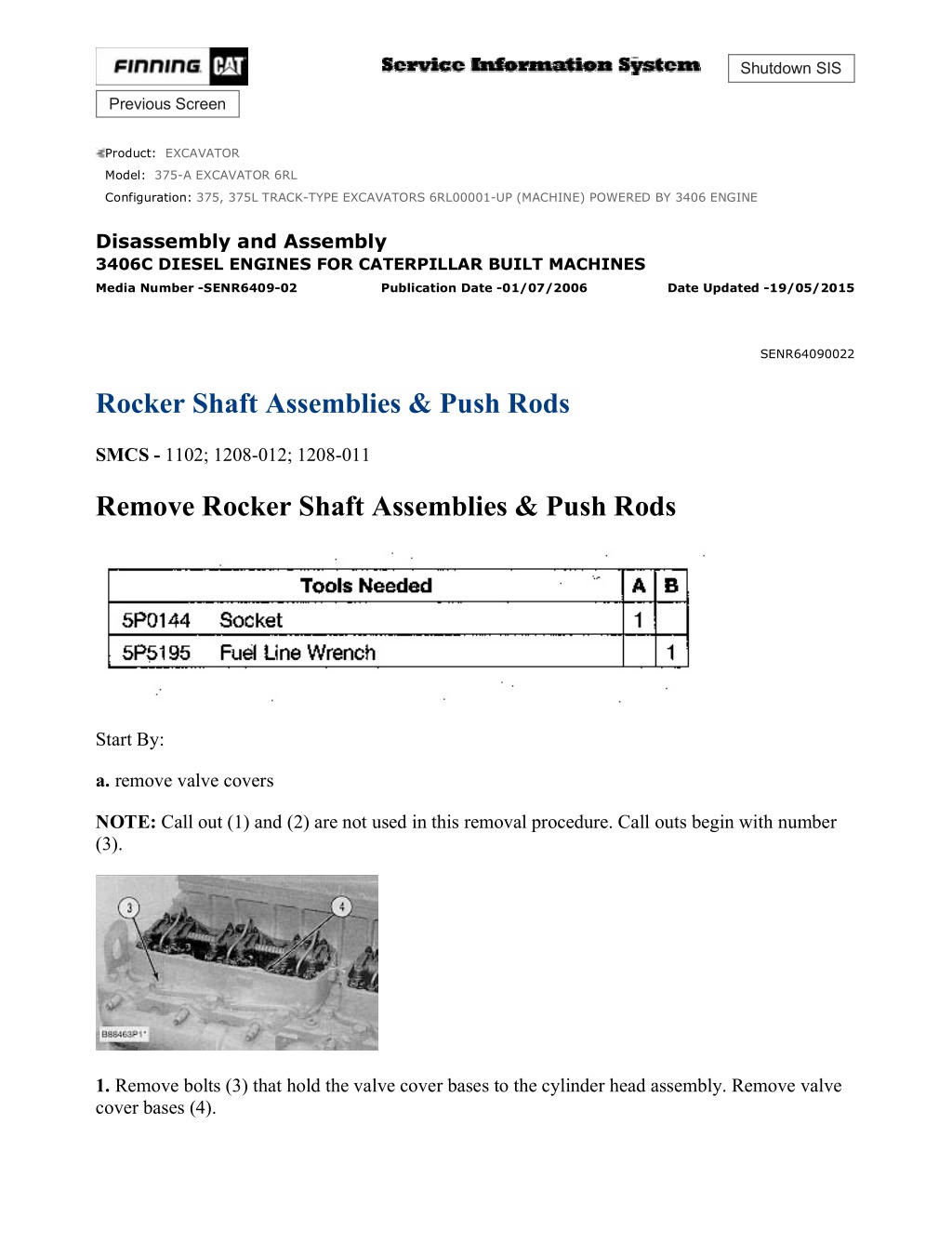
375, 375L TRACK-TYPE EXCAVATORS 6RL00001-UP (MACHINE) POWERED ... 1/6 Shutdown SIS Previous Screen Product: EXCAVATOR Model: 375-A EXCAVATOR 6RL Configuration: 375, 375L TRACK-TYPE EXCAVATORS 6RL00001-UP (MACHINE) POWERED BY 3406 ENGINE Disassembly and Assembly 3406C DIESEL ENGINES FOR CATERPILLAR BUILT MACHINES Media Number -SENR6409-02 Publication Date -01/07/2006 Date Updated -19/05/2015 SENR64090022 Rocker Shaft Assemblies & Push Rods SMCS - 1102; 1208-012; 1208-011 Remove Rocker Shaft Assemblies & Push Rods Start By: a. remove valve covers NOTE: Call out (1) and (2) are not used in this removal procedure. Call outs begin with number (3). 1. Remove bolts (3) that hold the valve cover bases to the cylinder head assembly. Remove valve cover bases (4). https://127.0.0.1/sisweb/sisweb/techdoc/techdoc_print_page.jsp?returnurl=/sis... 2020/12/25
375, 375L TRACK-TYPE EXCAVATORS 6RL00001-UP (MACHINE) POWERED ... 2/6 NOTICE To prevent damage to the fuel injection nozzle, hold adapter assembly (5) in position at the of injection nozzle (6) when fuel line nut (7) is loosened or tightened. https://127.0.0.1/sisweb/sisweb/techdoc/techdoc_print_page.jsp?returnurl=/sis... 2020/12/25
375, 375L TRACK-TYPE EXCAVATORS 6RL00001-UP (MACHINE) POWERED ... 3/6 2. Use Tool (A) and a 7/8 5P0328 Crow Foot ( in) to loosen the fuel injection line nut at the nozzle end. 3. Use Tool (B) to loosen the nut at the fuel injection line adapter end. Remove inner fuel injection lines (8). Install caps and plugs on all fuel injection line openings to keep dirt out of the fuel system. 4. Remove bolts (9) that hold the rocker shaft assemblies to the cylinder head assembly. 5. Remove rocker shaft assemblies (10). 6. Put identification marks on the push rods as to their location in the engine. Remove push rods (11). https://127.0.0.1/sisweb/sisweb/techdoc/techdoc_print_page.jsp?returnurl=/sis... 2020/12/25
https://www.ebooklibonline.com Hello dear friend! Thank you very much for reading. Enter the link into your browser. The full manual is available for immediate download. https://www.ebooklibonline.com
375, 375L TRACK-TYPE EXCAVATORS 6RL00001-UP (MACHINE) POWERED ... 4/6 7. Put identification marks on the bridges as to their location in the engine. Remove bridges (12) from the dowels on the cylinder head assembly. Install Rocker Shaft Assemblies & Push Rods 1. Put clean engine oil on the bridges and dowels. NOTE: Install the original bridges in their respective locations. New bridges can be mixed. 2. Install bridges (1) on the bridge dowels. While firmly pressing 0.5 to 4.5 kg (1 to 10 lb) straight down on the top contact surface of the bridge, turn the adjusting screw clockwise until contact is made with the valve stem. Turn the screw an additional 1/31/2 20 to 30 degrees ( to of 1 hex on nut). This will straighten the dowel in the guide and compensate for the slack in the threads. Hold the adjusting screw in this position and tighten the locknut to a torque of 30 4 N m (22 3 lb ft). NOTE: Install the original push rods in their respective locations in the engine. New push rods can be mixed. https://127.0.0.1/sisweb/sisweb/techdoc/techdoc_print_page.jsp?returnurl=/sis... 2020/12/25
375, 375L TRACK-TYPE EXCAVATORS 6RL00001-UP (MACHINE) POWERED ... 5/6 3. Install push rods (2). 4. Put rocker shaft assemblies (3) in position on the cylinder head assembly. 5. Put clean engine oil on the threads of the bolts that hold the rocker shaft assemblies in place. Tighten the bolts first to a torque of 270 25 N m (200 18 lb ft). Start with the bolt in the center of the rocker shaft assembly. Tighten the bolts again to a torque of 450 20 N m (330 15 lb ft). Tighten the bolts again by hand to a torque of 450 20 N m (330 15 lb ft). NOTICE Do not cause damage to the O-ring seals on the inner fuel lines. 6. Install inner fuel injection lines (4). Tighten the fuel injection line adapter nuts (5) to a torque 40 7 N m (30 5 lb ft) with Tool (A). NOTICE Do not let the tops of the fuel nozzles turn when the fuel lines are tightened. The nozzles will be damaged if the top of the nozzles turns in the body. 7. Tighten fuel injection line nut (6) to a torque of 40 7 N m (30 5 lb ft) with Tool (B) and a 7/8 5P0328 ( in) Crow Foot wrench. 8. Make adjustments to the valves until the intake valve clearance is 0.38 mm (.015 in) and the exhaust valve clearance 0.76 mm (.030 in). See the topic "Valve Clearance Setting" in Testing & https://127.0.0.1/sisweb/sisweb/techdoc/techdoc_print_page.jsp?returnurl=/sis... 2020/12/25
375, 375L TRACK-TYPE EXCAVATORS 6RL00001-UP (MACHINE) POWERED ... 6/6 Adjusting Manual SENR6471. Tighten the locknut to a torque of 30 4 N m (22 3 lb ft) and check the adjustments. 9. Install valve cover bases (7) on the cylinder head assembly. Install bolts that hold the valve cover bases in place. Tighten the bolts to a torque of 14 3 N m (10 2 lb ft). End By: a. install valve covers Copyright 1993 - 2020 Caterpillar Inc. Fri Dec 25 13:54:47 UTC+0800 2020 All Rights Reserved. Private Network For SIS Licensees. https://127.0.0.1/sisweb/sisweb/techdoc/techdoc_print_page.jsp?returnurl=/sis... 2020/12/25
375, 375L TRACK-TYPE EXCAVATORS 6RL00001-UP (MACHINE) POWERED ... 1/2 Shutdown SIS Previous Screen Product: EXCAVATOR Model: 375-A EXCAVATOR 6RL Configuration: 375, 375L TRACK-TYPE EXCAVATORS 6RL00001-UP (MACHINE) POWERED BY 3406 ENGINE Disassembly and Assembly 3406C DIESEL ENGINES FOR CATERPILLAR BUILT MACHINES Media Number -SENR6409-02 Publication Date -01/07/2006 Date Updated -19/05/2015 SENR64090023 Rocker Shaft Assemblies SMCS - 1102-015; 1102-016 Disassemble Rocker Shaft Assemblies Start By: a. remove rocker shaft assemblies and push rods 1. Remove retainer (2) from the end of the shafts. 2. Remove the washers and rocker arms (1). 3. Remove pins (6) that hold the brackets to each end of the shaft. NOTE: The center bracket does not have a pin. https://127.0.0.1/sisweb/sisweb/techdoc/techdoc_print_page.jsp?returnurl=/sis... 2020/12/25
375, 375L TRACK-TYPE EXCAVATORS 6RL00001-UP (MACHINE) POWERED ... 2/2 4. Remove bracket (3), rocker arm (4) and spring (5). Assemble Rocker Shaft Assemblies 1. Put clean engine oil on the shaft. 2. Install the bracket and rocker arms for the center bracket. 3. Install spring (1), rocker arm (2) and bracket (3). Install the pin that holds the brackets on each end of the rocker shaft. Install the pin until it extends 12.7 1.0 mm (.50 .04 in) from the surface of the bracket. 4. Install rocker arm (4) on each end of the shaft. Install washers (5) as needed to get an assembled clearance of .030 to 1.40 mm (.0012 to .055 in) at each end of the shaft. Install the retainer on each end of the shaft. End By: a. install rocker shaft assemblies and push rods Copyright 1993 - 2020 Caterpillar Inc. Fri Dec 25 13:55:35 UTC+0800 2020 All Rights Reserved. Private Network For SIS Licensees. https://127.0.0.1/sisweb/sisweb/techdoc/techdoc_print_page.jsp?returnurl=/sis... 2020/12/25
375, 375L TRACK-TYPE EXCAVATORS 6RL00001-UP (MACHINE) POWERED ... 1/7 Shutdown SIS Previous Screen Product: EXCAVATOR Model: 375-A EXCAVATOR 6RL Configuration: 375, 375L TRACK-TYPE EXCAVATORS 6RL00001-UP (MACHINE) POWERED BY 3406 ENGINE Disassembly and Assembly 3406C DIESEL ENGINES FOR CATERPILLAR BUILT MACHINES Media Number -SENR6409-02 Publication Date -01/07/2006 Date Updated -19/05/2015 SENR64090024 Valve Lifters SMCS - 1209-011; 1209-012 Remove Valve Lifters Start By: a. remove valve covers NOTICE https://127.0.0.1/sisweb/sisweb/techdoc/techdoc_print_page.jsp?returnurl=/sis... 2020/12/25
375, 375L TRACK-TYPE EXCAVATORS 6RL00001-UP (MACHINE) POWERED ... 2/7 Do not let the tops of the fuel nozzles turn when the fuel lines are loosened. The nozzles will be damaged if the top of the nozzles turns in the body. 1. Loosen the fuel injection line nut at the nozzle end with tool (A) and a 7/8 5P0328 ( in) Crow Foot Wrench. 2. Loosen the fuel line nut at the fuel injection line adapter with Tool (B). Remove inner fuel injection lines (1). Install caps and plugs on all fuel line openings to keep dirt out of the fuel system. Typical Example NOTE: If necessary, use Tool (D) to turn the engine so the valves do not make contact with the pistons when the valves are opened with Tool (C) to remove the push rods. 3. Put compression on the valve springs with Tool (C), and remove push rods (2). Put identification marks on the push rods as to their location in the engine. 4. Push the push rod end of the rocker arms down. 5. Remove the intake valve lifter with Tool (E) as follows: a. Install 5P2685 Nut (3) and 5P6601 Collet (4) on 5P2408 Outer Handle Assembly (5). b. Install 5P6599 Inner Handle Assembly (6) in 5P2408 Outer Handle Assembly (5). https://127.0.0.1/sisweb/sisweb/techdoc/techdoc_print_page.jsp?returnurl=/sis... 2020/12/25
375, 375L TRACK-TYPE EXCAVATORS 6RL00001-UP (MACHINE) POWERED ... 3/7 Typical Example c. Install Tool (E) in the intake valve lifter. Hold the 5P2408 Outer Handle Assembly and tighten the 5P6599 Inner Handle Assembly until the 5P6601 Collet is tight against the inside of the intake valve lifter. Typical Example d. Remove intake valve lifters (7) from the cylinder block with Tool (E). Put identification marks on the lifters as to their location in the engine. Typical Example 6. Remove the exhaust valve lifters with Tool (E) as follows: a. Install 5P2685 Nut (3) and 5P6601 Collet (4) on 5P2408 Outer Handle Assembly (5). NOTE: The opening in the cylinder head assembly for the intake valve lifter is larger than the opening in the exhaust valve lifter side. The tooling and each valve lifter must be installed and removed from the intake valve lifter side. b. Install the outer handle assembly in the intake valve lifter side of the cylinder head assembly. Slide the flat area of 5P2408 Outer Handle Assembly (5) through the head casting and install the 5P6601 Collet in the exhaust valve lifters. https://127.0.0.1/sisweb/sisweb/techdoc/techdoc_print_page.jsp?returnurl=/sis... 2020/12/25
375, 375L TRACK-TYPE EXCAVATORS 6RL00001-UP (MACHINE) POWERED ... 4/7 Typical Example c. Install 5P6599 Inner Handle Assembly (6) in 5P2408 Outer Handle Assembly (5). Hold the 5P2408 Handle Assembly and tighten the 5P6599 Handle Assembly until the 5P6601 Collet is tight against the inside of the exhaust valve lifter. d. Pull the exhaust valve lifter up until the spring on the exhaust valve lifter is free from the cylinder block. e. Remove the 5P6599 Inner Handle Assembly. Slide the 5P2408 Outer Handle Assembly through the head casting and remove it from the intake valve lifter side of the cylinder head. Typical Example f. Use a magnet and remove exhaust valve lifters (8) from the intake valve lifter side of the cylinder head assembly. Put identification makes on the lifters as to their location in the engine. 7. Remove the guide springs from the lifters. Install Valve Lifters NOTE: Steps 1 and 2 must be done to install intake or exhaust valve lifters. https://127.0.0.1/sisweb/sisweb/techdoc/techdoc_print_page.jsp?returnurl=/sis... 2020/12/25
375, 375L TRACK-TYPE EXCAVATORS 6RL00001-UP (MACHINE) POWERED ... 5/7 NOTICE Make sure guide spring (1) is not damaged or worn. If the guide spring is damaged or worn, replace the guide spring. See Guideline For Reusable Parts, Form No. SEBF8066. 1. Install guide spring (1) on the valve lifters. 2. Put the intake or exhaust valve lifter in position in 5P2395 Holder (5) of Tool (A). Install 5P2685 Nut (4) and 5P2400 Compressor (3) on 5P2408 Outer Handle Assembly (2). Install the 5P2400 Compressor on the lifter over the guide spring. NOTE: Immerse the lifter assembly in engine oil before installing it in the cylinder block lifter bore. NOTE: The opening in the cylinder head assembly for the intake valve lifter is larger than the opening in the exhaust valve lifter side. All tooling and valve lifters must be installed and removed from the intake valve lifter side. Typical Example 3. Install the exhaust valve lifters with Tool (A) as follows: https://127.0.0.1/sisweb/sisweb/techdoc/techdoc_print_page.jsp?returnurl=/sis... 2020/12/25
375, 375L TRACK-TYPE EXCAVATORS 6RL00001-UP (MACHINE) POWERED ... 6/7 NOTE: Be sure to install the original valve lifter in their respective bores. New valve lifters can be mixed. a. Install exhaust valve lifter (6) and the handle assembly in the cylinder head opening on the intake valve lifter side. Slide the flat area of the 5P2408 Outer Handle Assembly through the casting in the cylinder head assembly. Typical Example b. Put the exhaust valve lifter in the valve lifter bore of the cylinder block. Install 5P6599 Inner Handle Assembly (7) in the 5P2408 Outer Handle Assembly and push the exhaust valve lifter from Tool (A). c. Remove the 5P6599 Inner Handle Assembly from the 5P2408 Outer Handle Assembly. Slide the 5P2408 Outer Handle Assembly to the intake valve lifter side of the cylinder head and remove it. 4. Install the intake valve lifters with Tool (A) as follows: NOTE: Be sure to install original valve lifters in their respective bores. New valve lifters can be mixed. a. Install 5P6599 Inner Handle Assembly (7) in the 5P2408 Outer Handle Assembly. b. Install the intake valve lifter into the valve lifter bore of the cylinder block with Tool (A). Use the 5P6599 Inner Handle Assembly to push the lifter from Tool (A). Remove Tool (A). Typical Example NOTICE If necessary use Tool (C) to turn the engine so the valves do not make contact with the pistons when the valves are opened with Tool (B) to install the push rods. https://127.0.0.1/sisweb/sisweb/techdoc/techdoc_print_page.jsp?returnurl=/sis... 2020/12/25
375, 375L TRACK-TYPE EXCAVATORS 6RL00001-UP (MACHINE) POWERED ... 7/7 5. Turn the rocker arms up and use Tool (B) to install push rods (9). NOTICE Do not let the tops of the fuel nozzles turn when the fuel lines are tightened. The nozzles will be damaged if the top of the nozzles turn in the body. 6. Install inner fuel lines (10). Use Tool (D) to tighten the nuts on the adapter assemblies in the cylinder head assembly and use Tool (E) to tighten the nuts on the fuel injection nozzles to a torque of 40 7 N m (30 5 lb ft). End By: a. install valve covers Copyright 1993 - 2020 Caterpillar Inc. Fri Dec 25 13:56:22 UTC+0800 2020 All Rights Reserved. Private Network For SIS Licensees. https://127.0.0.1/sisweb/sisweb/techdoc/techdoc_print_page.jsp?returnurl=/sis... 2020/12/25
375, 375L TRACK-TYPE EXCAVATORS 6RL00001-UP (MACHINE) POWERED ... 1/3 Shutdown SIS Previous Screen Product: EXCAVATOR Model: 375-A EXCAVATOR 6RL Configuration: 375, 375L TRACK-TYPE EXCAVATORS 6RL00001-UP (MACHINE) POWERED BY 3406 ENGINE Disassembly and Assembly 3406C DIESEL ENGINES FOR CATERPILLAR BUILT MACHINES Media Number -SENR6409-02 Publication Date -01/07/2006 Date Updated -19/05/2015 SENR64090025 Fuel Injection Nozzles & Adapters SMCS - 1106-010; 1254 Remove & Install Fuel Injection Nozzles & Adapters Start By: a. remove valve covers https://127.0.0.1/sisweb/sisweb/techdoc/techdoc_print_page.jsp?returnurl=/sis... 2020/12/25
375, 375L TRACK-TYPE EXCAVATORS 6RL00001-UP (MACHINE) POWERED ... 2/3 1. Use Tool (A) and disconnect fuel line (1) at each end. Remove the fuel line from the engine. 2. Use Tool (B) and remove retainer (2) from the adapter. 3. Remove the fuel injection nozzles with Tool (C) as follows: a. Install the 6V6983 Adapter and the 8T3199 Screw into nozzle assembly (3). b. Install the 8T3198 Tube over the 8T3199 Screw. c. Use the 1B4206 Nut on the 8T3199 Screw to pull the fuel injection nozzle (3). 4. Remove compression seal (4) and carbon dam seal (8) from fuel injection nozzle (3). 5. Use Tool (D) and remove adapter (6) from the cylinder head. 6. Remove gasket (7) and seal (5) from adapter (6). NOTE: The following steps are for the installation of the fuel injection nozzles and adapters. https://127.0.0.1/sisweb/sisweb/techdoc/techdoc_print_page.jsp?returnurl=/sis... 2020/12/25
375, 375L TRACK-TYPE EXCAVATORS 6RL00001-UP (MACHINE) POWERED ... 3/3 7. Use Tool (E) to clean the bore in adapter (6). Use an open end wrench or tap driver to turn Tool (E). 8. Inspect seal (5) for damage or wear. Replace the seal if necessary. 9. Put washer (7) and seal (5) in position on adapter (6). 10. Put liquid soap in the bores of the cylinder head and on seals (5) in the adapters. 11. Put 5P3931 Anti-Seize Compound on the threads of adapter (6) and install the adapter in the cylinder head assembly. 12. Use Tool (D) and tighten the adapter to a torque of 205 14 N m (150 10 lb ft). NOTICE Make sure the correct compression seal washer (4) is used when the nozzle assembly is installed in the adapter. Only copper washers are to be used with this adapter. 13. Install compression seal washer (4) and use Tool (F) to install carbon dam seal (8) on the fuel injection nozzle. 14. Put fuel injection nozzle (3) in position in the adapter and install retainer (2). 15. Use Tool (B) to tighten retainer (2) to a torque of 48 7 N m (35 5 lb ft). 16. Install fuel line (1). Tighten the nuts on the fuel line with Tool (A) to a torque of 40 7 N m (30 5 lb ft). End By: a. install valve covers Copyright 1993 - 2020 Caterpillar Inc. Fri Dec 25 13:57:10 UTC+0800 2020 All Rights Reserved. Private Network For SIS Licensees. https://127.0.0.1/sisweb/sisweb/techdoc/techdoc_print_page.jsp?returnurl=/sis... 2020/12/25
375, 375L TRACK-TYPE EXCAVATORS 6RL00001-UP (MACHINE) POWERED ... 1/4 Shutdown SIS Previous Screen Product: EXCAVATOR Model: 375-A EXCAVATOR 6RL Configuration: 375, 375L TRACK-TYPE EXCAVATORS 6RL00001-UP (MACHINE) POWERED BY 3406 ENGINE Disassembly and Assembly 3406C DIESEL ENGINES FOR CATERPILLAR BUILT MACHINES Media Number -SENR6409-02 Publication Date -01/07/2006 Date Updated -19/05/2015 SENR64090026 Cylinder Head Assembly SMCS - 1100-011; 1100-012 Remove Cylinder Head Assembly Start By: a. remove rocker shaft assemblies and push rods b. remove water temperature regulator c. remove aftercooler housing d. remove fuel injection lines e. remove exhaust manifold Typical Example 1. Remove bolts (1) from the alternator bracket. 2. Remove the bolts that hold plate (3) and remove the plate. 3. Disconnect water line (2) from the air compressor. NOTE: Turn the water line tee toward the lifting bracket in order to provide clearance to remove the head bolt. https://127.0.0.1/sisweb/sisweb/techdoc/techdoc_print_page.jsp?returnurl=/sis... 2020/12/25
375, 375L TRACK-TYPE EXCAVATORS 6RL00001-UP (MACHINE) POWERED ... 2/4 4. Remove bolts (4) and (5) that hold the cylinder head assembly to the cylinder block. 5. Fasten a hoist and remove the cylinder head assembly. The weight is approximately 135 kg (300 lb). NOTICE Do not put the cylinder head assembly down on a flat surface. This can cause damage to the fuel injection valves. 6. Remove the gasket and seals from the spacer plate. Install Cylinder Head Assembly NOTE: Be sure a new gasket has been installed between the spacer plate and the cylinder block. See topic, "Remove & Install Spacer Plate". 1. Thoroughly clean the spacer plate and the bottom surface of the cylinder head assembly. Install a new head gasket, new seals (1) and two O-ring seals (2). 2. Fasten a hoist and put the cylinder head assembly (3) in position on the cylinder block. 3. Tighten the bolts in sequence shown in Illustration D11970. https://127.0.0.1/sisweb/sisweb/techdoc/techdoc_print_page.jsp?returnurl=/sis... 2020/12/25
375, 375L TRACK-TYPE EXCAVATORS 6RL00001-UP (MACHINE) POWERED ... 3/4 (1) Large bolts (3/4 inch). Put 6V4876 Molycoat Paste Lubricant on bolt threads and between washers and underside of bolt heads. (2) Small bolts (3/8 inch). See Step 4h. 4. Install the cylinder head bolts and washers. Tighten the bolts in sequence shown. a. Tighten bolts 1 through 14 in number sequence to 270 25 N m (200 20 lb ft). b. Tighten bolts 1 through 14 in number sequence to 470 20 N m (345 15 lb ft). c. Tighten bolts 1 through 14 in number sequence again to 470 20 N m (345 15 lb ft). d. Install the rocker arm shafts for the engine valves and the remaining (3/4 in) bolts and/or compression brake studs. e. Tighten bolts 15 through 26 in number sequence to 270 25 N m (200 20 lb ft). f. Tighten bolts 15 through 26 in number sequence to 450 20 N m (330 15 lb ft). g. Tighten bolts 15 through 26 in number sequence again to 450 20 N m (330 15 lb ft). h. Tighten the thirteen small bolts (2) to 45 7 N m (33 5 lb ft). 5. Make an adjustment to the valves to have a clearance of 0.38 mm (.015 in) for intake and 0.76 mm (.030 in) for exhaust. Tighten the locknuts for the valve adjustment screws to a torque of 28 4 N m (21 3 lb ft). 6. Install the valve cover bases and the inner fuel lines. See topic, "Install Rocker Shaft Assemblies & Push Rods". 7. Install the valve covers. See topic, "Install Valve Covers". Typical Example 8. Install plate (4). https://127.0.0.1/sisweb/sisweb/techdoc/techdoc_print_page.jsp?returnurl=/sis... 2020/12/25
375, 375L TRACK-TYPE EXCAVATORS 6RL00001-UP (MACHINE) POWERED ... 4/4 9. Connect the water line to the air compressor. 10. Install bolts (5) for the alternator bracket. End By: a. install exhaust manifold b. install fuel injection lines c. install aftercooler housing d. install water temperature regulator e. install rocker shaft assemblies and push rods Copyright 1993 - 2020 Caterpillar Inc. Fri Dec 25 13:57:58 UTC+0800 2020 All Rights Reserved. Private Network For SIS Licensees. https://127.0.0.1/sisweb/sisweb/techdoc/techdoc_print_page.jsp?returnurl=/sis... 2020/12/25
375, 375L TRACK-TYPE EXCAVATORS 6RL00001-UP (MACHINE) POWERED ... 1/2 Shutdown SIS Previous Screen Product: EXCAVATOR Model: 375-A EXCAVATOR 6RL Configuration: 375, 375L TRACK-TYPE EXCAVATORS 6RL00001-UP (MACHINE) POWERED BY 3406 ENGINE Disassembly and Assembly 3406C DIESEL ENGINES FOR CATERPILLAR BUILT MACHINES Media Number -SENR6409-02 Publication Date -01/07/2006 Date Updated -19/05/2015 SENR64090027 Spacer Plate SMCS - 1221-011; 1221-012 Remove Spacer Plate Start By: a. remove cylinder head assembly 1. Remove spacer plate (1) from the cylinder block. NOTICE Do not cause damage to the dowels. 2. Remove the spacer plate gasket and two O-ring seals. Install Spacer Plate https://127.0.0.1/sisweb/sisweb/techdoc/techdoc_print_page.jsp?returnurl=/sis... 2020/12/25
375, 375L TRACK-TYPE EXCAVATORS 6RL00001-UP (MACHINE) POWERED ... 2/2 1. Thoroughly clean the spacer plate and cylinder block surface. Install two O-ring seals (1) in the cylinder block. NOTICE Both surfaces of the spacer plate, top of cylinder block and both sides of the spacer plate gasket must be clean and dry. Gasket adhesives or other substances must not be used on these surfaces. 2. Install a new gasket between the spacer plate and cylinder block. Put spacer plate (2) in position on the cylinder block. 3. Check cylinder liner projection. See topic, "Install Cylinder Liners". End By: a. install cylinder head assembly Copyright 1993 - 2020 Caterpillar Inc. Fri Dec 25 13:58:45 UTC+0800 2020 All Rights Reserved. Private Network For SIS Licensees. https://127.0.0.1/sisweb/sisweb/techdoc/techdoc_print_page.jsp?returnurl=/sis... 2020/12/25
375, 375L TRACK-TYPE EXCAVATORS 6RL00001-UP (MACHINE) POWERED ... 1/3 Shutdown SIS Previous Screen Product: EXCAVATOR Model: 375-A EXCAVATOR 6RL Configuration: 375, 375L TRACK-TYPE EXCAVATORS 6RL00001-UP (MACHINE) POWERED BY 3406 ENGINE Disassembly and Assembly 3406C DIESEL ENGINES FOR CATERPILLAR BUILT MACHINES Media Number -SENR6409-02 Publication Date -01/07/2006 Date Updated -19/05/2015 SENR64090028 Valves SMCS - 1105-011; 1105-012 Remove Valves Start By: a. remove cylinder head assembly 1. Use Tool (A) to compress springs (1). 2. Remove the locks. 3. Remove Tool (A), the valve, the rotocoil, and the spring. NOTE: If a valve can be used again, put identification on the valve for location at installation. https://127.0.0.1/sisweb/sisweb/techdoc/techdoc_print_page.jsp?returnurl=/sis... 2020/12/25
375, 375L TRACK-TYPE EXCAVATORS 6RL00001-UP (MACHINE) POWERED ... 2/3 4. Use Tool (B) to check spring force. The specifications for the spring are given in Specifications Manual, SENR6470. 5. Do Steps 1 through 4 again for the remainder of the valves. Install Valves 1. Put clean engine oil on the valve stem. Install washer (3), spring (2), rotocoil (1) and the valve. 2. Use Tool (A) to compress the spring. 3. Install locks (4) with the thick end up. Locks can be thrown from valve when compressor is released, if they are not in their correct position on the valve stem. https://127.0.0.1/sisweb/sisweb/techdoc/techdoc_print_page.jsp?returnurl=/sis... 2020/12/25
Suggest: If the above button click is invalid. Please download this document first, and then click the above link to download the complete manual. Thank you so much for reading
375, 375L TRACK-TYPE EXCAVATORS 6RL00001-UP (MACHINE) POWERED ... 3/3 4. Remove the compressor and hit the valve with a soft faced hammer to be sure locks are in their correct position on the valve. 5. Do Steps 1 through 4 again for the remainder of the valves. End By: a. install cylinder assembly Copyright 1993 - 2020 Caterpillar Inc. Fri Dec 25 13:59:33 UTC+0800 2020 All Rights Reserved. Private Network For SIS Licensees. https://127.0.0.1/sisweb/sisweb/techdoc/techdoc_print_page.jsp?returnurl=/sis... 2020/12/25
375, 375L TRACK-TYPE EXCAVATORS 6RL00001-UP (MACHINE) POWERED ... 1/2 Shutdown SIS Previous Screen Product: EXCAVATOR Model: 375-A EXCAVATOR 6RL Configuration: 375, 375L TRACK-TYPE EXCAVATORS 6RL00001-UP (MACHINE) POWERED BY 3406 ENGINE Disassembly and Assembly 3406C DIESEL ENGINES FOR CATERPILLAR BUILT MACHINES Media Number -SENR6409-02 Publication Date -01/07/2006 Date Updated -19/05/2015 SENR64090029 Valve Seat Inserts SMCS - 1103-010 Remove & Install Valve Seat Inserts Start By: a. remove valves 1. Use Tool (A) to remove the valve seat inserts from the cylinder head. 2. Clean and remove any burrs from the valve seat bores. NOTE: For reconditioning information of the cylinder head, see Service Training Meeting Guide, SESV1202. NOTE: The following steps are for the installation of the valve seat inserts. https://127.0.0.1/sisweb/sisweb/techdoc/techdoc_print_page.jsp?returnurl=/sis... 2020/12/25
https://www.ebooklibonline.com Hello dear friend! Thank you very much for reading. Enter the link into your browser. The full manual is available for immediate download. https://www.ebooklibonline.com
")
")
")

")
")
")
")
")
")
")
")
")
")
")
")
")
")
")
")
")
")
")
")
")
")
")

")
")