Caterpillar Cat D5M TRACK-TYPE TRACTOR (Prefix 3DR) Service Repair Manual Instant Download (3DR00001 and up)
Please open the website below to get the complete manualnn// n

Download Presentation

Please find below an Image/Link to download the presentation.
The content on the website is provided AS IS for your information and personal use only. It may not be sold, licensed, or shared on other websites without obtaining consent from the author. Download presentation by click this link. If you encounter any issues during the download, it is possible that the publisher has removed the file from their server.
E N D
Presentation Transcript
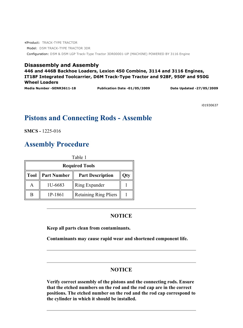
D5M & D5M LGP Track-Type Tractor 3DR00001-UP (MACHINE) POWERED BY ... 1/6 Product: TRACK-TYPE TRACTOR Model: D5M TRACK-TYPE TRACTOR 3DR Configuration: D5M & D5M LGP Track-Type Tractor 3DR00001-UP (MACHINE) POWERED BY 3116 Engine Disassembly and Assembly 446 and 446B Backhoe Loaders, Lexion 450 Combine, 3114 and 3116 Engines, IT18F Integrated Toolcarrier, D6M Track-Type Tractor and 928F, 950F and 950G Wheel Loaders Media Number -SENR3611-18 Publication Date -01/05/2009 Date Updated -27/05/2009 i01930637 Pistons and Connecting Rods - Assemble SMCS - 1225-016 Assembly Procedure Table 1 Required Tools Tool Part Number Part Description Qty A 1U-6683 Ring Expander 1 B 1P-1861 Retaining Ring Pliers 1 NOTICE Keep all parts clean from contaminants. Contaminants may cause rapid wear and shortened component life. NOTICE Verify correct assembly of the pistons and the connecting rods. Ensure that the etched numbers on the rod and the rod cap are in the correct positions. The etched number on the rod and the rod cap correspond to the cylinder in which it should be installed. https://127.0.0.1/sisweb/sisweb/techdoc/techdoc_print_page.jsp?returnurl=/sisw... 2022/5/6
D5M & D5M LGP Track-Type Tractor 3DR00001-UP (MACHINE) POWERED BY ... 2/6 Note: For information on reusability of the pistons, refer to the following list. Guideline For Reusable Parts And Salvage Operations, SEBF8049, "Pistons" Guideline For Reusable Parts And Salvage Operations, SEBF8228, "Procedure to Clean and Inspect One and Two-Piece Pistons in 3114/3116 Engines" Guideline For Reusable Parts And Salvage Operations, SEBF8290, "Visual Inspection of Two-Piece Pistons" Tool Operating Manual, NEHS0775, "Using the 186-0137 Pston Ring Gauge on Steel Crown, Two-Piece Pistons used in 3126 Engines" Note: For information on reusability of the connecting rods, refer to the following list. Guideline For Reusable Parts And Salvage Operations, SEBF8206, "Specificatios for ConnectingRods on 3116 Engines" Guideline For Reusable Parts And Salvage Operations, SEBF8063, "Visual Inspection of Connecting Rods" Guideline For Reusable Parts And Salvage Operations, SEBF8064, "Salvage of Non- Serrated Connecting Rods" Note: For information on reusability of the piston pins, refer to the following list. Guideline For Reusable Parts And Salvage Operations, SEBF8051, "Piston Pins and Retaining Rings" Guideline For Reusable Parts And Salvage Operations, SEBF8303, "Procedure to Inspect Piston Pins" Note: For information on reusability of the rod eye bushing, refer to the following list. Guideline For Reusable Parts And Salvage Operations, SEBF8242, "Verification of Connecting Rod Eye Bushing Retention Using 5P-8639 Connecting Rod Bushing Press Group" Guideline For Reusable Parts And Salvage Operations, SEBF8274, "Using Rod Eye Bushing Installation and Removal Tools" https://127.0.0.1/sisweb/sisweb/techdoc/techdoc_print_page.jsp?returnurl=/sisw... 2022/5/6
D5M & D5M LGP Track-Type Tractor 3DR00001-UP (MACHINE) POWERED BY ... 3/6 Illustration 1 g00610428 1. Check the clearance between the ends of piston rings (5). Refer to the Specifications Manual, "Pistons and Rings". Note: The oil ring must be installed over the spring with the end gap 180 degrees from the oil ring spring joint. 2. Install the oil control piston ring with Tooling (A). The ends of the spring should be rotated 180 degrees from the ring end gap. 3. Install the intermediate piston ring with the side marked "UP-2" toward the top of the piston. Use Tooling (A) in order to install the ring. 4. Install the top piston ring with the side marked "UP-1" toward the top of the piston. Use Tooling (A) in order to install the ring. Illustration 2 g00610498 5. Replace rod bearing (6) by pressing a new bearing into the connecting rod. Refer to Special Instruction, SEHS7295 for the correct tooling and the correct installation procedure. https://127.0.0.1/sisweb/sisweb/techdoc/techdoc_print_page.jsp?returnurl=/sisw... 2022/5/6
https://www.ebooklibonline.com Hello dear friend! Thank you very much for reading. Enter the link into your browser. The full manual is available for immediate download. https://www.ebooklibonline.com
D5M & D5M LGP Track-Type Tractor 3DR00001-UP (MACHINE) POWERED BY ... 4/6 Illustration 3 g00641764 One piece piston Illustration 4 g00610503 6. This piston is a two-piece assembly. This piston consists of piston crown (7) and piston skirt (8). Inspect bearing (9) in the piston crown (7). The piston crown must be replaced if the piston crown is worn or damaged. Bearing (9) is nonserviceable. https://127.0.0.1/sisweb/sisweb/techdoc/techdoc_print_page.jsp?returnurl=/sisw... 2022/5/6
D5M & D5M LGP Track-Type Tractor 3DR00001-UP (MACHINE) POWERED BY ... 5/6 Illustration 5 g00678083 7. Position piston (1) on connecting rod (3). Coat piston pin (4) with clean engine oil and install piston pin (4). Illustration 6 g00678081 8. Use Tooling (B) to install the retaining ring. Illustration 7 g00610426 9. Ensure that retainer rings (2) are in the grooves of piston (1). End By: https://127.0.0.1/sisweb/sisweb/techdoc/techdoc_print_page.jsp?returnurl=/sisw... 2022/5/6
D5M & D5M LGP Track-Type Tractor 3DR00001-UP (MACHINE) POWERED BY ... 6/6 a. Install the pistons and the connecting rods. Refer to Disassembly and Assembly, "Piston and Connecting Rods - Install". https://127.0.0.1/sisweb/sisweb/techdoc/techdoc_print_page.jsp?returnurl=/sisw... 2022/5/6
D5M & D5M LGP Track-Type Tractor 3DR00001-UP (MACHINE) POWERED BY ... 1/6 Product: TRACK-TYPE TRACTOR Model: D5M TRACK-TYPE TRACTOR 3DR Configuration: D5M & D5M LGP Track-Type Tractor 3DR00001-UP (MACHINE) POWERED BY 3116 Engine Disassembly and Assembly 446 and 446B Backhoe Loaders, Lexion 450 Combine, 3114 and 3116 Engines, IT18F Integrated Toolcarrier, D6M Track-Type Tractor and 928F, 950F and 950G Wheel Loaders Media Number -SENR3611-18 Publication Date -01/05/2009 Date Updated -27/05/2009 i03478580 Pistons and Connecting Rods - Install SMCS - 1225-012 Installation Procedure Table 1 Required Tools Tool Part Number Part Description Qty Piston Ring Compressor (1) 187-1462 1 A 173-5529 Piston Ring Compressor (2) 1 B 4C-5593 Anti-Seize Compound 1 ( 1 ) Used for 3114 and 3116 Engines ( 2 ) Used for 3126 Engines NOTICE Keep all parts clean from contaminants. Contaminants may cause rapid wear and shortened component life. Note: For information on reusability of the pistons, refer to the following list. Guideline For Reusable Parts And Salvage Operations, SEBF8049, "Pistons" https://127.0.0.1/sisweb/sisweb/techdoc/techdoc_print_page.jsp?returnurl=/sisw... 2022/5/6
D5M & D5M LGP Track-Type Tractor 3DR00001-UP (MACHINE) POWERED BY ... 2/6 Guideline For Reusable Parts And Salvage Operations, SEBF8290, "Visual Inspection of Two-Piece Pistons" Tool Operating Manual, NEHS0775, "Using the 186-0190 Piston Ring Gauge on Steel Crown, Two-Piece Pistons used in 3126 and 3126B Engines" Note: For information on reusability of the connecting rods, refer to the following list. Guideline For Reusable Parts And Salvage Operations, SEBF8063, "Visual Inspection of Connecting Rods" Guideline For Reusable Parts And Salvage Operations, SEBF8064, "Salvage of Non- Serrated Connecting Rods" Note: For information on reusability of the piston pins, refer to the following list. Guideline For Reusable Parts And Salvage Operations, SEBF8051, "Piston Pins and Retaining Rings" Guideline For Reusable Parts And Salvage Operations, SEBF8303, "Procedure to Inspect Piston Pins" Note: For information on reusability of the rod eye bushing, refer to the following list. Guideline For Reusable Parts And Salvage Operations, SEBF8242, "Verification of Connecting Rod Eye Bushing Retention Using 5P-8639 Connecting Rod Bushing Press Group" Guideline For Reusable Parts And Salvage Operations, SEBF8274, "Using Rod Eye Bushing Installation and Removal Tools" Illustration 1 g00678193 1. Install the bolts (5) and the upper half of connecting rod bearing (4) . Ensure that the bearing tab engages with the slot in connecting rod (3) . https://127.0.0.1/sisweb/sisweb/techdoc/techdoc_print_page.jsp?returnurl=/sisw... 2022/5/6
D5M & D5M LGP Track-Type Tractor 3DR00001-UP (MACHINE) POWERED BY ... 3/6 Illustration 2 g00678195 2. Install the lower half of connecting rod bearing (4) . Ensure that the bearing tab engages with the slot in connecting rod cap (2) . 3. Place clean engine oil on the following items: the pistons, the piston rings, the cylinder bore, the upper half of the connecting rod bearing and the lower half of the connecting rod bearing. NOTICE Install short pieces of rubber hose over both connecting rod bolts in order to protect the crankshaft from the threaded portion of the connecting rod bolts. Illustration 3 g00746584 4. Install short pieces of rubber hose (6) over both connecting rod bolts. https://127.0.0.1/sisweb/sisweb/techdoc/techdoc_print_page.jsp?returnurl=/sisw... 2022/5/6
D5M & D5M LGP Track-Type Tractor 3DR00001-UP (MACHINE) POWERED BY ... 4/6 Illustration 4 g00634923 Note: Each piston ring end gap must be positioned 120 degrees from each other. 5. Install Tooling (A) in order to compress the piston rings. 6. With the number one crankshaft throw at the bottom center, install the piston and connecting rod in the engine. Ensure that the proper piston and connecting rod are in the corresponding cylinder with the bearing retainer notch toward the right side of the engine. Note: The etched number on the connecting rod must be on the right side of the engine in the corresponding cylinder. 7. Line up the piston and the connecting rod with the crankshaft. Use a soft hammer and tap the piston into the cylinder bore until Tooling (A) comes off of the piston. 8. Use a soft hammer in order to tap the piston into the cylinder bore while you guide the connecting rod onto the crankshaft. 9. Remove the hoses that were installed in Step 4 from the connecting rod bolts. Illustration 5 g00678200 10. Install connecting rod bearing cap (2) on the connecting rod (3) . Ensure that the number on connecting rod bearing cap (2) matches the number on the connecting rod (3) . Ensure that the numbers are on the same side. https://127.0.0.1/sisweb/sisweb/techdoc/techdoc_print_page.jsp?returnurl=/sisw... 2022/5/6
D5M & D5M LGP Track-Type Tractor 3DR00001-UP (MACHINE) POWERED BY ... 5/6 11. Lubricate connecting rod cap bolts with Tooling (B) . Illustration 6 g00610272 NOTICE Loose connecting rod nuts can result in the separation of the rod cap and result in major engine damage. Note: Later connecting rods will have bolts in place of the bolts and nuts. 12. Install connecting rod cap nuts (1) . Tighten nuts (1) to the torque that is specified in Table 2. Table 2 Torque Specifications Machined Connecting Rods Tighten nuts (1) to a torque of 54 7 N m (40 5 lb ft) plus an additional 60 5 degrees. Fractured Connecting Rods Tighten nuts (1) to a torque of 70 5 N m (52 4 lb ft) plus an additional 120 5 degrees. 13. Repeat Steps 1 through 12 for the remaining pistons and connecting rods. End By: a. Install the piston cooling jets. Refer to Disassembly and Assembly, "Piston Cooling Jets - Remove and Install". https://127.0.0.1/sisweb/sisweb/techdoc/techdoc_print_page.jsp?returnurl=/sisw... 2022/5/6
D5M & D5M LGP Track-Type Tractor 3DR00001-UP (MACHINE) POWERED BY ... 6/6 b. Install the engine oil pump. Refer to Disassembly and Assembly, "Engine Oil Pump - Install". c. Install the cylinder head. Refer to Disassembly and Assembly, "Cylinder Head - Install". https://127.0.0.1/sisweb/sisweb/techdoc/techdoc_print_page.jsp?returnurl=/sisw... 2022/5/6
D5M & D5M LGP Track-Type Tractor 3DR00001-UP (MACHINE) POWERED BY ... 1/3 Product: TRACK-TYPE TRACTOR Model: D5M TRACK-TYPE TRACTOR 3DR Configuration: D5M & D5M LGP Track-Type Tractor 3DR00001-UP (MACHINE) POWERED BY 3116 Engine Disassembly and Assembly 446 and 446B Backhoe Loaders, Lexion 450 Combine, 3114 and 3116 Engines, IT18F Integrated Toolcarrier, D6M Track-Type Tractor and 928F, 950F and 950G Wheel Loaders Media Number -SENR3611-18 Publication Date -01/05/2009 Date Updated -27/05/2009 i03706818 Crankshaft Main Bearings - Remove SMCS - 1203-011 Removal Procedure Table 1 Required Tools Tool Part Number Part Description Qty A 2P-5518 Bearing Tool 1 Start By: a. Remove the engine balancer shaft on 3114 engines. Refer to Disassembly and Assembly, "Engine Balancer Shaft - Remove and Install". b. Remove the engine oil pump. Refer to Disassembly and Assembly, "Engine Oil Pump - Remove". NOTICE Keep all parts clean from contaminants. Contaminants may cause rapid wear and shortened component life. https://127.0.0.1/sisweb/sisweb/techdoc/techdoc_print_page.jsp?returnurl=/sisw... 2022/5/6
D5M & D5M LGP Track-Type Tractor 3DR00001-UP (MACHINE) POWERED BY ... 2/3 Illustration 1 g00610152 1. Remove bolts (1) that hold crankshaft main bearing cap (2). Remove crankshaft main bearing cap (2). 2. Remove the lower half of the crankshaft main bearing from crankshaft main bearing cap (2). Illustration 2 g00516920 NOTICE If the crankshaft is turned in the wrong direction, the tab of the crankshaft main bearing will be pushed between the crankshaft and the cylinder block. this can cause damage to either or both the crankshaft and the cylinder block. Note: Some crankshaft main bearing journals do not have an oil hole. Place a thin piece of soft material that will not damage the journal against the end of the bearing. Ensure that the material is on the opposite side of the bearing tab. Hit the bearing with the soft material until the bearing tab is free from the bearing tab groove in the cylinder block. 3. Use the following steps in order to remove the upper half of crankshaft main bearings: https://127.0.0.1/sisweb/sisweb/techdoc/techdoc_print_page.jsp?returnurl=/sisw... 2022/5/6
D5M & D5M LGP Track-Type Tractor 3DR00001-UP (MACHINE) POWERED BY ... 3/3 a. Turn the crankshaft until Tooling (A) can be installed in the crankshaft journal. Install Tooling (A). b. Turn the crankshaft in order to remove the upper half of the crankshaft main bearing. In order to get the tab out first, the crankshaft must be turned in the correct direction. c. Check the condition of the crankshaft main bearings. Refer to the Guideline For Reusable Parts, SEBF8009, "Main and Connecting Rod Bearings" and Guideline For Reusable Parts, SEBV0544, "Engine Bearings and Crankshafts". https://127.0.0.1/sisweb/sisweb/techdoc/techdoc_print_page.jsp?returnurl=/sisw... 2022/5/6
D5M & D5M LGP Track-Type Tractor 3DR00001-UP (MACHINE) POWERED BY ... 1/4 Product: TRACK-TYPE TRACTOR Model: D5M TRACK-TYPE TRACTOR 3DR Configuration: D5M & D5M LGP Track-Type Tractor 3DR00001-UP (MACHINE) POWERED BY 3116 Engine Disassembly and Assembly 446 and 446B Backhoe Loaders, Lexion 450 Combine, 3114 and 3116 Engines, IT18F Integrated Toolcarrier, D6M Track-Type Tractor and 928F, 950F and 950G Wheel Loaders Media Number -SENR3611-18 Publication Date -01/05/2009 Date Updated -27/05/2009 i06542070 Crankshaft Main Bearings - Install SMCS - 1203-012 Installation Procedure Table 1 Required Tools Tool Part Number Part Description Qty A 2P-5518 Bearing Tool 1 B 8T-5096 Dial Indicator Group 1 NOTICE Keep all parts clean from contaminants. Contaminants may cause rapid wear and shortened component life. Note: For information on the reusability of the crankshaft main bearings, refer to the Guideline For Reusable Parts And Salvage Operations, SEBF8009, "Main and Connecting Rod Bearings". Note: Place clean engine oil on the crankshaft main bearings prior to assembly. The tabs on the back side of the crankshaft main bearings must fit in the grooves of main bearing caps and the cylinder block. https://127.0.0.1/sisweb/sisweb/techdoc/techdoc_print_page.jsp?returnurl=/sisw... 2022/5/6
D5M & D5M LGP Track-Type Tractor 3DR00001-UP (MACHINE) POWERED BY ... 2/4 Illustration 1 g00516920 1. Use Tooling (A) and install the upper halves of the crankshaft main bearings in the cylinder block. Do not put oil on the back of the crankshaft main bearing. Illustration 2 g00610152 2. Install the lower halves of the crankshaft main bearings in crankshaft main bearing caps (2). Do not put oil on the back of the crankshaft main bearing. https://127.0.0.1/sisweb/sisweb/techdoc/techdoc_print_page.jsp?returnurl=/sisw... 2022/5/6
D5M & D5M LGP Track-Type Tractor 3DR00001-UP (MACHINE) POWERED BY ... 3/4 Illustration 3 g00639559 Six-cylinder engine with oil grooves in the cylinder block Illustration 4 g00639623 Six-cylinder engine with no oil grooves in the cylinder block NOTICE Crankshaft main bearing caps should be installed with the part number toward the right side of the engine. Crankshaft main bearing caps are to be identified by stamped numbers 1 through 7 located on the bottom surface. The thrust plate is to be installed in the original position on the crankshaft main bearing. 3. Oil grooves are machined in the saddles of the cylinder blocks of all 3114 engines and earlier 3116 engines. No oil grooves are machined in the saddles of the cylinder block on later 3116 engines and all 3126 engines. 4. Install the bearing caps with the bearing tabs on the same side. A six cylinder engine has an order of 1 through 7 (front to rear). A four cylinder engine has an order of 1 through 5 (front to rear). Place crankshaft main bearing caps (2) in position on the cylinder block. Place clean engine oil or Molylube on the bolt threads and the washer face. Install bolts (1). 5. Tighten bolts (1) to a torque of 54 7 N m (40 5 lb ft). Tighten each bolt (1) for an additional 90 5 degrees (1/4 turn). https://127.0.0.1/sisweb/sisweb/techdoc/techdoc_print_page.jsp?returnurl=/sisw... 2022/5/6
D5M & D5M LGP Track-Type Tractor 3DR00001-UP (MACHINE) POWERED BY ... 4/4 Illustration 5 g00517003 6. Check the end play of the crankshaft with Tooling (B). The end play must be 0.07 mm (0.003 inch) to 0.32 mm (0.013 inch). End By: a. Install the engine oil pump. Refer to Disassembly and Assembly, "Engine Oil Pump - Install". b. Install the engine balancer shaft on 3114 engines. Refer to Disassembly and Assembly, "Engine Balancer Shaft - Remove and Install". https://127.0.0.1/sisweb/sisweb/techdoc/techdoc_print_page.jsp?returnurl=/sisw... 2022/5/6
D5M & D5M LGP Track-Type Tractor 3DR00001-UP (MACHINE) POWERED BY ... 1/3 Product: TRACK-TYPE TRACTOR Model: D5M TRACK-TYPE TRACTOR 3DR Configuration: D5M & D5M LGP Track-Type Tractor 3DR00001-UP (MACHINE) POWERED BY 3116 Engine Disassembly and Assembly 446 and 446B Backhoe Loaders, Lexion 450 Combine, 3114 and 3116 Engines, IT18F Integrated Toolcarrier, D6M Track-Type Tractor and 928F, 950F and 950G Wheel Loaders Media Number -SENR3611-18 Publication Date -01/05/2009 Date Updated -27/05/2009 i01935937 Crankshaft - Remove SMCS - 1202-011 Removal Procedure Start By: a. Remove the cylinder head. Refer to Disassembly and Assembly, "Cylinder Head - Remove". b. Remove the crankshaft seal carrier. Refer to Disassembly and Assembly, "Crankshaft Rear Seal Carrier - Remove and Install". c. Remove the front gear group. Refer to Disassembly and Assembly, "Gear Group (Front) - Remove". d. Remove the piston and the connecting rods. Refer to Disassembly and Assembly, "Piston and Connecting Rods-Remove". NOTICE Keep all parts clean from contaminants. Contaminants may cause rapid wear and shortened component life. NOTICE https://127.0.0.1/sisweb/sisweb/techdoc/techdoc_print_page.jsp?returnurl=/sisw... 2022/5/6
D5M & D5M LGP Track-Type Tractor 3DR00001-UP (MACHINE) POWERED BY ... 2/3 Care must be taken to ensure that fluids are contained during performance of inspection, maintenance, testing, adjusting, and repair of the product. Be prepared to collect the fluid with suitable containers before opening any compartment or disassembling any component containing fluids. Refer to Special Publication, NENG2500, "Dealer Service Tool Catalog" for tools and supplies suitable to collect and contain fluids on Cat products. Dispose of all fluids according to local regulations and mandates. Note: For information on reusability of the crankshaft, refer to the following list. Guideline For Reusable Parts And Salvage Operations, SEBF8041, "Crankshaft Measurement" Guideline For Reusable Parts And Salvage Operations, SEBF8054, "Procedure to Measure and Straighten Bent Crankshafts" Guideline For Reusable Parts And Salvage Operations, SEBF8094, "Procedure to Grind Crankshafts" Guideline For Reusable Parts And Salvage Operations, SEBF8043, "Visual Inspection of Crankshafts" Guideline For Reusable Parts And Salvage Operations, SEBF8039, "Inspection of Crankshafts for Cracks" Guideline For Reusable Parts And Salvage Operations, SEBF8042, "Procedure to Polish Crankshafts" Note: For information on reusability of the crankshaft main bearings, refer to Guideline For Reusable Parts And Salvage Operations, SEBF8009, "Main and Connecting Rod Bearings". Note: For information on reusability of the cylinder block and salvage procedures, refer to the following list. Guideline For Reusable Parts And Salvage Operations, SEBF8192, "Specifications and Salvage for Cylinder Blocks on 3114, 3116, and 3126 Engines" Guideline For Reusable Parts And Salvage Operations, SEBF8261, "Installing a 7C-6208 Cylinder Sleeve in 3114, 3116 Engines and a 107-7604 Cylinder Sleeve in 3126 Engines" Special Instruction, SEHS8869, "Cylinder Block Salvage Procedure Using Belzona Ceramic R Metal" Special Instruction, GMG00981, "Using 1P-3537 Dial Bore Gauge Group to Check Cylinder Bore Size" Special Instruction, SMHS7606, " Use of 1P-4000 Line Boring Tool Group" Special Instruction, SEHS8841, " Using the Ironstitch Procedure for Casting Salvage" https://127.0.0.1/sisweb/sisweb/techdoc/techdoc_print_page.jsp?returnurl=/sisw... 2022/5/6
D5M & D5M LGP Track-Type Tractor 3DR00001-UP (MACHINE) POWERED BY ... 3/3 Special Instruction, SEHS8919, "Salvage Weld Procedure for Cast Iron Cylinder Blocks" Guideline For Reusable Parts And Salvage Operations, SEBF8076, "Specifications to Salvage Cylinder Block Contact Surfaces" Illustration 1 g00625767 Note: The weight of the crankshaft for the 3114 Engine is 37 kg (82 lb). The weight of the crankshaft for 3116 and 3126 Engines is 62 kg (137 lb). 1. Use a suitable lifting device. Remove bolts (2), the washers and main bearing caps (3). Carefully remove crankshaft (1) from the cylinder block. Illustration 2 g00625782 2. Remove upper main bearing (4) from the cylinder block. 3. Remove the main bearings from the main bearing caps. https://127.0.0.1/sisweb/sisweb/techdoc/techdoc_print_page.jsp?returnurl=/sisw... 2022/5/6
D5M & D5M LGP Track-Type Tractor 3DR00001-UP (MACHINE) POWERED BY ... 1/5 Product: TRACK-TYPE TRACTOR Model: D5M TRACK-TYPE TRACTOR 3DR Configuration: D5M & D5M LGP Track-Type Tractor 3DR00001-UP (MACHINE) POWERED BY 3116 Engine Disassembly and Assembly 446 and 446B Backhoe Loaders, Lexion 450 Combine, 3114 and 3116 Engines, IT18F Integrated Toolcarrier, D6M Track-Type Tractor and 928F, 950F and 950G Wheel Loaders Media Number -SENR3611-18 Publication Date -01/05/2009 Date Updated -27/05/2009 i06249742 Crankshaft - Install SMCS - 1202-012 Installation Procedure Table 1 Required Tools Tool Part Number Part Description Qty A 8T-5096 Dial Indicator Group 1 NOTICE Keep all parts clean from contaminants. Contaminants may cause rapid wear and shortened component life. NOTICE Ensure that the crankshaft main bearing tabs engage with the grooves in the block and the crankshaft main bearing cap. Note: For information on reusability of the crankshaft, refer to the following list. https://127.0.0.1/sisweb/sisweb/techdoc/techdoc_print_page.jsp?returnurl=/sisw... 2022/5/6
Suggest: For more complete manuals. Please go to the home page. https://www.ebooklibonline.com If the above button click is invalid. Please download this document first, and then click the above link to download the complete manual. Thank you so much for reading
D5M & D5M LGP Track-Type Tractor 3DR00001-UP (MACHINE) POWERED BY ... 2/5 Guideline For Reusable Parts And Salvage Operations, SEBF8041, "Crankshaft Measurement" Guideline For Reusable Parts And Salvage Operations, SEBF8054, "Procedure to Measure and Straighten Bent Crankshafts" Guideline For Reusable Parts And Salvage Operations, SEBF8094, "Procedure to Grind Crankshafts" Guideline For Reusable Parts And Salvage Operations, SEBF8043, "Visual Inspection of Crankshafts" Guideline For Reusable Parts And Salvage Operations, SEBF8039, "Inspection of Crankshafts for Cracks" Guideline For Reusable Parts And Salvage Operations, SEBF8042, "Procedure to Polish Crankshafts" Note: For information on reusability of the cylinder block and salvage procedures, refer to the following list. Guideline For Reusable Parts And Salvage Operations, SEBF8192, "Specifications and Salvage for Cylinder Blocks on 3114, 3116, and 3126 Engines" Guideline For Reusable Parts And Salvage Operations, SEBF8261, "Installing a 7C-6208 Cylinder Sleeve in 3114, 3116 Engines and a 107-7604 Cylinder Sleeve in 3126 Engines" Special Instruction, SEHS8869, "Cylinder Block Salvage Procedure Using Belzona Ceramic R Metal" Special Instruction, GMG00981, "Using 1P-3537 Dial Bore Gauge Group to Check Cylinder Bore Size" Special Instruction, SMHS7606, " Use of 1P-4000 Line Boring Tool Group" Special Instruction, SEHS8841, " Using the Ironstitch Procedure for Casting Salvage" Special Instruction, SEHS8919, "Salvage Weld Procedure for Cast Iron Cylinder Blocks" Guideline For Reusable Parts And Salvage Operations, SEBF8076, "Specifications to Salvage Cylinder Block Contact Surfaces" 1. Check the condition of the crankshaft main bearings. Refer to the Guideline For Reusable Parts, SEBF8009, "Main and Connecting Rod Bearings" and Guideline For Reusable Parts, SEBV0544, "Engine Bearings and Crankshafts". Note: The number four main bearing in 3114 Engines is the thrust bearing. The number six main bearing in the six cylinder engines is the thrust bearing. 2. Clean the bearing surfaces in the cylinder block for the main bearings. https://127.0.0.1/sisweb/sisweb/techdoc/techdoc_print_page.jsp?returnurl=/sisw... 2022/5/6
D5M & D5M LGP Track-Type Tractor 3DR00001-UP (MACHINE) POWERED BY ... 3/5 Illustration 1 g00678393 3. Install the upper main bearings (4) in the cylinder block. Ensure that the tab on the back side of the bearing engages with the groove in the cylinder block. Apply clean engine oil on the upper main bearing. Do not put engine oil on the back side of the bearing surfaces. Illustration 2 g00610100 Typical example 4. Put clean engine oil on the journals of the crankshaft bearing. Fasten lifting straps and a hoist to crankshaft (1) . Carefully install the crankshaft in the cylinder block. 5. Clean the bearing surface of the main bearing caps. https://127.0.0.1/sisweb/sisweb/techdoc/techdoc_print_page.jsp?returnurl=/sisw... 2022/5/6
https://www.ebooklibonline.com Hello dear friend! Thank you very much for reading. Enter the link into your browser. The full manual is available for immediate download. https://www.ebooklibonline.com
")
")
")

")
")
")
")
")
")
")
")
")
")
")
")
")
")
")
")
")
")
")
")

")
")