Caterpillar Cat 931C AND 931C LGP TRACK LOADER (Prefix 8AF) Service Repair Manual Instant Download (8AF00001 and up)
Please open the website below to get the complete manualnn//

Download Presentation

Please find below an Image/Link to download the presentation.
The content on the website is provided AS IS for your information and personal use only. It may not be sold, licensed, or shared on other websites without obtaining consent from the author. Download presentation by click this link. If you encounter any issues during the download, it is possible that the publisher has removed the file from their server.
E N D
Presentation Transcript
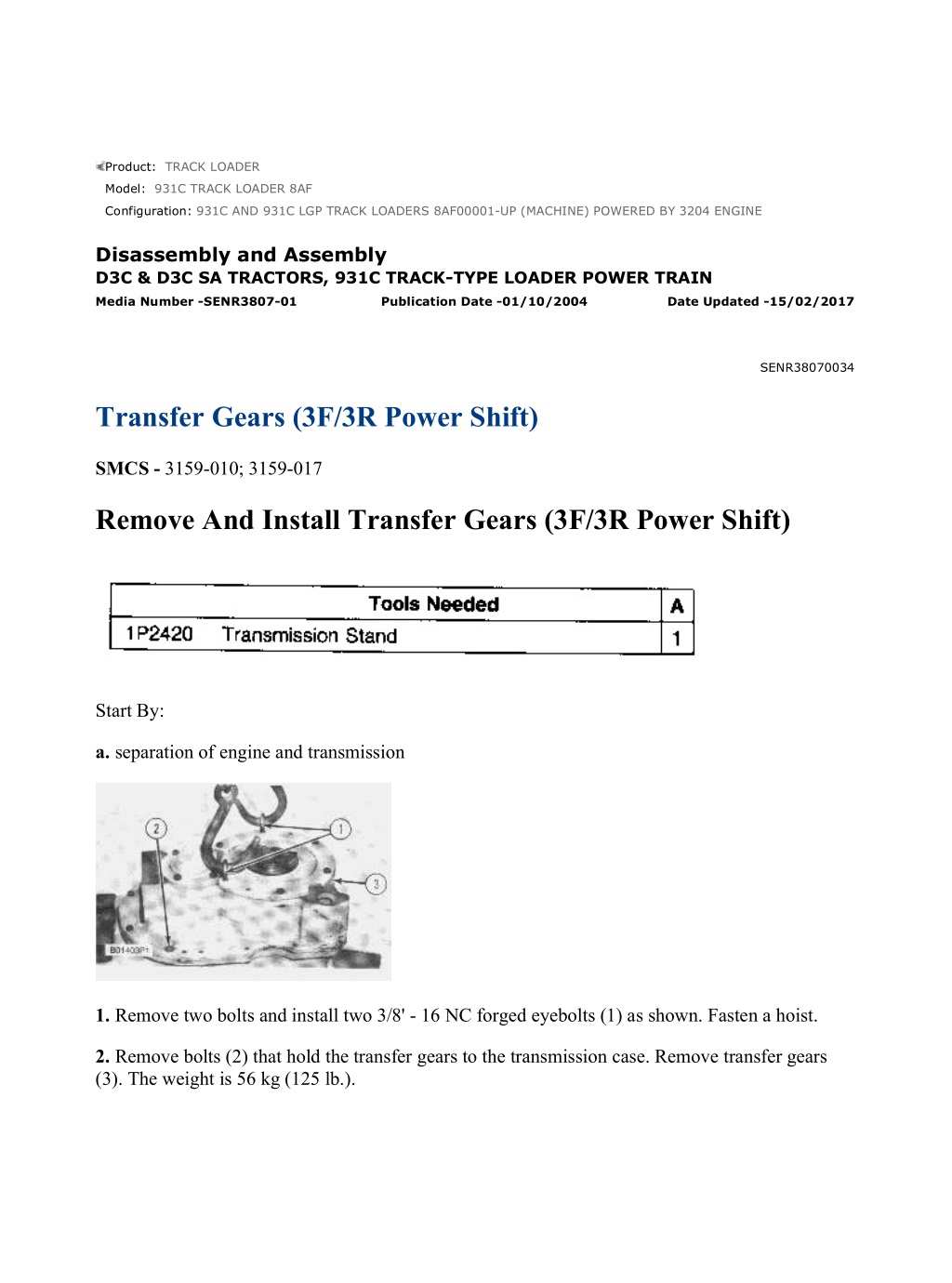
931C AND 931C LGP TRACK LOADERS 8AF00001-UP (MACHINE) POWERED ... 1/7 Product: TRACK LOADER Model: 931C TRACK LOADER 8AF Configuration: 931C AND 931C LGP TRACK LOADERS 8AF00001-UP (MACHINE) POWERED BY 3204 ENGINE Disassembly and Assembly D3C & D3C SA TRACTORS, 931C TRACK-TYPE LOADER POWER TRAIN Media Number -SENR3807-01 Publication Date -01/10/2004 Date Updated -15/02/2017 SENR38070034 Transfer Gears (3F/3R Power Shift) SMCS - 3159-010; 3159-017 Remove And Install Transfer Gears (3F/3R Power Shift) Start By: a. separation of engine and transmission 1. Remove two bolts and install two 3/8' - 16 NC forged eyebolts (1) as shown. Fasten a hoist. 2. Remove bolts (2) that hold the transfer gears to the transmission case. Remove transfer gears (3). The weight is 56 kg (125 lb.). https://127.0.0.1/sisweb/sisweb/techdoc/techdoc_print_page.jsp?returnurl=/sis... 2022/3/15
931C AND 931C LGP TRACK LOADERS 8AF00001-UP (MACHINE) POWERED ... 2/7 3. Remove O-ring seals (4) and (5) from the transmission case. NOTE: The following steps are for installation of transfer gears. 4. Make sure O-ring seals (4) and (5) are in position on the transmission case. 5. Install two 3/8' - 16 NC forged eyebolts as shown and fasten a hoist. Put transfer gears (3) in position on the transmission and install the bolts that hold the transfer gears to the transmission case. End By: a. Connection of engine and transmission Disassemble and Assemble Transfer Gears (3F/3R Power Shift) Start By: a. remove transfer gears 1. Remove bolts (1), plate (2), and gear (3) from the transfer gear case. https://127.0.0.1/sisweb/sisweb/techdoc/techdoc_print_page.jsp?returnurl=/sis... 2022/3/15
931C AND 931C LGP TRACK LOADERS 8AF00001-UP (MACHINE) POWERED ... 3/7 2. Remove snap ring (4) with tool (B). Remove bearing (5) from gear (3). 3. Remove cage (6) from the transfer gear case, and O-ring seal from cage. 4. Remove bearing (7) from the transfer gear case with tooling (A). 5. Remove retaining ring (8) from the transfer gear case. https://127.0.0.1/sisweb/sisweb/techdoc/techdoc_print_page.jsp?returnurl=/sis... 2022/3/15
https://www.ebooklibonline.com Hello dear friend! Thank you very much for reading. Enter the link into your browser. The full manual is available for immediate download. https://www.ebooklibonline.com
931C AND 931C LGP TRACK LOADERS 8AF00001-UP (MACHINE) POWERED ... 4/7 6. Remove yoke (9), O-ring seal (11) and bolts (10) that hold the bearing cage to the transfer gear case. 7. Install two 3/8" -16 NC forcing screws (12) in the bearing cage. Tighten the forcing screws evenly and remove bearing cage (13). 8. Remove shims (14) and O-ring seal (15) from bearing cage (13). 9. Remove lip-type seal (16) from bearing cage (13). https://127.0.0.1/sisweb/sisweb/techdoc/techdoc_print_page.jsp?returnurl=/sis... 2022/3/15
931C AND 931C LGP TRACK LOADERS 8AF00001-UP (MACHINE) POWERED ... 5/7 10. Remove bearing cup (17) from bearing cage (13). 11. Remove gear (18) from the transfer gear case. 12. Remove bearing cones (19) and (20) from gear (18). 13. Remove bearing cup (21) from the transfer gear case. NOTE: The following steps are for assembly of the transfer gears. 14. Inspect all parts for damage and make replacements if needed. 15. Lower the temperature of bearing cup (21). Install bearing cup in the transfer gear case. https://127.0.0.1/sisweb/sisweb/techdoc/techdoc_print_page.jsp?returnurl=/sis... 2022/3/15
931C AND 931C LGP TRACK LOADERS 8AF00001-UP (MACHINE) POWERED ... 6/7 16. Heat bearing cones (19) and (20) to a maximum temperature of 135 C (275 F). Install bearing cones on gear (18). 17. Install gear (18) in the transfer gear case. 18. Lower the temperature of bearing cup (17). Install bearing cup in bearing cage (13). 19. Use tooling (A) and install lip-type seal (16) with the lip of the seal toward the inside of the transfer gear case. Put clean oil on the lip of the seal. 20. Put bearing cage (13) in position on the transfer gear case without the O-ring seal and shims. Install four bolts across from each other as shown. Turn the gear while the bolts are tightened to a torque of 1.1 N m (10 lb.in.). Measure the gap at the bolt location with feeler gauge (22). 21. Install shims (14) that are the same thickness as the average gap measured plus 0.10 0.05 mm (.004 .002 in.). 22. Install O-ring seal (15) on the bearing cage. Put bearing cage (13) in position on the transfer gear case and install the bolts (10). https://127.0.0.1/sisweb/sisweb/techdoc/techdoc_print_page.jsp?returnurl=/sis... 2022/3/15
931C AND 931C LGP TRACK LOADERS 8AF00001-UP (MACHINE) POWERED ... 7/7 23. Install the O-ring seal, yoke (9) and retaining ring (8) in the transfer gear case. 24. Install bearing (7), O-ring seal (23) on cage and install cage (6). 25. Heat bearing (5) to a maximum temperature of 135 C (275 F). Install bearing on gear (3). 26. Install snap ring (4) with tool (B). Install gear (3) and bearing (5) in the transfer gear case. 27. Install plate (2) and bolts (1) to the transfer gear case. End By: a. install transfer gears https://127.0.0.1/sisweb/sisweb/techdoc/techdoc_print_page.jsp?returnurl=/sis... 2022/3/15
931C AND 931C LGP TRACK LOADERS 8AF00001-UP (MACHINE) POWERED ... 1/7 Product: TRACK LOADER Model: 931C TRACK LOADER 8AF Configuration: 931C AND 931C LGP TRACK LOADERS 8AF00001-UP (MACHINE) POWERED BY 3204 ENGINE Disassembly and Assembly D3C & D3C SA TRACTORS, 931C TRACK-TYPE LOADER POWER TRAIN Media Number -SENR3807-01 Publication Date -01/10/2004 Date Updated -15/02/2017 SENR38070035 Torque Converter (3F/3R Power Shift) SMCS - 3101-017; 3101-010 Remove And Install Torque Converter (3F/3R Power Shift) Start By: a. remove transfer gears b. remove transmission hydraulic control valves c. remove transmission oil pump and pump drive NOTE: If problems are experienced when removing or installing the planetary group and torque converter using the procedure described below, use the alternate method that follows this procedure. 1. Remove two bolts and install two 3/8" - 16 NC forged eyebolts (1) in the torque converter. Fasten a hoist. https://127.0.0.1/sisweb/sisweb/techdoc/techdoc_print_page.jsp?returnurl=/sis... 2022/3/15
931C AND 931C LGP TRACK LOADERS 8AF00001-UP (MACHINE) POWERED ... 2/7 2. Remove bolt (2) from each side of the transmission case that holds the planetary group in place. 3. Remove the torque converter and planetary group from the transmission case. The weight is 158 kg (350 lb.). Remove the transmission case from tool (A). 4. Put the planetary group and torque converter in place on tool (A). 5. Remove bolts (4) that hold the torque converter to the planetary group. Remove torque converter (3). The weight is 36 kg (80 lb.). NOTE: The following steps are for installation of the torque converter. 6. Fasten a hoist to eyebolts (1) and put torque converter (3) in position on the planetary group. 7. Install bolts (4) that hold the torque converter to the planetary group. 8. Remove the planetary group and torque converter from tool (A). Fasten a hoist and put the transmission case in place on tool (A). Fasten a hoist and put the planetary group and torque converter in position in the transmission case. 9. Install bolt (2) on each side of the transmission case that holds the planetary group and torque converter in place. Tighten the bolts to a torque of 115 7 N m (85 5 lb.ft.). 10. Remove the eyebolts and install the two bolts. End By: a. install transmission oil pump and pump drive b. install transmission hydraulic control valves c. install transfer gears Remove And Install Torque Converter (3F/3R Power Shift) (Alternate Method) Start By: https://127.0.0.1/sisweb/sisweb/techdoc/techdoc_print_page.jsp?returnurl=/sis... 2022/3/15
931C AND 931C LGP TRACK LOADERS 8AF00001-UP (MACHINE) POWERED ... 3/7 a. remove transfer gears b. remove transmission hydraulic control valves c. remove transmission oil pump and pump drive 1. Make sure the planetary group and torque converter are positioned correctly in the transmission case. Install the bolt on each side of the transmission case that holds the planetary group and torque converter in the transmission case. 2. Place the transmission on tooling (A) with the torque converter down. 3. Remove the bolt from each side of the transmission case that holds the planetary group in place. NOTE: As the transmission case and removed, it must be rotated to a position where the case does not interfere with the idler gear 4. Fasten a hoist to the transmission case and remove the case from the planetary group and torque converter. The weight of the transmission case is 100 Kg (220 lb.). 5. Fasten a hoist to the planetary group. Remove the eight bolts that fasten the planetary group to the torque converter and remove the planetary group. The weight of the planetary group is 122 Kg (270 lb.). NOTE: The following steps are for installation of the torque converter. 6. Put the planetary group in position on the torque converter and install the eight bolts that fasten them together. 7. Place the assembled planetary group and torque converter on tooling (A) with the torque converter down. NOTE: As the transmission case is being lowered over the planetary group and torque converter, the case must be rotated and possibly tilted so it does not interfere with the idler gear. 8. Fasten a hoist to the transmission case and put the case in position on the planetary group and torque converter. 9. Install the bolt on each side of the transmission case that holds the planetary group and torque converter in the transmission case. Tighten the two bolts to a torque of 115 7 N m (85 5 lb.ft.). End By: a. install transmission oil pump and pump drive b. install transmission hydraulic control valves c. install transfer gears Disassemble And Assemble Torque Converter (3F/3R Power Shift) Start By: https://127.0.0.1/sisweb/sisweb/techdoc/techdoc_print_page.jsp?returnurl=/sis... 2022/3/15
931C AND 931C LGP TRACK LOADERS 8AF00001-UP (MACHINE) POWERED ... 4/7 a. remove torque converter 1. Remove bolts (1) and cover (2) from the torque converter housing. 2. Remove bolt (3) and retainer (4) from the shaft. 3. Remove bolts (6), impeller (7) and carrier (5) as a unit from the torque converter housing. 4. Remove six bolts (8) and plates (9) that hold the guide assembly (stator) to the carrier. Remove guide assembly (stator) (10). https://127.0.0.1/sisweb/sisweb/techdoc/techdoc_print_page.jsp?returnurl=/sis... 2022/3/15
931C AND 931C LGP TRACK LOADERS 8AF00001-UP (MACHINE) POWERED ... 5/7 5. Remove retaining ring (11) from the carrier. 6. Turn the impeller and carrier over. Remove bolts (12) that hold carrier (5) to impeller (7). Remove carrier (5). 7. Remove bearing (13) from impeller (7). 8. Remove gear (14) from carrier (5). Remove ring (15) from the carrier. https://127.0.0.1/sisweb/sisweb/techdoc/techdoc_print_page.jsp?returnurl=/sis... 2022/3/15
931C AND 931C LGP TRACK LOADERS 8AF00001-UP (MACHINE) POWERED ... 6/7 9. Remove shaft (16) and wheel (turbine) (17) from torque converter housing (18). Remove seal ring (19) and retaining ring (20) from the shaft. 10. Remove spacer (21) and wheel (turbine) (17) from shaft (16). 11. Remove bearing (22) from torque converter housing (18). NOTE: The following steps are for assembly of the torque converter NOTE: See the topic, Torque Converter Clearance Checks, before assembly of torque converter. These clearances must be correct for the torque converter to operate with efficiency. 12. Lower the temperature of bearing (22). Install bearing (22) in the torque converter housing. 13. Install retaining ring (20) on shaft (16) that puts the wheel (turbine) in the correct position on shaft (16). 14. Install wheel (turbine) (17) and spacer (21) on shaft (16). 15. Install shaft (16), wheel (turbine) (17) and spacer as a unit in torque converter housing (18). Install seal ring (19) on the shaft. 16. Install seal ring (15) and gear (14) on carrier (5). https://127.0.0.1/sisweb/sisweb/techdoc/techdoc_print_page.jsp?returnurl=/sis... 2022/3/15
931C AND 931C LGP TRACK LOADERS 8AF00001-UP (MACHINE) POWERED ... 7/7 17. Install bearing (13) in impeller (7). 18. Put carrier (5) and gear in position on impeller (7). Install bolts (12) that hold them together. Tighten the bolts to a torque of 27 3 N m (20 2 lb.ft.). NOTICE Be careful not to let carrier (5) drop from the gear when the unit is turned over. 19. Turn the carrier, gear and impeller over. Install retainer ring (11) that holds the carrier in place. 20. Put guide assembly (stator) (10) in position on the carrier. 21. Install plates (9) and bolts (8) that hold guide assembly (stator) (10) to the carrier. Tighten the bolts to a torque of 27 3 N m (20 2 lb.ft.). 22. Put impeller (7), carrier (5), gear and guide assembly (stator) in position on the torque converter housing as a unit. Install bolts (6) that hold the impeller to the torque converter housing. Tighten the bolts to a torque of 27 3 N m (20 2 lb.ft.). 23. Install retainer (4) and bolt (3) in the shaft. Tighten the bolt to a torque of 110 5 N m (80 4 lb.ft.). 24. Put cover (2) in position on the torque converter housing. Install all the bolts except two 180 apart that hold the cover in place. The two bolt holes will be used to install eyebolts to install the torque converter. End By: a. install torque converter https://127.0.0.1/sisweb/sisweb/techdoc/techdoc_print_page.jsp?returnurl=/sis... 2022/3/15
931C AND 931C LGP TRACK LOADERS 8AF00001-UP (MACHINE) POWERED ... 1/3 Product: TRACK LOADER Model: 931C TRACK LOADER 8AF Configuration: 931C AND 931C LGP TRACK LOADERS 8AF00001-UP (MACHINE) POWERED BY 3204 ENGINE Disassembly and Assembly D3C & D3C SA TRACTORS, 931C TRACK-TYPE LOADER POWER TRAIN Media Number -SENR3807-01 Publication Date -01/10/2004 Date Updated -15/02/2017 SENR38070036 Torque Converter Clearance Checks (3F/3R Power Shift) SMCS - 3101-017; 3101-010 Torque Converter Clearance Checks (3F/3R Power Shift) 1. There must be a minimum radial (running) clearance between the wheel (turbine) and guide assembly (stator). Check the clearance between the wheel (turbine) and guide assembly (stator) as follows: Typical Example a. Put wheel (turbine) (1) on a smooth, flat surface. Install tooling (A) at four positions around the wheel (turbine) as shown. https://127.0.0.1/sisweb/sisweb/techdoc/techdoc_print_page.jsp?returnurl=/sis... 2022/3/15
931C AND 931C LGP TRACK LOADERS 8AF00001-UP (MACHINE) POWERED ... 2/3 Typical Example b. Put guide assembly (stator) (2) in position in the wheel (turbine). Make sure the welded fins in the guide assembly (stator) are not in contact with tooling (A). Typical Example c. Put tooling (B) against the guide assembly (stator) as shown. Move the guide assembly (stator) toward tooling (B) until it makes contact with the inside diameter in the wheel (turbine). Adjust the dial indicator until it is on zero. Slide guide assembly (stator) (2) 180 away from tooling (B) until it makes contact with the other side of the wheel (turbine) (1). Make a record of the dimension measured. d. Make this check at several locations around the wheel (turbine). Make a record of each dimension measured. The largest dimension measured is used for the clearance between the wheel (turbine) and guide assembly (stator). The total clearance measured across the diameter must be 0.30 to 0.46 mm (.012 to .018 in.) with a maximum permissible clearance of 0.76 mm (.030 in.). The radial (running) clearance is half of the dimensions measured. 2. There must be a minimum radial (running) clearance between the guide assembly (stator) and impeller. https://127.0.0.1/sisweb/sisweb/techdoc/techdoc_print_page.jsp?returnurl=/sis... 2022/3/15
931C AND 931C LGP TRACK LOADERS 8AF00001-UP (MACHINE) POWERED ... 3/3 3. Check the clearance between the outside diameter of the inner flange for the guide assembly (stator) and the inside diameter of the impeller flange as follows: a. Put impeller (3) on a flat smooth surface as shown. Install two 12.7 mm (.5 in.) diameter rods (4) 45.7 cm (18 in.) long, across the impeller as shown. Typical Example b. Put guide assembly (stator) (2) in position on the rods. Typical Example c. Put tooling (B) in position as shown. Slide the guide assembly (stator) toward tooling (B) until it makes contact with the inside diameter of the impeller. Adjust the dial indicator until it is on zero. Keep an even pressure on the guide assembly (stator) when it is moved. Move the guide assembly (stator) away from tooling (B) 180 until it makes contact with the other side of the impeller. Make a record of the dimension measured. Make this check at several locations around the impeller and guide assembly (stator). Make a record of each dimension measured. NOTE: Turn the impeller around tool (B) and the guide assembly (stator) when different locations are measured. d. The largest dimension measured is used for the clearance between the guide assembly (stator) and impeller. The total clearance measured across the diameters must be .030 to 0.46 mm (.012 to .018 in.) with a maximum permissible clearance of 0.76 mm (.030 in.). The radial (running) clearance is one half of the dimensions measured. https://127.0.0.1/sisweb/sisweb/techdoc/techdoc_print_page.jsp?returnurl=/sis... 2022/3/15
931C AND 931C LGP TRACK LOADERS 8AF00001-UP (MACHINE) POWERED ... 1/34 Product: TRACK LOADER Model: 931C TRACK LOADER 8AF Configuration: 931C AND 931C LGP TRACK LOADERS 8AF00001-UP (MACHINE) POWERED BY 3204 ENGINE Disassembly and Assembly D3C & D3C SA TRACTORS, 931C TRACK-TYPE LOADER POWER TRAIN Media Number -SENR3807-01 Publication Date -01/10/2004 Date Updated -15/02/2017 SENR38070037 Transmission (3F/3R Power Shift) SMCS - 3150-015; 3150-016 Disassemble Transmission (3F/3R Power Shift) Start By: a. remove torque converter NOTE: Put a mark on the outside of the clutch housings for correct assembly. https://127.0.0.1/sisweb/sisweb/techdoc/techdoc_print_page.jsp?returnurl=/sis... 2022/3/15
931C AND 931C LGP TRACK LOADERS 8AF00001-UP (MACHINE) POWERED ... 2/34 1. Remove bolt (1) that holds the pump drive gear assembly to the transmission. 2. Use two pry bars as shown and remove pump drive gear assembly (2). 3. Remove shaft (3), bearing cone (4), spacer (5), bearing cone (7) and spacer (8) from pump drive gear (6). 4. Remove bearing cups (9) and ring (10) from pump drive gear (6). 5. Remove shaft (11) from the torque converter end of the transmission. https://127.0.0.1/sisweb/sisweb/techdoc/techdoc_print_page.jsp?returnurl=/sis... 2022/3/15
931C AND 931C LGP TRACK LOADERS 8AF00001-UP (MACHINE) POWERED ... 3/34 6. Remove retaining ring (13) with tool (B). Remove bolts (12) and rear manifold (14). 7. Remove retaining ring (15) and bearing (16) from rear manifold (14). 8. Use tooling (C) to hold the piston and top plate in the No. 4 clutch housing. Remove No. 4 clutch housing (17). NOTICE Keep the pistons, clutch disc and plates for the individual clutch in their original sequence and with their respective clutch housings. 9. Remove top plate (18) and piston (19) from No. 4 clutch housing (17). https://127.0.0.1/sisweb/sisweb/techdoc/techdoc_print_page.jsp?returnurl=/sis... 2022/3/15
931C AND 931C LGP TRACK LOADERS 8AF00001-UP (MACHINE) POWERED ... 4/34 10. Remove teflon rings (20) from piston (19). 11. Remove discs (21) and remainder of plates (18) for the No. 4 clutch. 12. Use tool (D) and push the ends of retaining ring (23) together. Remove housing assembly (22) from the ring gear. 13. Remove seal rings (24) from the seal carrier. https://127.0.0.1/sisweb/sisweb/techdoc/techdoc_print_page.jsp?returnurl=/sis... 2022/3/15
931C AND 931C LGP TRACK LOADERS 8AF00001-UP (MACHINE) POWERED ... 5/34 NOTICE Retaining ring (28) holds spring (27) under compression. 14. Put housing assembly (22) in position in a press. Put spring (27) under compression with tool (E) and the press until retaining ring (28) can be removed with tool (B). 15. Remove one spacer (29), spring (27), other spacer (29) and shaft (25) from the housing assembly. 16. Remove piston (26) from the housing assembly. Remove teflon rings (30) and O-ring seal from piston (26). https://127.0.0.1/sisweb/sisweb/techdoc/techdoc_print_page.jsp?returnurl=/sis... 2022/3/15
931C AND 931C LGP TRACK LOADERS 8AF00001-UP (MACHINE) POWERED ... 6/34 NOTICE It will be necessary to break the seal carrier if it is to be removed from the housing. Remove the pin shown from the housing. 17. Remove retaining ring (31) with tool (F). Remove ring gear (32). 18. Remove discs (33) and plates (34) for the No. 5 clutch from the ring gear. https://127.0.0.1/sisweb/sisweb/techdoc/techdoc_print_page.jsp?returnurl=/sis... 2022/3/15
Suggest: For more complete manuals. Please go to the home page. https://www.ebooklibonline.com If the above button click is invalid. Please download this document first, and then click the above link to download the complete manual. Thank you so much for reading
931C AND 931C LGP TRACK LOADERS 8AF00001-UP (MACHINE) POWERED ... 7/34 19. Remove ring (35) and plate (36) from the ring gear. 20. Remove output shaft (37), hub (38) and planetary carrier (39) as a unit. 21. Remove retaining ring (40) with tool (F) that holds hub (38) on the output shaft. Remove hub (38) from the output shaft. 22. Remove output shaft (37) from the planetary carrier (39). 23. Remove bearings (41) from each end of output shaft (37). https://127.0.0.1/sisweb/sisweb/techdoc/techdoc_print_page.jsp?returnurl=/sis... 2022/3/15
931C AND 931C LGP TRACK LOADERS 8AF00001-UP (MACHINE) POWERED ... 8/34 24. Push pins (42) and (45) even with the inside surface of gear (44). Remove plate (43). 25. Turn the planetary carrier over. Remove sun gear (46) from the planetary carrier. 26. Use tooling (D) to push ring (47) toward the inside of the groove in the planetary carrier. Remove planetary carrier (39) from ring gear (44). 27. Remove ring (47) from the planetary carrier. https://127.0.0.1/sisweb/sisweb/techdoc/techdoc_print_page.jsp?returnurl=/sis... 2022/3/15
https://www.ebooklibonline.com Hello dear friend! Thank you very much for reading. Enter the link into your browser. The full manual is available for immediate download. https://www.ebooklibonline.com
")
")
")

")
")
")
")
")
")
")
")
")
")
")
")
")
")
")
")
")
")
")
")

")
")