Caterpillar Cat 931C AND 931C LGP TRACK LOADER (Prefix 7HF) Service Repair Manual Instant Download (7HF00001 and up)
Please open the website below to get the complete manualnn//

Download Presentation

Please find below an Image/Link to download the presentation.
The content on the website is provided AS IS for your information and personal use only. It may not be sold, licensed, or shared on other websites without obtaining consent from the author. Download presentation by click this link. If you encounter any issues during the download, it is possible that the publisher has removed the file from their server.
E N D
Presentation Transcript
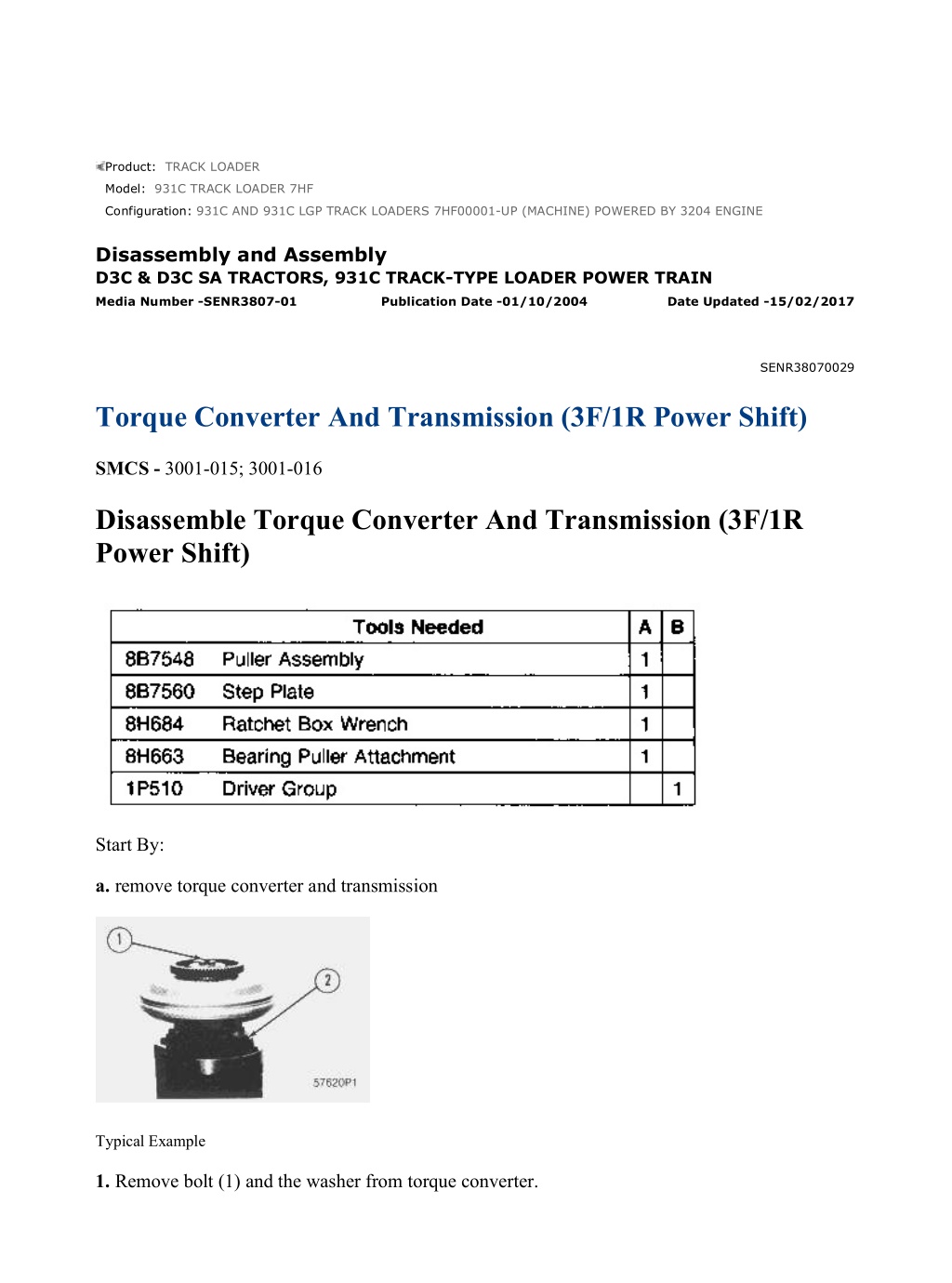
931C AND 931C LGP TRACK LOADERS 7HF00001-UP (MACHINE) POWERED ... 1/14 Product: TRACK LOADER Model: 931C TRACK LOADER 7HF Configuration: 931C AND 931C LGP TRACK LOADERS 7HF00001-UP (MACHINE) POWERED BY 3204 ENGINE Disassembly and Assembly D3C & D3C SA TRACTORS, 931C TRACK-TYPE LOADER POWER TRAIN Media Number -SENR3807-01 Publication Date -01/10/2004 Date Updated -15/02/2017 SENR38070029 Torque Converter And Transmission (3F/1R Power Shift) SMCS - 3001-015; 3001-016 Disassemble Torque Converter And Transmission (3F/1R Power Shift) Start By: a. remove torque converter and transmission Typical Example 1. Remove bolt (1) and the washer from torque converter. https://127.0.0.1/sisweb/sisweb/techdoc/techdoc_print_page.jsp?returnurl=/sis... 2022/3/16
931C AND 931C LGP TRACK LOADERS 7HF00001-UP (MACHINE) POWERED ... 2/14 2. Remove bolts (2) that hold the flange to the manifold. Typical Example 3. Install two 3/8" - 16 NC forged eyebolts (3) in the torque converter and fasten a hoist. 4. Install two of the 3/8" - 16 NC bolts (4) that were removed from torque converter as forcing screws in the flange. Remove the torque converter as a unit. 5. Remove bolts (5) that hold spider (6) on the torque converter. 6. Remove snap rings (7) and (8) and seal ring (9) from the hub. 7. Remove bearing (10) from the hub. 8. Turn the torque converter over. https://127.0.0.1/sisweb/sisweb/techdoc/techdoc_print_page.jsp?returnurl=/sis... 2022/3/16
931C AND 931C LGP TRACK LOADERS 7HF00001-UP (MACHINE) POWERED ... 3/14 Typical Example 9. Remove bolts (11) that hold flange (12) on the hub. Remove flange (12). Remove the seal ring from the flange. 10. Remove the bolts that hold the gear on the torque converter. Remove the gear. 11. Remove bearing (13) from the hub with two bars. 12. Turn the transmission assembly over with a hoist. NOTE: Put a mark on each housing and plate for correct installation. 13. Remove nuts (14) from the bolts that hold the housing together. 14. Install two 3/8" - 16 NC forged eyebolts. Fasten a hoist and remove No. 1 clutch housing (15) and gear as a unit. https://127.0.0.1/sisweb/sisweb/techdoc/techdoc_print_page.jsp?returnurl=/sis... 2022/3/16
https://www.ebooklibonline.com Hello dear friend! Thank you very much for reading. Enter the link into your browser. The full manual is available for immediate download. https://www.ebooklibonline.com
931C AND 931C LGP TRACK LOADERS 7HF00001-UP (MACHINE) POWERED ... 4/14 15. Remove the rings that hold gear (16) and bearing in the clutch housing. Remove the gear from the housing. 16. Remove the bearing race from gear (16) with tooling (A). 17. Remove No. 1 clutch plates (17), discs, springs (18) and ring gear. Remove the seal rings from the piston for No. 1 clutch. 18. Install two 3/8" - 16 NC forged eyebolts (20) in the carrier. 19. Remove No. 1 and reverse carrier (19) as a unit. 20. Remove bolts (21) and washers that hold No. 1 and reverse carrier together. 21. Make two separations of the carriers. https://127.0.0.1/sisweb/sisweb/techdoc/techdoc_print_page.jsp?returnurl=/sis... 2022/3/16
931C AND 931C LGP TRACK LOADERS 7HF00001-UP (MACHINE) POWERED ... 5/14 22. Remove six planetary gears (22) from the carriers. 23. Remove the washers from each side of the gears. 24. Remove the roller bearings from the inside of each planetary gear. 25. Remove seal ring (23) from the carrier. 26. Remove plate (24), discs, plates, springs (27) and ring gear (25). 27. Remove reverse clutch housing (26). 28. Remove the bearing from the reverse clutch housing with tooling (B). 29. Remove piston (28) from the reverse clutch housing. Remove the seal rings from the piston. https://127.0.0.1/sisweb/sisweb/techdoc/techdoc_print_page.jsp?returnurl=/sis... 2022/3/16
931C AND 931C LGP TRACK LOADERS 7HF00001-UP (MACHINE) POWERED ... 6/14 30. Remove plates (29), discs and springs for the No. 2 clutch. 31. Remove snap rings and gear (31) from the shaft. 32. Remove bolts (32) evenly from sun gear (30). Remove the sun gear. 33. Remove ring gear (33), springs, discs and plates from the clutch housing. Remove the hub from the shaft. 34. Remove the No. 2 clutch housing. Remove clutch piston (34). Remove seal rings (35) and (36) from the piston. 35. Remove the O-ring seal under seal ring (36). https://127.0.0.1/sisweb/sisweb/techdoc/techdoc_print_page.jsp?returnurl=/sis... 2022/3/16
931C AND 931C LGP TRACK LOADERS 7HF00001-UP (MACHINE) POWERED ... 7/14 36. Remove the No. 3 clutch piston. 37. Remove snap ring (37) from the inside manifold. 38. Remove piston housing (38). Remove snap ring (39) and bearing (40) from the piston housing. 39. Remove seal rings (43) from the inside manifold. 40. Remove the shaft and inside manifold (41) from outside manifold (42). 41. Remove the shaft from the inside manifold. Remove the snap ring from the shaft. 42. Remove the bolts that hold the clutch housings together. Assemble Torque Converter And Transmission (3F/1R Power Shift) https://127.0.0.1/sisweb/sisweb/techdoc/techdoc_print_page.jsp?returnurl=/sis... 2022/3/16
931C AND 931C LGP TRACK LOADERS 7HF00001-UP (MACHINE) POWERED ... 8/14 1. Install snap ring (46) on shaft (44). Install the shaft inside manifold (41). 2. Install the shaft and the inside manifold in outside manifold (42). 3. Install bolts (45) that hold the transmission housings together. 4. Install seal rings (43) on the inside manifold. 5. Install bearing (40) and snap ring (39) in the piston housing. 6. Install piston housing (38) over the inside manifold with the notch in the bearing in alignment with ball (47) in the manifold. 7. Install the seal rings on the piston for the No. 3 clutch. 8. Install piston (48) for the No. 3 clutch in the piston housing. https://127.0.0.1/sisweb/sisweb/techdoc/techdoc_print_page.jsp?returnurl=/sis... 2022/3/16
931C AND 931C LGP TRACK LOADERS 7HF00001-UP (MACHINE) POWERED ... 9/14 NOTICE The seal ring (35) with the larger diameter must be installed with the lip of seal ring toward the pressure oil. 9. Install an O-ring and seal ring (36) in the groove with the smallest diameter on the piston for No. 2 clutch. Install seal ring (35) on the piston in the groove with the larger diameter. NOTICE The piston must not be pushed down too far. The seal ring will come out on the bottom side of housing and cause damage to seal ring. 10. Carefully install piston (34) in the housing for the No. 2 clutch so the top of the piston is even with the bottom of the notch in the clutch housing. 11. Install housing (49) for the No. 2 clutch. 12. Install hub (50) on the shaft. 13. Install the snap ring that holds the hub in position. https://127.0.0.1/sisweb/sisweb/techdoc/techdoc_print_page.jsp?returnurl=/sis... 2022/3/16
931C AND 931C LGP TRACK LOADERS 7HF00001-UP (MACHINE) POWERE... 10/14 14. Install the plates, discs and springs (51). 15. Install ring gear (33) over the springs, discs and plates. 16. Install sun gear (30). 17. Install bolts that hold the sun gear on the ring gear. 18. Install the snap rings and small sun gear (31) on the shaft. 19. Install the plates, discs and springs for the No. 2 clutch. 20. Install bearing (52) in the reverse clutch housing with tooling (B). 21. Install the seal rings on the reverse clutch piston with the lip of the seal rings toward the pressure oil. Install the reverse clutch housing. 22. Install the ring for the reverse clutch. https://127.0.0.1/sisweb/sisweb/techdoc/techdoc_print_page.jsp?returnurl=/sis... 2022/3/16
931C AND 931C LGP TRACK LOADERS 7HF00001-UP (MACHINE) POWERE... 11/14 23. Install seal (23) on the carrier. 24. Install washers (55), gear (22), bearings (54) and the spacer on each of the three shafts (53) of the two carriers. 25. Put the carriers together and install the six bolts. 26. Install carrier assembly (19) in ring gear (25) for the reverse clutch. 27. Install the discs, plates (56) and springs (27) for the reverse clutch. 28. Install the plate assembly on reverse clutch housing. NOTE: Be sure the oil hole in plate is in alignment with the oil hole in housing for reverse clutch. https://127.0.0.1/sisweb/sisweb/techdoc/techdoc_print_page.jsp?returnurl=/sis... 2022/3/16
931C AND 931C LGP TRACK LOADERS 7HF00001-UP (MACHINE) POWERE... 12/14 29. Install the ring gear for No. 1 clutch on the carrier. 30. Install plates (17), discs and springs (18) for No. 1 clutch. 31. Install bearing (58) and snap ring (57) in housing for No. 1 clutch. 32. Install the bearing race on gear (16). 33. Install gear (16) through the bearing, and install snap ring (59). 34. Install the seal rings on the piston for No. 1 clutch, with the lip of the seal rings toward the pressure oil. 35. Install the piston for No. 1 clutch in the housing. Hold the piston in the housing with tools (C). https://127.0.0.1/sisweb/sisweb/techdoc/techdoc_print_page.jsp?returnurl=/sis... 2022/3/16
931C AND 931C LGP TRACK LOADERS 7HF00001-UP (MACHINE) POWERE... 13/14 36. Install two 3/8" - 16 NC forged eyebolts in clutch housing. Fasten a hoist and install the clutch housing. 37. Be sure the oil hole in housing is in alignment with hole in plate (24). Put the splines of gear (16) in alignment with splines of the carrier assembly. 38. Install the washers and nuts on the bolts that hold the housing together. 39. Turn the transmission over with a hoist so the converter can be inltalled. NOTE: Be sure the bearing next to spider (6) is installed with the groove toward the outside of the torque converter. 40. Install bearing (39) on each side of the torque converter. 41. Install seal ring (9), lockrings, (7) and (8) that hold the bearing in position on the torque converter. 42. Install spider (6) on the torque converter. 43. Install all of the bolts except two, that hold the spider on the torque converter. Install two 3/8" - 16 NC forged eyebolts in the two holes. Tighten the bolts to a torque of 50 7 N m (37 5 lb.ft.). https://127.0.0.1/sisweb/sisweb/techdoc/techdoc_print_page.jsp?returnurl=/sis... 2022/3/16
931C AND 931C LGP TRACK LOADERS 7HF00001-UP (MACHINE) POWERE... 14/14 Typical Example 44. Position drive gear (60) for the transmission pump on the torque converter, and install eight the bolts that hold it in place. Tighten the bolts to a torque of 50 7 N m (37 5 lb.ft.). 45. Install the seal ring on the flange. 46. Position flange (12) on the dowel pins of the torque converter, and install the four bolts that hold it in place. Tighten the bolts to a torque of 50 7 N m (37 5 lb.ft.). 47. Install the torque converter assembly on the transmission. Install the bolts that hold the flange on the manifold. Remove the two eyebolts and install the two bolts in the spider. 48. Install bolt (1) and the washer on the torque converter. 49. Put oil in all the clutch ports. Use tool (D) and air with pressure of 690 to 1030 kPa (100 to 150 psi) to check the operation of the clutch pistons. There must be approximately 3.18 to 6.35 mm (.125 to .250 in.) of movement in each piston. If a piston does not move, it can have a broken seal or assembled wrong. The transmission must be disassembled to find the cause. End By: a. install torque converter and transmission https://127.0.0.1/sisweb/sisweb/techdoc/techdoc_print_page.jsp?returnurl=/sis... 2022/3/16
931C AND 931C LGP TRACK LOADERS 7HF00001-UP (MACHINE) POWERED ... 1/3 Product: TRACK LOADER Model: 931C TRACK LOADER 7HF Configuration: 931C AND 931C LGP TRACK LOADERS 7HF00001-UP (MACHINE) POWERED BY 3204 ENGINE Disassembly and Assembly D3C & D3C SA TRACTORS, 931C TRACK-TYPE LOADER POWER TRAIN Media Number -SENR3807-01 Publication Date -01/10/2004 Date Updated -15/02/2017 SENR38070030 Transfer Gears (3F/1R Power Shift) SMCS - 3159-010 Remove And Install Transfer Gears (3F/1R Power Shift) Start By: a. remove torque converter and transmission from case 1. Remove the four bolts that fasten cage (1) to the transmission case. Install two 3/8" - 16 NC forcing screws in case (1). Tighten the forcing screws evenly, and remove cage (1) from the transmission case. 2. Remove O-ring seal (2) and roller bearing (3) from cage (1). https://127.0.0.1/sisweb/sisweb/techdoc/techdoc_print_page.jsp?returnurl=/sis... 2022/3/16
931C AND 931C LGP TRACK LOADERS 7HF00001-UP (MACHINE) POWERED ... 2/3 3. Remove the six bolts that fasten cage (4) to the transmission case. Install two 3/8" - 16 NC forcing screws in cage (4). Tighten the forcing screws evenly, and remove cage (4) and the shims from the transmission case. 4. Remove the bearing cup, O-ring seal and lip-type seal from cage (4). 5. Remove output gear (5). 6. Remove bearing cone (6) from each side of output gear (5). 7. Remove bearing cup (7) from the transmission case. NOTE: The following steps are for installation of the transfer gears. 8. Lower the temperature of bearing cup (7), and install it in the transmission case. 9. Heat bearing cones (6) to a maximum temperature of 135 C (275 F), and install them on output gear (5). 10. Install output gear (5) in the transmission case. 11. Lower the temperature of the bearing cup, and install the bearing cup in cage (4). 12. Install the O-ring seal and lip-type seal in cage (4). Install the lip-type seal with the lip toward the inside of the cage. Put clean transmission oil on the seals. https://127.0.0.1/sisweb/sisweb/techdoc/techdoc_print_page.jsp?returnurl=/sis... 2022/3/16
931C AND 931C LGP TRACK LOADERS 7HF00001-UP (MACHINE) POWERED ... 3/3 13. Position the original shims and cage (4) on the transmission case, and install the six bolts that hold them in place. Add or subtract the shims as necessary to obtain an allowable end play of 0.10 0.05 mm (.004 .002 in.) in bearing cones (6). 14. Install roller bearing (3) in cage (1). 15. Install O-ring seal (2) on cage (1). Put clean transmission oil on the O-ring seal. 16. Install cage (1) on the transmission case. End By: a. install torque converter and transmission in case https://127.0.0.1/sisweb/sisweb/techdoc/techdoc_print_page.jsp?returnurl=/sis... 2022/3/16
931C AND 931C LGP TRACK LOADERS 7HF00001-UP (MACHINE) POWERED ... 1/4 Product: TRACK LOADER Model: 931C TRACK LOADER 7HF Configuration: 931C AND 931C LGP TRACK LOADERS 7HF00001-UP (MACHINE) POWERED BY 3204 ENGINE Disassembly and Assembly D3C & D3C SA TRACTORS, 931C TRACK-TYPE LOADER POWER TRAIN Media Number -SENR3807-01 Publication Date -01/10/2004 Date Updated -15/02/2017 SENR38070031 Transmission Oil Pump And Pump Drive Gear (3F/3R Power Shift) SMCS - 3153-010; 3153-017 Remove And Install Transmission Oil Pump And Pump Drive Gear (3F/3R Power Shift) NOTE: This can be done in the machine. Transmission is removed for photo illustration. 1. Disconnect the two oil lines connected to the oil pump. 2. Remove two bolts (1) and remove transmission oil pump (2). https://127.0.0.1/sisweb/sisweb/techdoc/techdoc_print_page.jsp?returnurl=/sis... 2022/3/16
931C AND 931C LGP TRACK LOADERS 7HF00001-UP (MACHINE) POWERED ... 2/4 3. Remove bolt (3) and retainer (4) that hold pump drive gear (5) in place. Remove pump drive gear (5). NOTE: The following steps are for installation of the transmission oil pump and drive gear. 4. Put pump drive gear (5) in place in the transmission and install retainer (4) and bolt (3). 5. Make sure the O-ring seal is in position, and install transmission oil pump (2). Install bolts (1) that hold the pump to the transmission case. Disassemble And Assemble Transmission Oil Pump And Pump Drive Gear (3F/3R Power Shift) Start By: a. remove transmission oil pump and pump drive gear 1. Remove O-ring seal (2) from cover (3), bolts (1) and cover (3) from the pump body. 2. Remove bearings (4) from cover (3). https://127.0.0.1/sisweb/sisweb/techdoc/techdoc_print_page.jsp?returnurl=/sis... 2022/3/16
Suggest: For more complete manuals. Please go to the home page. https://www.ebooklibonline.com If the above button click is invalid. Please download this document first, and then click the above link to download the complete manual. Thank you so much for reading
931C AND 931C LGP TRACK LOADERS 7HF00001-UP (MACHINE) POWERED ... 3/4 3. Remove drive gear (7), driven gear (6) and O-ring seal (5) from the pump body. 4. Remove bearings (8) from pump body (9). 5. Remove spiral lockring (10), shaft (11) and bearing (12) from gear (13). NOTE: The following are assembly steps of the transmission oil pump and drive gear. 6. Make sure all of the parts of the transmission oil pump and pump drive gear are clean. Put clean oil on all the parts of the pump and gear. Inspect all parts for damage and make replacements if needed. 7. Install bearing (12) and shaft (11) in gear (13) with spiral lockring (10) to hold the bearing in place. NOTICE Make sure the joint in both bearings (8) are in the correct location. The location of the joint is an angle of 30 15 from the center line of the two bearing bores in the direction of groove (14) on surface (15). https://127.0.0.1/sisweb/sisweb/techdoc/techdoc_print_page.jsp?returnurl=/sis... 2022/3/16
931C AND 931C LGP TRACK LOADERS 7HF00001-UP (MACHINE) POWERED ... 4/4 8. Install two bearings (8) into pump body (9) with tooling (A) and a press. The distance from the top of the bearing to surface (15) after assembly is 1.50 0.25 mm (.059 .010 in.). 9. Install O-ring seal (5), driven gear (6) and drive gear (7) in pump body (9). NOTICE Make sure the joint in both bearings (4) are in the correct location. The location of the joint is an angle 30 15 from the centerline of the two bearing bores in the direction of groove (16) on surface (17). 10. Install two bearings (4) in cover (3) with tooling (A). The distance from the top of the bearing to surface (17) after assembly is 1.50 0.25 mm (.059 .010 in.). 11. Install O-ring seal (2) on cover (3). Install cover on pump body (9) with bolts (1). NOTE: Pump must turn freely by hand after assembly. End By: a. install transmission oil pump and pump drive gear https://127.0.0.1/sisweb/sisweb/techdoc/techdoc_print_page.jsp?returnurl=/sis... 2022/3/16
https://www.ebooklibonline.com Hello dear friend! Thank you very much for reading. Enter the link into your browser. The full manual is available for immediate download. https://www.ebooklibonline.com
")
")
")

")
")
")
")
")
")
")
")
")
")
")
")
")
")
")
")

")
")