Caterpillar Cat 931C and 931C LGP TRACK LOADER (Prefix 6RF) Service Repair Manual Instant Download (6RF00001 and up)
Please open the website below to get the complete manualnn//

Download Presentation

Please find below an Image/Link to download the presentation.
The content on the website is provided AS IS for your information and personal use only. It may not be sold, licensed, or shared on other websites without obtaining consent from the author. Download presentation by click this link. If you encounter any issues during the download, it is possible that the publisher has removed the file from their server.
E N D
Presentation Transcript
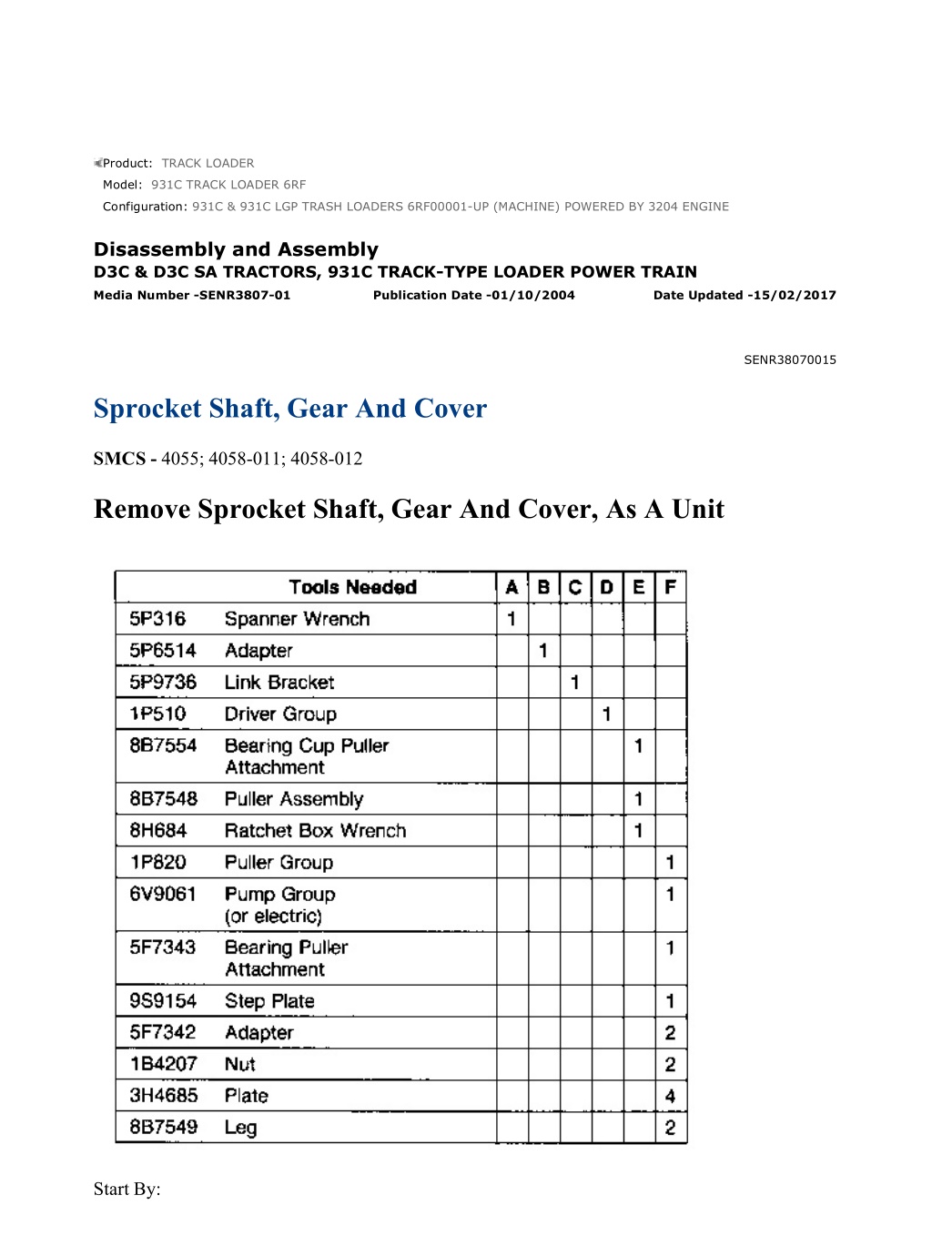
931C & 931C LGP TRASH LOADERS 6RF00001-UP (MACHINE) POWERED BY ... 1/10 Product: TRACK LOADER Model: 931C TRACK LOADER 6RF Configuration: 931C & 931C LGP TRASH LOADERS 6RF00001-UP (MACHINE) POWERED BY 3204 ENGINE Disassembly and Assembly D3C & D3C SA TRACTORS, 931C TRACK-TYPE LOADER POWER TRAIN Media Number -SENR3807-01 Publication Date -01/10/2004 Date Updated -15/02/2017 SENR38070015 Sprocket Shaft, Gear And Cover SMCS - 4055; 4058-011; 4058-012 Remove Sprocket Shaft, Gear And Cover, As A Unit Start By: https://127.0.0.1/sisweb/sisweb/techdoc/techdoc_print_page.jsp?returnurl=/sis... 2022/3/17
931C & 931C LGP TRASH LOADERS 6RF00001-UP (MACHINE) POWERED BY ... 2/10 a. remove sprocket hubs 1. Drain the oil from the final drive cover. 2. Engage the brakes and remove locknut (1) with tool (A). 3. Install tool (B) on the end of the sprocket shaft. Install tool (C) and fasten a hoist. 4. Remove nuts (2) and bolts (3) that hold the cover to the steering clutch case. 5. Install two 3/8" - 16 NC forcing screws (4). Tighten the forcing screws evenly and remove the sprocket shaft, gear and cover as a unit. Use bar (5) inside of tool (B) to keep the unit in balance when it is removed. The weight is 108 kg (240 lb.). https://127.0.0.1/sisweb/sisweb/techdoc/techdoc_print_page.jsp?returnurl=/sis... 2022/3/17
931C & 931C LGP TRASH LOADERS 6RF00001-UP (MACHINE) POWERED BY ... 3/10 6. Remove sprocket shaft (6) and gear from cover (7) with tooling (D) and a press. 7. Remove cover (7) from the press. The weight is 56 kg (125 lb.). Remove sprocket shaft (6) and gear from the press. The weight is 52 kg (115 lb.). 8. Remove retainer (8) and bearing cone (9) from the cover. 9. Remove O-ring seal (10) from retainer (8). 10. If a replacement is needed, remove bearing cup (11), spacer (12) and bearing cup (13) from the cover. NOTE: Do not remove race and roller assembly (14) unless a replacement is needed. The bearing can be damaged when removed. https://127.0.0.1/sisweb/sisweb/techdoc/techdoc_print_page.jsp?returnurl=/sis... 2022/3/17
https://www.ebooklibonline.com Hello dear friend! Thank you very much for reading. Enter the link into your browser. The full manual is available for immediate download. https://www.ebooklibonline.com
931C & 931C LGP TRASH LOADERS 6RF00001-UP (MACHINE) POWERED BY ... 4/10 11. Remove race and roller assembly (14) from the cover with tool (E). 12. Remove spacer (15) from the sprocket shaft (6). 13. Remove nuts and bolts (16) that hold the sprocket shaft and gear together. Remove gear (17). 14. Remove bearing cone (18) from the sprocket shaft with tooling (F). 15. If a replacement is needed, remove bearing race (19) from the sprocket shaft. 16. Remove bearing cage (20) from the steering clutch case. https://127.0.0.1/sisweb/sisweb/techdoc/techdoc_print_page.jsp?returnurl=/sis... 2022/3/17
931C & 931C LGP TRASH LOADERS 6RF00001-UP (MACHINE) POWERED BY ... 5/10 NOTE: Do not remove race and roller assembly (21) unless a replacement is needed. The bearing can be damaged when removed. 17. Remove race and roller assembly (21) from bearing cage (20). Install Sprocket Shaft, Gear And Cover, As A Unit https://127.0.0.1/sisweb/sisweb/techdoc/techdoc_print_page.jsp?returnurl=/sis... 2022/3/17
931C & 931C LGP TRASH LOADERS 6RF00001-UP (MACHINE) POWERED BY ... 6/10 1. Install race and roller assembly (21) in bearing cage (20) with tooling (G) and a press. 2. Install bearing cage (20) on the steering clutch case. 3. If bearing race (19) was removed, heat bearing race (19) to a maximum temperature of 135 C (275 F). Install bearing race (19) on the sprocket shaft. If necessary, use tooling (H) to install the bearing race. 4. Install bearing cone (18) on sprocket shaft (6) with tooling (I). Use a force of 98 to 240 kN (11 to 27 ton). 5. Install gear (17) on sprocket shaft (6). Install the bolts and nuts that hold the gear and sprocket shaft together. Tighten the nuts to a torque of 80 7 N m (60 5 lb.ft.). Turn the nuts an additional 120 5 . Minimum torque must be 307 N m (230 lb.ft.). https://127.0.0.1/sisweb/sisweb/techdoc/techdoc_print_page.jsp?returnurl=/sis... 2022/3/17
931C & 931C LGP TRASH LOADERS 6RF00001-UP (MACHINE) POWERED BY ... 7/10 6. Lower the temperature of bearing cups (13) and (11). Install bearing cup (13) spacer (12) and bearing cup (11) in the cover. 7. If the race and roller assembly was removed, install the race and roller in the cover with tooling (G) and a press. 8. Put sprocket shaft (6) and gear on wooden block. Put cover (7) in position on the sprocket shaft and gear. 9. Install spacer (15) on the sprocket shaft. https://127.0.0.1/sisweb/sisweb/techdoc/techdoc_print_page.jsp?returnurl=/sis... 2022/3/17
931C & 931C LGP TRASH LOADERS 6RF00001-UP (MACHINE) POWERED BY ... 8/10 10. Put bearing cone (9) in position on the sprocket shaft. 11. Use tooling (I) as shown and install bearing cone (9) on the sprocket shaft with a force of 178 to 240 kN (20 to 27 ton). Turn the cover to put the bearing cones on their seats in the bearing cups. 12. Inspect O-ring seal (10) for damage and make a replacement if needed. Install O-ring seal (10) on retainer (8). 13. Put retainer (8) in position on the cover. https://127.0.0.1/sisweb/sisweb/techdoc/techdoc_print_page.jsp?returnurl=/sis... 2022/3/17
931C & 931C LGP TRASH LOADERS 6RF00001-UP (MACHINE) POWERED BY ... 9/10 14. Install bolts (22) and tooling (J). Install 5P6514 Adapter (23) [part of tooling (I)] on the end of the sprocket shaft. 15. Fasten a hoist to tooling (J). Put 7M7260 Liquid Gasket Material on the cover and the steering clutch case that makes contact with each other. Install bar (5) in the 5P6514 Adapter to put the sprocket shaft, gear and cover in balance. Install the unit on the steering clutch case. Install the nuts and bolts that hold the cover to the steering clutch case. 16. Put oil on the threads and friction material of locknut (1). If oil is not used, the friction material will be destroyed when it is put on the threads of the sprocket shaft. 17. Install locknut (1) and turn it on to the sprocket shaft until the threads of the sprocket shaft begin to show beyond the friction material of the locknut. NOTE: The torque needed to turn the locknut is with clean threads, with oil and all friction material engaged on sprocket shaft threads, but locknut not in contact with bearing. https://127.0.0.1/sisweb/sisweb/techdoc/techdoc_print_page.jsp?returnurl=/sis... 2022/3/17
931C & 931C LGP TRASH LOADERS 6RF00001-UP (MACHINE) POWERED B... 10/10 18. Use tooling (K) and check the torque needed to turn locknut (1). If the same locknut is used again, it must take at least 55 N m (40 lb.ft.) to turn the locknut. If not, use a new locknut with oil on the threads and friction material of locknut. A new locknut must take at least 80 N m (60 lb.ft.) to turn it. 19. Use tooling (L) and tighten locknut (1) to a torque of 810 70 N m (600 50 lb.ft.). 20. Fill the final drive with oil after sprocket hub is installed. See the Operation And Maintenance Manual. End By: a. install sprocket hubs https://127.0.0.1/sisweb/sisweb/techdoc/techdoc_print_page.jsp?returnurl=/sis... 2022/3/17
931C & 931C LGP TRASH LOADERS 6RF00001-UP (MACHINE) POWERED BY ... 1/2 Product: TRACK LOADER Model: 931C TRACK LOADER 6RF Configuration: 931C & 931C LGP TRASH LOADERS 6RF00001-UP (MACHINE) POWERED BY 3204 ENGINE Disassembly and Assembly D3C & D3C SA TRACTORS, 931C TRACK-TYPE LOADER POWER TRAIN Media Number -SENR3807-01 Publication Date -01/10/2004 Date Updated -15/02/2017 SENR38070016 Drive Shaft SMCS - 3253-010 Remove And Install Drive Shaft 1. Remove the transmission guard with a floor jack. The weight of the transmission guard is 45 Kg (100 lb.). 2. Remove bolts (1) from the transmission output flange and pinion shaft. 3. Remove drive shaft (2). https://127.0.0.1/sisweb/sisweb/techdoc/techdoc_print_page.jsp?returnurl=/sis... 2022/3/17
931C & 931C LGP TRASH LOADERS 6RF00001-UP (MACHINE) POWERED BY ... 2/2 4. Remove bolts (3), and remove spider and bearing assemblies (4) from the drive shaft. NOTE: The following steps are for installation of the drive shaft. 5. Put spider and bearing assemblies (4) in position on the drive shaft, and install bolts (3). For D3C and 931C, tighten the bolts to a torque of 35 3 N m (26 2 lb.ft.). For D3C SA, tighten the bolts to a torque of 55 7 N m (41 5 lb.ft.). 6. Put drive shaft (2) in position on the transmission output flange and pinion shaft, and install bolts (1). For D3C and 931C, tighten the bolts to a torque of 35 2 N.n (26 1 lb.ft.). For D3C SA, tighten the bolts to a torque of 58 7 N m (43 5 lb.ft.). 7. Install the transmission guard. https://127.0.0.1/sisweb/sisweb/techdoc/techdoc_print_page.jsp?returnurl=/sis... 2022/3/17
931C & 931C LGP TRASH LOADERS 6RF00001-UP (MACHINE) POWERED BY ... 1/6 Product: TRACK LOADER Model: 931C TRACK LOADER 6RF Configuration: 931C & 931C LGP TRASH LOADERS 6RF00001-UP (MACHINE) POWERED BY 3204 ENGINE Disassembly and Assembly D3C & D3C SA TRACTORS, 931C TRACK-TYPE LOADER POWER TRAIN Media Number -SENR3807-01 Publication Date -01/10/2004 Date Updated -15/02/2017 SENR38070017 Steering Clutch Control Valves SMCS - 4102-010; 4102-017 Remove And Install Steering Clutch Control Valves 1. Remove floor plate (1) from the machine. 2. Disconnect oil lines (3), (4) and (5) from the steering clutch control valve. 3. Disconnect linkage rod (2) from the steering clutch control valve. https://127.0.0.1/sisweb/sisweb/techdoc/techdoc_print_page.jsp?returnurl=/sis... 2022/3/17
931C & 931C LGP TRASH LOADERS 6RF00001-UP (MACHINE) POWERED BY ... 2/6 4. Remove the three bolts that hold steering clutch control valve (6) in place. Remove steering clutch control valve (6). NOTE: The following steps are for installation of steering clutch control valves. 5. Put steering clutch control valve (6) in position and install the three bolts that hold it in place. 6. Connect linkage rod (2) to the steering clutch control valve. 7. Connect oil lines (3), (4) and (5) to the steering clutch control valve. 8. Use feeler gauge (7) to check the clearance between cam (8) and roller (9). With the brake pedal against the stop, the clearance must be 0.74 0.74 mm (.029 .029 in.). Make adjustment to linkage rod (2) for correct clearance. 9. Install the floor plate on the machine. Disassemble And Assemble Steering Clutch Control Valves Start By: a. remove steering clutch control valves https://127.0.0.1/sisweb/sisweb/techdoc/techdoc_print_page.jsp?returnurl=/sis... 2022/3/17
931C & 931C LGP TRASH LOADERS 6RF00001-UP (MACHINE) POWERED BY ... 3/6 1. Put identification on fittings and covers for assembly purposes. 2. Remove fittings (1) and (2) from the valve. 3. Remove the bolt and shaft (3). Remove cam (4) and washers (5) from the cover. 4. Remove bearing (6) from the cam. 5. Remove the two bolts and cover (7) from the valve. https://127.0.0.1/sisweb/sisweb/techdoc/techdoc_print_page.jsp?returnurl=/sis... 2022/3/17
931C & 931C LGP TRASH LOADERS 6RF00001-UP (MACHINE) POWERED BY ... 4/6 6. Remove O-ring seal (8) and spacer (9) from the valve. Remove spring (10) from the stem. 7. Pull stem (11) in until it can be turned. Turn the stem 90 and push it out until it hits the pin. 8. Remove pin (12) and roller (13) from stem (11). Remove stem (11) from the cover. 9. Remove seals (14) from the cover. https://127.0.0.1/sisweb/sisweb/techdoc/techdoc_print_page.jsp?returnurl=/sis... 2022/3/17
931C & 931C LGP TRASH LOADERS 6RF00001-UP (MACHINE) POWERED BY ... 5/6 10. Remove the bolt and cover (15) from the valve. 11. Remove O-ring seal (16), spring (17) and the spool from valve (18). NOTE: The following steps are for assembly of the steering clutch control valve. 12. Put clean oil on all parts before assembly. 13. Be sure ring (16) is installed on the spool. Install small spring (17) in the end of the spool as shown. Install the spool in valve (18). 14. Install the O-ring seal on the valve. 15. Put cover (15) in position on the valve and install one bolt to hold the cover in place. 16. Install seals (14) in the bore in cover. Use tooling (A) to install the seal in the counterbore in the cover, with the metal case to the inside. 17. Install stem (11) in the cover. Put roller (13) in position on the stem and install pin (12) that holds it in place. Turn the stem until the notch in the stem is in alignment with the pin in the cover and push the stem out until the shoulder on the stem is against the cover. 18. Install O-ring seal (8) on the valve. Install spacer (9) on the spool. Install large spring (10) on the stem. https://127.0.0.1/sisweb/sisweb/techdoc/techdoc_print_page.jsp?returnurl=/sis... 2022/3/17
931C & 931C LGP TRASH LOADERS 6RF00001-UP (MACHINE) POWERED BY ... 6/6 19. Put the cover in its original position on the valve and install the two upper bolts to hold it in place. 20. Install bearing (6) in the cam. Put the cam in position on the cover with a washer (5) on both sides of the cam. Install shaft (3) and the bolt. 21. Install fittings (1) and (2) in the valve in their original positions. End By: a. install steering clutch control valves https://127.0.0.1/sisweb/sisweb/techdoc/techdoc_print_page.jsp?returnurl=/sis... 2022/3/17
931C & 931C LGP TRASH LOADERS 6RF00001-UP (MACHINE) POWERED BY ... 1/39 Product: TRACK LOADER Model: 931C TRACK LOADER 6RF Configuration: 931C & 931C LGP TRASH LOADERS 6RF00001-UP (MACHINE) POWERED BY 3204 ENGINE Disassembly and Assembly D3C & D3C SA TRACTORS, 931C TRACK-TYPE LOADER POWER TRAIN Media Number -SENR3807-01 Publication Date -01/10/2004 Date Updated -15/02/2017 SENR38070018 Steering Clutches SMCS - 4101-016; 4101-011; 4101-012; 4101-015; 4109-011; 4109-012; 4109 Remove Steering Clutches (Dry-Type) Start By: a. remove hydraulic tank* b. remove fuel tank* *These operations are in the Disassembly And Assembly Manual, D3C, D3C SA And 931C Vehicle Systems, Form No. SENR3811. 1. Remove the battery and battery frame. 2. Remove spring (2) and brake linkage (1). https://127.0.0.1/sisweb/sisweb/techdoc/techdoc_print_page.jsp?returnurl=/sis... 2022/3/17
931C & 931C LGP TRASH LOADERS 6RF00001-UP (MACHINE) POWERED BY ... 2/39 3. Remove bolt (3) that holds the bracket for oil lines (4) and (5) in place. Remove oil lines (4) and (5) and bracket. 4. Disconnect steering clutch linkage (6) from the pedal assembly. 5. Disconnect oil line (8) from the fitting for the steering clutch control valve. 6. Remove bolts (9) that hold the valve in place and push steering clutch control valve (7) clear of the cover for the steering clutch compartment. NOTE: Do Steps 7 and 8 for the left steering clutch only. 7. Disconnect the clip that holds wire harness (11) in place. Disconnect wire harness (11) from the back-up warning alarm. https://127.0.0.1/sisweb/sisweb/techdoc/techdoc_print_page.jsp?returnurl=/sis... 2022/3/17
931C & 931C LGP TRASH LOADERS 6RF00001-UP (MACHINE) POWERED BY ... 3/39 8. Remove bolts (12) and (14) that hold battery cables (10) and (13) in place. Push the battery cables out of the way. 9. Remove bolts (15) that hold brake housing (16) in place. 10. Lift brake housing (16) up and remove pin lock (17). Remove the pin and remove brake housing (16). 11. Remove bolt (19), and remove lever (18) from the shaft. Remove the key from the shaft. 12. Loosen nut (22) and slide shaft (20) from the brake housing. Remove the key from the shaft. Remove lever (21) from the brake housing. Remove the nut and bolt from the lever. https://127.0.0.1/sisweb/sisweb/techdoc/techdoc_print_page.jsp?returnurl=/sis... 2022/3/17
931C & 931C LGP TRASH LOADERS 6RF00001-UP (MACHINE) POWERED BY ... 4/39 13. Remove the lip-type seal from the housing. Remove bearings (23) and the plug from the brake housing with tool (A) and a press. 14. Remove cover (24) from the steering clutch case. Typical Example 15. Remove the cotter pin and pin (25) that hold brake linkage (26) in place. Remove brake linkage (26). 16. Disconnect oil line (27) from the clutch cylinder assembly. https://127.0.0.1/sisweb/sisweb/techdoc/techdoc_print_page.jsp?returnurl=/sis... 2022/3/17
Suggest: For more complete manuals. Please go to the home page. https://www.ebooklibonline.com If the above button click is invalid. Please download this document first, and then click the above link to download the complete manual. Thank you so much for reading
931C & 931C LGP TRASH LOADERS 6RF00001-UP (MACHINE) POWERED BY ... 5/39 17. Remove rod (28) from the yoke and the piston. 18. Remove four bolts (30) that hold clutch cylinder assembly (29) in the steering clutch compartment. 19. Remove clutch cylinder assembly (29) from the steering clutch compartment. 20. Disassemble clutch cylinder assembly (29) as follows: a. Remove piston (31), spring (32), O-ring seal (33) and ring (34) from cylinder (35). b. Remove plug (37) and O-ring seal (36) from cylinder (35). 21. Remove spring (38). https://127.0.0.1/sisweb/sisweb/techdoc/techdoc_print_page.jsp?returnurl=/sis... 2022/3/17
931C & 931C LGP TRASH LOADERS 6RF00001-UP (MACHINE) POWERED BY ... 6/39 22. Remove nuts (40), washers (42) and springs (43) from bolts (41). Remove bolts (41) and plates (39). 23. Remove nut assembly (44). 24. Remove the four bolts that hold brake band support (45) in position on the bottom of the steering clutch compartment, and remove the support. 25. Remove plug (46) on the side of the steering clutch compartment to get access to the bolts that hold the final drive pinion flange to the steering clutch. https://127.0.0.1/sisweb/sisweb/techdoc/techdoc_print_page.jsp?returnurl=/sis... 2022/3/17
https://www.ebooklibonline.com Hello dear friend! Thank you very much for reading. Enter the link into your browser. The full manual is available for immediate download. https://www.ebooklibonline.com
 POWERED")
 POWERED")
 POWERED")

 POWERED")
 POWERED")
 POWERED")
 POWERED")
 POWERED")
 POWERED")
 POWERED")
 POWERED")
 POWERED")
 POWERED")
 POWERED")
 POWERED")
 POWERED")
 POWERED")
 POWERED")
 POWERED")
 POWERED")
 POWERED")
 POWERED")

 POWERED")
 POWERED")