Caterpillar Cat 931C and 931C LGP II TRACK LOADER (Prefix 6AJ) Service Repair Manual Instant Download (6AJ00001 and up)
Please open the website below to get the complete manualnn//

Download Presentation

Please find below an Image/Link to download the presentation.
The content on the website is provided AS IS for your information and personal use only. It may not be sold, licensed, or shared on other websites without obtaining consent from the author. Download presentation by click this link. If you encounter any issues during the download, it is possible that the publisher has removed the file from their server.
E N D
Presentation Transcript
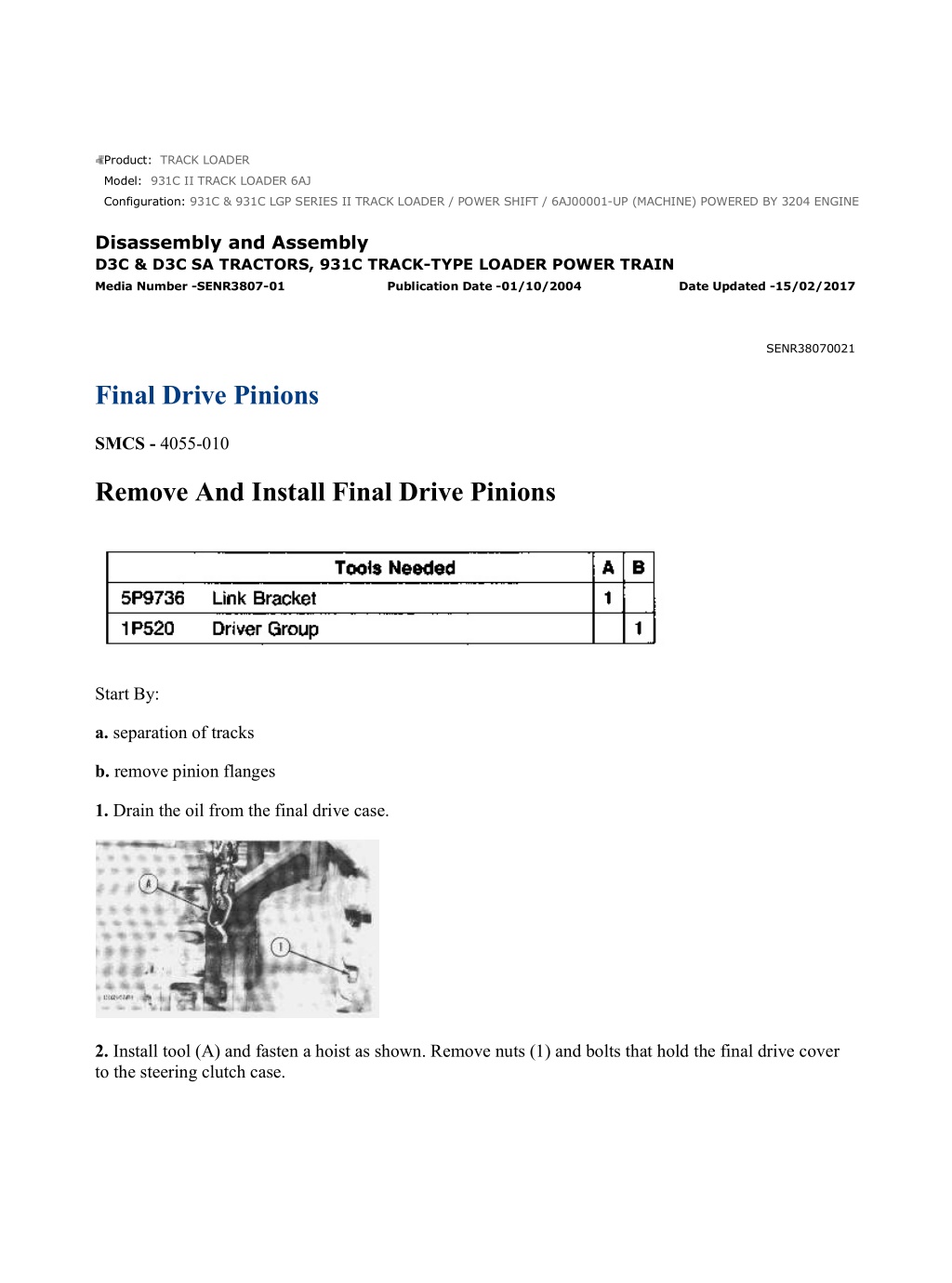
931C & 931C LGP SERIES II TRACK LOADER / POWER SHIFT / 6AJ00001-UP (... 1/4 Product: TRACK LOADER Model: 931C II TRACK LOADER 6AJ Configuration: 931C & 931C LGP SERIES II TRACK LOADER / POWER SHIFT / 6AJ00001-UP (MACHINE) POWERED BY 3204 ENGINE Disassembly and Assembly D3C & D3C SA TRACTORS, 931C TRACK-TYPE LOADER POWER TRAIN Media Number -SENR3807-01 Publication Date -01/10/2004 Date Updated -15/02/2017 SENR38070021 Final Drive Pinions SMCS - 4055-010 Remove And Install Final Drive Pinions Start By: a. separation of tracks b. remove pinion flanges 1. Drain the oil from the final drive case. 2. Install tool (A) and fasten a hoist as shown. Remove nuts (1) and bolts that hold the final drive cover to the steering clutch case. https://127.0.0.1/sisweb/sisweb/techdoc/techdoc_print_page.jsp?returnurl=/sis... 2022/3/14
931C & 931C LGP SERIES II TRACK LOADER / POWER SHIFT / 6AJ00001-UP (... 2/4 Typical Example 3. Install two 3/8" - 16 NC forcing screws (3) in the final drive cover. Tighten the forcing screws evenly and remove final drive (2) and the sprocket hub as a unit. The weight is 158 kg (350 lb.). 4. Remove the race and roller assembly for the pinion shaft from the final drive cover. See the topic, Remove Sprocket Shaft Gear And Cover. 5. Remove pinion (4). 6. Remove bearing races (5) and (6) from pinion (4). 7. Remove nuts (7) that hold bearing cage (8) to the steering clutch case. https://127.0.0.1/sisweb/sisweb/techdoc/techdoc_print_page.jsp?returnurl=/sis... 2022/3/14
931C & 931C LGP SERIES II TRACK LOADER / POWER SHIFT / 6AJ00001-UP (... 3/4 8. Install two 3/8" - 16 NC forcing screws (9). Tighten the forcing screws evenly and remove bearing cage (8). 9. Remove O-ring seal (11) and lip-type seal (10) from bearing cage (8). 10. Remove race and roller assembly (12) from bearing cage (8). NOTE: The following steps are for installation of the final drive pinions. 11. Inspect all parts for damage and make replacements if needed. 12. Lower the temperature of race and roller assembly (12). Install race and roller assembly (12) in bearing cage (8). 13. Use tooling (B) and install the lip-type seal in bearing cage (8) with the lip of the seal toward the final drive cover as shown. Put oil on the lip of the seal. https://127.0.0.1/sisweb/sisweb/techdoc/techdoc_print_page.jsp?returnurl=/sis... 2022/3/14
https://www.ebooklibonline.com Hello dear friend! Thank you very much for reading. Enter the link into your browser. The full manual is available for immediate download. https://www.ebooklibonline.com
931C & 931C LGP SERIES II TRACK LOADER / POWER SHIFT / 6AJ00001-UP (... 4/4 14. Install O-ring seal (11) on the bearing cage. 15. Put bearing cage (8) on the steering clutch case. Install the nuts that hold the bearing cage in place. 16. Heat bearing races (5) and (6) to a maximum temperature of 135 C (275 F). Install bearing races (5) and (6) on pinion (4). 17. Install pinion (4) in the bearing cage. 18. Install the race and roller assembly for the pinion shaft in the final drive cover. See the topic, Install Sprocket Shaft, Gear And Cover. 19. Put 7M7260 Liquid Gasket Material on the machined surfaces of the final drive cover and steering clutch case. 20. Install tool (A) and fasten a hoist to the final drive and sprocket hub. Put the final drive and sprocket hub in position on the steering clutch case. 21. Install nuts (1) and bolts that hold the final drive in place. 22. Fill the final drive with oil to the correct level. See the Operation And Maintenance Manual. End By: a. install pinion flanges b. connection of tracks https://127.0.0.1/sisweb/sisweb/techdoc/techdoc_print_page.jsp?returnurl=/sis... 2022/3/14
931C & 931C LGP SERIES II TRACK LOADER / POWER SHIFT / 6AJ00001-UP (... 1/9 Product: TRACK LOADER Model: 931C II TRACK LOADER 6AJ Configuration: 931C & 931C LGP SERIES II TRACK LOADER / POWER SHIFT / 6AJ00001-UP (MACHINE) POWERED BY 3204 ENGINE Disassembly and Assembly D3C & D3C SA TRACTORS, 931C TRACK-TYPE LOADER POWER TRAIN Media Number -SENR3807-01 Publication Date -01/10/2004 Date Updated -15/02/2017 SENR38070022 Bevel Gear And Pinion SMCS - 3254; 3256-011; 3256-012 Remove Bevel Gear And Pinion Start By: a. remove steering clutch hub couplings b. remove pinion flanges c. remove drive shaft 1. Remove the cover for the bevel gear compartment. 2. Remove nuts (1) from the bolts that hold the bevel gear on the shaft. https://127.0.0.1/sisweb/sisweb/techdoc/techdoc_print_page.jsp?returnurl=/sis... 2022/3/14
931C & 931C LGP SERIES II TRACK LOADER / POWER SHIFT / 6AJ00001-UP (... 2/9 3. Remove the bolts that hold bearing cages (2) on the right and left sides of the bevel gear shaft. Install two3/8 - 16 NC forcing screws in the bearing cages. Tighten the forcing screws evenly and remove bearing cages (2) and shims. Keep the shims with their respective bearing cages for installation. 4. Remove the bolts that hold the pinion bearing cage assembly to the bevel gear case. 5. Install two 3/8" - 16 NC forcing screws in the pinion bearing cage assembly. Tighten the forcing screws evenly and remove pinion bearing cage assembly (3) and shims. Keep the shims with the pinion bearing cage assembly for installation. 7. Move the bevel gear shaft away from the bevel gear. 8. Remove bevel gear (5) and bevel gear shaft (4). 9. Remove the bearing cups, O-ring seals and lip-type seals from the two bevel gear bearing cages. 10. Remove the bearing cones from the bevel gear shaft with tooling (A). https://127.0.0.1/sisweb/sisweb/techdoc/techdoc_print_page.jsp?returnurl=/sis... 2022/3/14
931C & 931C LGP SERIES II TRACK LOADER / POWER SHIFT / 6AJ00001-UP (... 3/9 Typical Example 11. Remove bolts (7) that hold the retainer on the pinion shaft flange (6). NOTE: Keep the shims with the retainer for correct installation. Typical Example 12. Remove pinion bearing cage (8) from the pinion with tooling (A). NOTE: Keep the puller attachment away from the inner bearing cone when tooling (A) is installed. Typical Example 13. Remove the O-ring seal and lip-type seal from pinion bearing cage (8). 14. Remove the bearing cups from pinion bearing cage (8). 15. Remove inner bearing cone (9) from pinion shaft (10) with tooling (A). Install Bevel Gear And Pinion https://127.0.0.1/sisweb/sisweb/techdoc/techdoc_print_page.jsp?returnurl=/sis... 2022/3/14
931C & 931C LGP SERIES II TRACK LOADER / POWER SHIFT / 6AJ00001-UP (... 4/9 1. Lower the temperature of bearing cups (11). Install bearing cups (11) in the pinion bearing cage. 2. Lower the temperature of bearing cups (12). Install bearing cups (12) in bevel gear bearing cages (2). 3. Heat bearing cone (9) to a maximum temperature of 135 C (275 F). Install bearing cone (9) on the pinion shaft. Install the pinion shaft in pinion bearing cage (8). Install bearing cone (13) on the pinion shaft. Install O-ring seal (14). Install the lip-type seal in the pinion bearing cage with the lip of the seal toward the oil that is to be sealed. 4. Install the flange, retainer and bolts. Tighten the bolts which will pull the bearing cone on to the pinion shaft. Turn the pinion shaft while the bolts are tightened until a small preload is felt. 5. Install tooling (B) as shown and check the end play in the pinion shaft. Add enough shims behind the retainer to get 0 to 0.05 mm (0 to .002 in.) end play in the pinion shaft. Install the O-ring, retainer, lock and bolts. https://127.0.0.1/sisweb/sisweb/techdoc/techdoc_print_page.jsp?returnurl=/sis... 2022/3/14
931C & 931C LGP SERIES II TRACK LOADER / POWER SHIFT / 6AJ00001-UP (... 5/9 6. Heat bearing cones (15) to a maximum temperature of 135 C (275 F). Install bearing cones (15) on the bevel gear shaft. 7. Put the bevel gear into position in the bevel gear case. 8. Install the bevel gear shaft through the bevel gear. 9. Install the O-ring seal and lip-type seal (17) in the left bearing cage. The spring loaded lip of the lip- type seal must be toward the bevel gear. 10. Install the left bearing cage with original amount of shims (16) behind the bearing cage. 11. Put bevel gear shaft (4) into position in bevel gear (5). Install the bolts and nuts that hold the bevel gear to the bevel gear shaft. 12. Install the O-ring seal and lip-type seal (19) in the righ bearing cage. The spring loaded lip of the lip- type seal must be toward the bevel gear. https://127.0.0.1/sisweb/sisweb/techdoc/techdoc_print_page.jsp?returnurl=/sis... 2022/3/14
931C & 931C LGP SERIES II TRACK LOADER / POWER SHIFT / 6AJ00001-UP (... 6/9 13. Install two 1/2"- 13 NC guide bolts (18). Install the right bearing cage on the shaft without shims. Install the bolts and tighten the bolts evenly, while the bevel gear shaft is turned, until a small amount of bearing preload is felt. 14. Tighten nuts (1) on the bevel gear to a torque of 142 14 N m (106 10 lb.ft.). 15. Install tooling (B) on the end of the bevel gear shaft. Loosen the bolts around the right bearing cage evenly until there is no end play or preload on the bevel gear shaft. 16. Make a measurement of the clearance between the right bearing cage and the bevel gear case with a feeler gauge. The clearance must be the same at all bolt locations. 17. Remove tooling (B) and the right bearing cage. Install shims equal to the thickness measured minus 0.18 mm (.007 in.). Install the right bearing cage. 18. Check the amount of torque needed to turn the bevel gear shaft constantly for two or three turns. The torque must be 3.9 to 5.6 N m (35 to 50 lb.in.). Add or remove shims as necessary if the torque is not correct. 19. Slide pinion bearing cage assembly (3), with the large oil hole in the bearing cage up, into the bevel gear case. 20. Install original shims (20) behind the pinion bearing cage. If the original shims are not available, install enough shims behind the pinion bearing cage to get the heel of the bevel gear in alignment with the pinion gear. https://127.0.0.1/sisweb/sisweb/techdoc/techdoc_print_page.jsp?returnurl=/sis... 2022/3/14
931C & 931C LGP SERIES II TRACK LOADER / POWER SHIFT / 6AJ00001-UP (... 7/9 21. Install tooling (B) to check the gear clearance (backlash) between the bevel gear and pinion. Turn the gears and check the gear clearance (backlash) at several places to find out the place where there is the least amount of gear clearance (backlash). The correct gear clearance (backlash) for a power shift machine is 0.20 + 0.10 or - .08 mm (.008 + .004 or - .003 in.). The correct gear clearance (backlash) for a direct drive machine is 0.25 + 0.10 or - 0.8 mm (.010 + .004 or - .003 in.). 22. The gear clearance (backlash) can be increased, or decreased by removal of shims from one bearing cage and installation behind the other. 23. Preload on the bearings of the bevel gear shaft will not be changed if shims are moved from one side to the other and the thickness of the shims is kept the same. 24. After the gear clearance (backlash) and bearing preload adjustments have been made, check the tooth contact between the bevel gear and pinion as follows: a. Put Prussian blue, red lead or paint with a brush on the bevel gear teeth. Turn the pinion and check the contact area of the teeth on the drive side of the bevel gear. When the tooth contact on the drive side is correct, reverse side must also be correct. Correct Tooth Contact Setting b. With no load, the correct tooth setting will be as shown. The area of contact starts near the toe of the gear and goes about 30% up the length of the tooth with this setting. When a load is put on the gear, it will be over the correct area of the teeth. https://127.0.0.1/sisweb/sisweb/techdoc/techdoc_print_page.jsp?returnurl=/sis... 2022/3/14
931C & 931C LGP SERIES II TRACK LOADER / POWER SHIFT / 6AJ00001-UP (... 8/9 Short Toe Contact Setting c. If the bevel pinion shaft is too far away from the bevel gear, short toe contact will be the result as shown. The teeth of the pinion will be in contact with toe end of convex faces (part that makes a curve toward the outside) and top edge of heel end of concave faces (part that makes a curve toward inside). To correct this, move the pinion shaft closer to the bevel gear. To do this, remove shims between pinion bearing cage and bevel gear case. Check gear clearance (backlash) and tooth contact again. Short Heel Contact Setting d. If the pinion shaft is too near to the center of the bevel gear, short heel contact will be the result as shown. The teeth of the pinion shaft will be in contact with the toe ends of concave faces (part that makes a curve toward the inside) and the heel end of convex faces (part that makes a curve toward the outside). To correct this, move the pinion shaft away from the bevel gear. To do this, add shims between pinion bearing cage and bevel gear case. Check gear clearance (backlash) and tooth contact again. NOTE: Several adjustments must be made for the correct tooth contact setting. If the gear clearance (backlash) is changed, the tooth contact setting will change. https://127.0.0.1/sisweb/sisweb/techdoc/techdoc_print_page.jsp?returnurl=/sis... 2022/3/14
931C & 931C LGP SERIES II TRACK LOADER / POWER SHIFT / 6AJ00001-UP (... 9/9 e. Remove all of the Prussian blue, red lead or paint from the bevel gear and pinion. End By a. install drive shaft b. install pinion flanges c. install steering clutch hub couplings https://127.0.0.1/sisweb/sisweb/techdoc/techdoc_print_page.jsp?returnurl=/sis... 2022/3/14
931C & 931C LGP SERIES II TRACK LOADER / POWER SHIFT / 6AJ00001-UP (... 1/8 Product: TRACK LOADER Model: 931C II TRACK LOADER 6AJ Configuration: 931C & 931C LGP SERIES II TRACK LOADER / POWER SHIFT / 6AJ00001-UP (MACHINE) POWERED BY 3204 ENGINE Disassembly and Assembly D3C & D3C SA TRACTORS, 931C TRACK-TYPE LOADER POWER TRAIN Media Number -SENR3807-01 Publication Date -01/10/2004 Date Updated -15/02/2017 SENR38070023 Engine And Transmission (3F/1R Power Shift) SMCS - 1004-010; 1004-029 Remove And Install Engine And Transmission (3F/1R Power Shift) Start By: a. remove radiator and guard* b. remove air cleaner group* c. remove muffler* d. remove drive shaft *These operations are in the disassembly and Assembly Module, 3204 Vehicular Engine Supplement For D3C, D3C SA And 931C, Form No. SENR3803. NOTE: This operation is done on a 931C with a 3F/1R power shift transmission and a ROPS. 1. Drain the oil from the hydraulic tank. 2. Turn the valve on the bottom of the fuel tank to the "OFF" position. https://127.0.0.1/sisweb/sisweb/techdoc/techdoc_print_page.jsp?returnurl=/sis... 2022/3/14
931C & 931C LGP SERIES II TRACK LOADER / POWER SHIFT / 6AJ00001-UP (... 2/8 3. Disconnect wire harness (1) at the firewall. Remove bolts (4) that hold clips (2) in place. 4. Disconnect oil pressure gauge oil line (3) from the fitting in the cylinder block. 5. Disconnect air cleaner indicator line (5) from the fitting in the air inlet manifold. 6. Disconnect water temperature sensing unit (6). Remove clips (7) that hold the water temperature sensing line in place. 7. Disconnect wire (8) for the lights. Disconnect battery cable (9) from the starting motor. https://127.0.0.1/sisweb/sisweb/techdoc/techdoc_print_page.jsp?returnurl=/sis... 2022/3/14
931C & 931C LGP SERIES II TRACK LOADER / POWER SHIFT / 6AJ00001-UP (... 3/8 8. Disconnect oil line (10) from oil line (12). Remove bolt (11) that holds the clips to the bracket. 9. Disconnect wire (13) for the bucket positioner kickout. 10. Disconnect governor linkage (15) from the governor lever. Disconnect fuel supply line (14). Put plugs in the openings. 11. Loosen nut (16) and remove the governor linkage from the bracket. 12. Disconnect oil line (17) from oil line (18). 13. Remove the floor plates from the cab or the operator's platform. 14. Disconnect transmission control linkage (19) from the lever on the transmission. 15. Disconnect wire harness (20). Disconnect wires (22) for the back-up warning alarm. 16. Disconnect oil line (23) from the transmission. https://127.0.0.1/sisweb/sisweb/techdoc/techdoc_print_page.jsp?returnurl=/sis... 2022/3/14
931C & 931C LGP SERIES II TRACK LOADER / POWER SHIFT / 6AJ00001-UP (... 4/8 17. Remove clamps (21) that hold the battery cable to the transmission. 18. Remove bolt (25) and nut that hold clip (24) to bracket (26). 19. Disconnect oil line (27) from the steering clutch control valve. 20. Disconnect torque converter oil temperature sensing unit (29) from the transmission. 21. Remove transmission oil filler tube (30) from the transmission. 22. Remove the bolt that holds the clamp for the torque converter oil cooler lines (28) and the ground strap to the left side of the frame. 23. Remove the head bolt and install tool (A) on the right rear of the cylinder head. Fasten a hoist to the rear lifting bracket and tool (A). 24. Fasten tool (B) to the front lifting bracket. https://127.0.0.1/sisweb/sisweb/techdoc/techdoc_print_page.jsp?returnurl=/sis... 2022/3/14
931C & 931C LGP SERIES II TRACK LOADER / POWER SHIFT / 6AJ00001-UP (... 5/8 25. Put a hydraulic floor jack under the transmission. 26. Remove bolt (31), sleeve and mount assembly (32) from each side of the rear transmission support group. 27. Lift the transmission with the hydraulic floor jack and remove rear support assembly (33) from each side of the transmission. 28. Remove bolt (36) that holds clamp (37) to the frame. 29. Remove a bolt (34), sleeve and mount assembly (35) from each side of the engine front support group. 30. Fasten a hoist to the crosstube of the loader frame as shown. Remove the support bracket. See the topic, Install And Remove Support Bracket (931C). Lower the bucket to the ground. NOTE: Make a final check to be sure all removals and disconnections have been made from the engine and transmission. https://127.0.0.1/sisweb/sisweb/techdoc/techdoc_print_page.jsp?returnurl=/sis... 2022/3/14
931C & 931C LGP SERIES II TRACK LOADER / POWER SHIFT / 6AJ00001-UP (... 6/8 31. Remove engine (38) and the transmission from the machine. The weight of the engine and transmission is 720 kg (1600 lb.). NOTE: The following steps are for installation of the engine and transmission. 32. Install tool (A) on the right rear of the cylinder head. Fasten a hoist to the rear lifting bracket and tool (A). Install tool (B) on the front lifting bracket and fasten it to the hoist. Put the transmission and engine (38) in position in the machine. 33. Install bolt (36) that holds clamp (37) for the torque converter oil cooler lines in place. 34. Install mount assembly (35), the sleeve and bolt (34) on each side for the front engine support group. Tighten the bolts to a torque of 360 47 N m (265 35 lb.ft.). 35. Put a hydraulic floor jack in place under the transmission. Lift the transmission and install rear support assembly (33) on each side of the transmission. Install the bolts that hold the support assemblies to the transmission. Tighten the bolts to a torque of 120 14 N m (90 10 lb.ft.). 36. Install mount assembly (32), the sleeve and bolt (31) on each side for the rear transmission support group. Tighten the bolts to a torque of 360 47 N m (265 35 lb.ft.). 37. Remove the hydraulic floor jack and hoist. Remove tool (B). Remove tool (A). Put 5P3931 Anti- Seize Compound on the threads of the head bolt. Tighten the head bolt to a torque of 150 7 N m (110 5 lb.ft.). 38. Fasten a hoist to the crosstube of the loader frame as shown. Install the support bracket. See the topic, Install And Remove Support Bracket (931C). 39. Install the bolt that holds the ground strap and clamp for torque converter oil cooler lines (28) to the left side of the frame. 40. Connect torque converter oil temperature sensing unit (29) to the transmission case. Install transmission oil filler tube (30). 41. Install bolt (25) and nut that holds clamp (24) for the transmission oil filler tube to bracket (26). 42. Connect oil line (27) to the steering clutch control valve. 43. Install clamps (21) that hold the battery cable to the transmission. 44. Connect wire harness (20). Connect wires (22) for the back-up warning alarm. 45. Connect transmission control linkage (19) to the lever on the transmission. 46. Connect oil line (23) to the transmission. Install the floor plates. 47. Install governor linkage (15) in the bracket. Tighten nut (16). 48. Connect oil line (17) to oil line (18). 49. Remove the plugs and install fuel supply line (14). 50. Connect governor linkage (15) to the lever of the governor. 51. Connect wire (13) for the bucket positioner kickout. 52. Connect oil line (12) to oil line (10). 53. Install bolt (11) that holds the clamps to the bracket. https://127.0.0.1/sisweb/sisweb/techdoc/techdoc_print_page.jsp?returnurl=/sis... 2022/3/14
931C & 931C LGP SERIES II TRACK LOADER / POWER SHIFT / 6AJ00001-UP (... 7/8 54. Connect wire (8) for the lights. 55. Connect battery cable (9) to the starting motor. 56. Connect air cleaner indicator line (5) to the fitting in the air inlet manifold. 57. Install clips (7) that hold the water temperature sensing line in place. Connect water temperature sensing unit (6). 58. Connect oil pressure gauge oil line (3) to the fitting in the cylinder block. 59. Put clips (2) that hold wire harness (1) in place and install bolts (4). Connect wire harness (1) at the firewall. 60. Fill the hydraulic tank with oil to the correct level. See the Operation And Maintenance Manual. 61. Turn the valve on the bottom of the fuel tank to the "ON" position. End By: a. install drive shaft b. install muffler* c. install air cleaner group* d. install radiator and guard* *These operations are in the Disassemble And Assemble Module, 3204 Vehicular Engine Supplement For D3C, D3C SA And 931C, Form No. SENR3803. Separation And Connection Of Engine And Transmission (3F/1R Power Shift) Start By: a. remove engine and transmission 1. Remove back-up warning alarm (1) from the transmission. https://127.0.0.1/sisweb/sisweb/techdoc/techdoc_print_page.jsp?returnurl=/sis... 2022/3/14
931C & 931C LGP SERIES II TRACK LOADER / POWER SHIFT / 6AJ00001-UP (... 8/8 2. Disconnect wires (6). Remove clip (2), and push wire harness (3) clear of the transmission. 3. Remove oil line (4) and ground strap (5) from the transmission. 4. Remove torque converter oil cooler lines (7) from the transmission case. 5. Install a 5/16"-18 NC forged eyebolt (9) in the transmission. Install tooling (A) on the transmission. Fasten a hoist to tooling (A). Fasten tooling (B) to eyebolt (9) and the hoist. 6. Remove bolts (10) that hold the transmission to the flywheel housing. Remove transmission (8). The weight of the transmission is 203 Kg (450 lb.). NOTE: The following steps are for connection of the engine and transmission. 7. Inspect the O-ring seal on the front of the transmission case for damage and make a replacement if needed. 8. Install a 5/16" - 18 NC forged eyebolt (9) in the transmission. Install tooling (A) on the transmission. Fasten a hoist to tooling (A). Fasten tooling (B) to eyebolt (9) and the hoist. 9. Make sure the internal teeth of the flywheel are in correct engagement with the external teeth on the torque converter, and install transmission (8) against the flywheel housing. 10. Install bolts (10) that hold the transmission to the flywheel housing. 11. Install torque converter oil cooler lines (7) on the transmission case. 12. Install oil line (4) and ground strap (5). 13. Put wire harness (3) in position, and connect wires (6). Install clip (2). 14. Install back-up warning alarm (1) on the transmission. End By: a. install engine and transmission https://127.0.0.1/sisweb/sisweb/techdoc/techdoc_print_page.jsp?returnurl=/sis... 2022/3/14
931C & 931C LGP SERIES II TRACK LOADER / POWER SHIFT / 6AJ00001-UP (... 1/2 Product: TRACK LOADER Model: 931C II TRACK LOADER 6AJ Configuration: 931C & 931C LGP SERIES II TRACK LOADER / POWER SHIFT / 6AJ00001-UP (MACHINE) POWERED BY 3204 ENGINE Disassembly and Assembly D3C & D3C SA TRACTORS, 931C TRACK-TYPE LOADER POWER TRAIN Media Number -SENR3807-01 Publication Date -01/10/2004 Date Updated -15/02/2017 SENR38070024 Transmission Oil Pump And Transmission Hydraulic Control Valve (3F/1R Power Shift) SMCS - 3152-010; 3153 Remove And Install Transmission Oil Pump And Transmission Hydraulic Control Valve (3F/1R Power Shift) Start By: a. remove engine and transmission NOTE: It is not necessary to make a separation of the transmission from the engine. 1. Remove cover (1) from the transmission. 2. Remove cover (2) from the oil filter. Remove the oil filter. 3. Remove suction tube (4) for the oil pump through the opening for the oil filter. https://127.0.0.1/sisweb/sisweb/techdoc/techdoc_print_page.jsp?returnurl=/sis... 2022/3/14
Suggest: For more complete manuals. Please go to the home page. https://www.ebooklibonline.com If the above button click is invalid. Please download this document first, and then click the above link to download the complete manual. Thank you so much for reading
931C & 931C LGP SERIES II TRACK LOADER / POWER SHIFT / 6AJ00001-UP (... 2/2 4. Remove clip (5) from the oil tube. Push the oil tube away from the control valve body. 5. Remove four bolts (6) that hold the control valve on the transmission oil manifold. 6. Remove oil pump (7) and control valve (3) as a unit from the transmission. 7. Remove three bolts (8) that hold oil pump (7) to control valve (3). Remove oil pump (7). 8. Remove relief valve (9) from the transmission oil manifold. NOTE: The following steps are for installation of the transmission oil pump and transmission hydraulic control valves. 9. Install relief valve (9) in the transmission oil manifold. 10. Put oil pump (7) in position on control valve (3), and install three bolts (8) that hold them together. Tighten the bolts to a torque of 35 4 N m (25 3 lb.ft.). 11. Position oil pump (7) and control valve (3) as a unit on the transmission oil manifold, and install four bolts (6). Tighten the bolts to a torque of 30 4 N m (22 3 lb.ft.). NOTE: Be sure the shifting lever is connected to the selector valve spool when the control valve is installed. 12. Slide the oil tube into the control valve, and install clip (5). 13. Install suction tube (4) for the oil pump. 14. Install the oil filter. 15. Install covers (1) and (2). End By: https://127.0.0.1/sisweb/sisweb/techdoc/techdoc_print_page.jsp?returnurl=/sis... 2022/3/14
931C & 931C LGP SERIES II TRACK LOADER / POWER SHIFT / 6AJ00001-UP (... 1/2 Product: TRACK LOADER Model: 931C II TRACK LOADER 6AJ Configuration: 931C & 931C LGP SERIES II TRACK LOADER / POWER SHIFT / 6AJ00001-UP (MACHINE) POWERED BY 3204 ENGINE Disassembly and Assembly D3C & D3C SA TRACTORS, 931C TRACK-TYPE LOADER POWER TRAIN Media Number -SENR3807-01 Publication Date -01/10/2004 Date Updated -15/02/2017 SENR38070025 Transmission Oil Pump (3F/1R Power Shift) SMCS - 3153-017 Disassemble And Assemble Transmission Oil Pump (3F/1R Power Shift) Start By: a. remove transmission oil pump and transmission hydraulic control valve 1. Remove drive gear (1) from the oil pump with tooling (A). https://127.0.0.1/sisweb/sisweb/techdoc/techdoc_print_page.jsp?returnurl=/sis... 2022/3/14
https://www.ebooklibonline.com Hello dear friend! Thank you very much for reading. Enter the link into your browser. The full manual is available for immediate download. https://www.ebooklibonline.com