Caterpillar Cat 931 LGP TRACK LOADER (Prefix 10N) Service Repair Manual Instant Download (10N00001-00525)
Please open the website below to get the complete manualnn//

Download Presentation

Please find below an Image/Link to download the presentation.
The content on the website is provided AS IS for your information and personal use only. It may not be sold, licensed, or shared on other websites without obtaining consent from the author. Download presentation by click this link. If you encounter any issues during the download, it is possible that the publisher has removed the file from their server.
E N D
Presentation Transcript
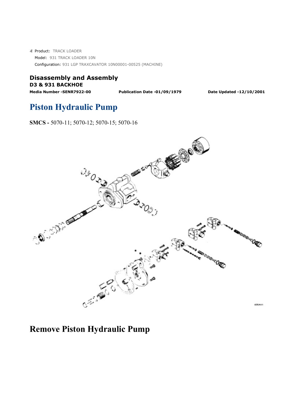
931 LGP TRAXCAVATOR 10N00001-00525 (MACHINE)(UEG0750S - 00) - Docu... 1/18 Product: TRACK LOADER Model: 931 TRACK LOADER 10N Configuration: 931 LGP TRAXCAVATOR 10N00001-00525 (MACHINE) Disassembly and Assembly D3 & 931 BACKHOE Media Number -SENR7922-00 Publication Date -01/09/1979 Date Updated -12/10/2001 Piston Hydraulic Pump SMCS - 5070-11; 5070-12; 5070-15; 5070-16 Remove Piston Hydraulic Pump https://127.0.0.1/sisweb/sisweb/techdoc/techdoc_print_page.jsp?returnurl=/sis... 2022/4/27
931 LGP TRAXCAVATOR 10N00001-00525 (MACHINE)(UEG0750S - 00) - Docu... 2/18 1. Drain the oil from the hydraulic tank. NOTE: Steps 2 through 6 are for the D3B only. 2. Remove the cotter pin that holds cable (1) to lever (3) for the check valve. Remove the pin to disconnect the cable from the lever. 3. Loosen nut (2) and remove the cable from support (4). 4. Disconnect pump oil line (5) from connector (6). Remove connector (6) from tee fitting (7). 5. Loosen clamps (8) that hold supply oil hose (9) in place. Slide the hose away from supply oil tube assembly (10). Remove supply oil tube assembly (10) from the piston hydraulic pump. https://127.0.0.1/sisweb/sisweb/techdoc/techdoc_print_page.jsp?returnurl=/sis... 2022/4/27
931 LGP TRAXCAVATOR 10N00001-00525 (MACHINE)(UEG0750S - 00) - Docu... 3/18 6. Disconnect sensor oil line (11) from the servo valve and the tee fitting and remove it. NOTE: Step 7 is for the 931B only. 7. Disconnect the pump oil line and supply oil line at the piston hydraulic pump. 8. Disconnect drain oil line (12) from the bottom of the piston hydraulic pump. NOTE: Step 9 is for the D3B only. 9. Remove the bolt that holds bracket (15) to the inlet manifold. 10. Remove two bolts (13) and nuts that hold the piston hydraulic pump to the timing gear plate. Remove piston hydraulic pump (14) from the timing gear plate. NOTE: Step 11 is for the D3B only. 11. Remove check valve (16) and tee fitting (17) from piston hydraulic pump (14). https://127.0.0.1/sisweb/sisweb/techdoc/techdoc_print_page.jsp?returnurl=/sis... 2022/4/27
https://www.ebooklibonline.com Hello dear friend! Thank you very much for reading. Enter the link into your browser. The full manual is available for immediate download. https://www.ebooklibonline.com
931 LGP TRAXCAVATOR 10N00001-00525 (MACHINE)(UEG0750S - 00) - Docu... 4/18 12. Remove nut (18) and lock (19). NOTICE Do not remove gear (20) with tooling (A) unless nut (18) is installed. 13. Install nut (18) until it is even with the end of the shaft. Use tooling (A) and loosen gear (20) from the taper on the shaft. Remove tooling (A) and gear (20). Install Piston Hydraulic Pump 1. Put gear (1) in position on the shaft of the piston hydraulic pump. https://127.0.0.1/sisweb/sisweb/techdoc/techdoc_print_page.jsp?returnurl=/sis... 2022/4/27
931 LGP TRAXCAVATOR 10N00001-00525 (MACHINE)(UEG0750S - 00) - Docu... 5/18 2. Install lock (2) and nut (3) that holds the gear to the shaft. Tighten the nut to a torque of 50 5 lb.ft. (70 7 N m). NOTE: Step 3 is for the D3B only. 3. Install check valve (5) and tee fitting (6) on piston hydraulic pump (4). 4. Make sure the gasket is in place and install piston hydraulic pump (4) against the timing gear cover. Install the two bolts and nuts that hold it in place. NOTE: Step 5 is for the D3B only. 5. Install the bolt that holds bracket (7) to the inlet manifold. NOTE: Step 6 is for the 931B only. 6. Connect the pump oil line and supply oil line to the piston hydraulic pump. 7. Connect drain oil line (8) to the bottom of the piston hydraulic pump. NOTE: Steps 8 through 13 are for the D3B only. https://127.0.0.1/sisweb/sisweb/techdoc/techdoc_print_page.jsp?returnurl=/sis... 2022/4/27
931 LGP TRAXCAVATOR 10N00001-00525 (MACHINE)(UEG0750S - 00) - Docu... 6/18 8. Connect sensor oil line (9) to the tee fitting and to the servo valve. 9. Install supply oil tube assembly (10) to the piston hydraulic pump. 10. Slide supply oil hose (12) on to the supply oil tube assembly. Install clamps (13). 11. Install connector (11) in the tee fitting. Connect pump oil line (14) to connector (11). 12. Put cable (15) in place in support (18) and tighten nut (16). 13. Install pin (17) to connect the cable to the lever for the check valve. Install the cotter pin that holds the pin in place. 14. Fill the hydraulic tank to the correct level. See LUBRICATION AND MAINTENANCE GUIDE. https://127.0.0.1/sisweb/sisweb/techdoc/techdoc_print_page.jsp?returnurl=/sis... 2022/4/27
931 LGP TRAXCAVATOR 10N00001-00525 (MACHINE)(UEG0750S - 00) - Docu... 7/18 Disassemble Piston Hydraulic Pump start by: a) remove piston hydraulic pump 1. Check the direction of arrows (1) and (2). The direction of the arrows must be in the same direction. This is the rotation of the piston hydraulic pump. 2. Remove servo valve (3) and gasket from the pump. Remove the O-ring seal from the servo valve. 3. Disassemble the pressure compensator valve spool assembly from the servo valve housing as follows: There is spring force behind cap (4). https://127.0.0.1/sisweb/sisweb/techdoc/techdoc_print_page.jsp?returnurl=/sis... 2022/4/27
931 LGP TRAXCAVATOR 10N00001-00525 (MACHINE)(UEG0750S - 00) - Docu... 8/18 a) Remove cap (4) from the servo valve housing. Remove the O-ring seal from the cap. b) Remove stop (9), shims (8), spring (7), retainer (6) and pressure compensator valve spool (5) from the servo valve housing. NOTE: The 931B does not have a flow compensator valve spool assembly in the servo valve. Step 4 is for the D3B only. 4. Disassemble the flow compensator valve spool assembly from the servo valve housing as follows: D3B ONLY a) Remove fitting (10) from the servo valve housing. D3B ONLY b) Remove shims (14), stop (13), spring (12) and flow compensator valve spool (11) from the servo valve housing. https://127.0.0.1/sisweb/sisweb/techdoc/techdoc_print_page.jsp?returnurl=/sis... 2022/4/27
931 LGP TRAXCAVATOR 10N00001-00525 (MACHINE)(UEG0750S - 00) - Docu... 9/18 5. Remove four bolts (15) and remove plate assembly (16) and gasket from the pump housing. 6. Remove piston (18) from the plate assembly. 7. If necessary, remove bearing (17) from the plate assembly. NOTICE Be extra careful not to cause damage to the machined (highly finished) surface on the plate assembly and barrel assembly. 8. Remove barrel assembly (19). 9. Put identification on the pistons and by the openings in the barrel so the pistons will be installed in their original cylinders. 10. Remove pistons (22) from barrel (23). 11. Remove retraction plate (21) and pivot (20) from barrel (23). There is spring force behind snap ring (29). https://127.0.0.1/sisweb/sisweb/techdoc/techdoc_print_page.jsp?returnurl=/sis... 2022/4/27
931 LGP TRAXCAVATOR 10N00001-00525 (MACHINE)(UEG0750S - 00) - Do... 10/18 12. Use a press and tooling (B) to put spring (27) in compression. Use tooling (A) to remove snap ring (29). Slowly remove the force from the spring. 13. Remove spacer (28), spring (27), spacer (26), pins (25) and pin keeper (24) from barrel (23). 14. Remove snap ring (30) from the pump housing with tool (A). 15. Use a soft hammer to remove shaft (31) from the pump housing. Remove the seal and washer with the shaft. 16. Remove snap ring (35) from shaft (31) with tool (C). Remove bearing race (34), bearing (36) and bearing race (33) from shaft (31). Remove snap ring (32) with tool (C). https://127.0.0.1/sisweb/sisweb/techdoc/techdoc_print_page.jsp?returnurl=/sis... 2022/4/27
931 LGP TRAXCAVATOR 10N00001-00525 (MACHINE)(UEG0750S - 00) - Do... 11/18 17. Remove snap rings (37) and (39) from each side of the pump housing with tool (A). 18. Remove covers (38) and (40) from each side of the pump housing. Remove the O-ring seals from each side of the pump housing. 19. Remove races (42) and bearings (41) from each side of the pump housing. 20. Remove swashplate (43) from the pump housing. 21. Remove spring pin (44) and button (45) from swashplate (43). https://127.0.0.1/sisweb/sisweb/techdoc/techdoc_print_page.jsp?returnurl=/sis... 2022/4/27
931 LGP TRAXCAVATOR 10N00001-00525 (MACHINE)(UEG0750S - 00) - Do... 12/18 22. Remove spring guide (48) and spring (47) from the pump housing. 23. Use tooling (B) and remove bearing (46) from the pump housing. Assemble Piston Hydraulic Pump NOTE: See GUIDELINE FOR REUSABLE PARTS, PISTON PUMPS AND MOTORS, Form No. SEBF8032. 1. Make sure all of the parts of the piston hydraulic pump are clean. Put clean oil on all of the parts of the piston hydraulic pump. Inspect all O-ring seals for damage and make replacements if needed. 2. Install the bearing in the pump housing with tooling (A). The bearing must be installed with the end that has numbers on it toward the outside of the pump and .078 in. (1.98 mm) below the seat of the counterbore. https://127.0.0.1/sisweb/sisweb/techdoc/techdoc_print_page.jsp?returnurl=/sis... 2022/4/27
931 LGP TRAXCAVATOR 10N00001-00525 (MACHINE)(UEG0750S - 00) - Do... 13/18 3. Put spring (1) and spring guide (2) in position in the pump housing. 4. Put button (5) in position on swashplate (3). Install spring pin (4) that holds the button in place with a punch and hammer. 5. Put swashplate (3) in position in the pump housing. 6. Install bearings (6) and races (7) in each side of the pump housing. https://127.0.0.1/sisweb/sisweb/techdoc/techdoc_print_page.jsp?returnurl=/sis... 2022/4/27
931 LGP TRAXCAVATOR 10N00001-00525 (MACHINE)(UEG0750S - 00) - Do... 14/18 7. Put O-ring seals (8) and covers (9) in position on each side of the pump housing. 8. Install snap ring (10) with tool (B) in each side of the pump housing. 9. Use tool (C) and install snap ring (12) on shaft (11). 10. Put race (13), bearing (16) and race (14) in position on shaft (11). 11. Use tool (C) and install snap ring (15) on shaft (11). 12. Put shaft (11) in position in the pump housing. 13. Install washer (17) and seal (18) in the pump housing. The lip of the seal must be installed toward the inside of the pump housing. https://127.0.0.1/sisweb/sisweb/techdoc/techdoc_print_page.jsp?returnurl=/sis... 2022/4/27
931 LGP TRAXCAVATOR 10N00001-00525 (MACHINE)(UEG0750S - 00) - Do... 15/18 14. Install snap ring (19) in the pump housing with tool (B). NOTICE Be extra careful not to cause damage to the machined (highly finished) surfaces of the barrel assembly. 15. Put pin keeper (20) in compression and install it in the splines of barrel (26). NOTICE Pins (21) must be installed in the special grooves in the barrel. 16. Install three pins (21) with the head ends toward the inside of the barrel. 17. Install spacers (22), spring (23) and spacer (24) in barrel (26). 18. Use a press and tooling (A) to put spring (23) in compression. Install snap ring (25) in barrel (26) with tooling (B). https://127.0.0.1/sisweb/sisweb/techdoc/techdoc_print_page.jsp?returnurl=/sis... 2022/4/27
931 LGP TRAXCAVATOR 10N00001-00525 (MACHINE)(UEG0750S - 00) - Do... 16/18 19. Install pivot (27) and retraction plate (29) on the barrel. 20. Install pistons (28) in their original cylinders in barrel (26). 21. Install barrel assembly (30) on the shaft. Make sure the piston slippers are in contact with the swashplate. NOTICE Be extra careful not to cause damage to the machined (highly polished) surface of the plate assembly. 22. Install piston (31) on plate assembly (32). 23. Install the bearing in plate assembly (32) with tooling (A). The bearing must be installed with the end with numbers on it toward the inside of the pump and .03 in. (0.76 mm) below the surface of the plate assembly. 24. Install gasket (33) and plate assembly (32) on the pump housing. Install the bolts that hold the plate assembly to the pump housing. Tighten the bolts to a torque of 29 2 lb.ft. (40 3 N m). NOTE: The 931B does not have a flow compensator valve spool assembly in the servo valve. Step 25 is for the D3B only. https://127.0.0.1/sisweb/sisweb/techdoc/techdoc_print_page.jsp?returnurl=/sis... 2022/4/27
931 LGP TRAXCAVATOR 10N00001-00525 (MACHINE)(UEG0750S - 00) - Do... 17/18 D3B ONLY 25. Assemble the flow compensator valve spool assembly as follows: a) Install flow compensator valve spool (34), spring (35), stop (36) and shims (37) in the servo valve housing. b) Install O-ring seal (38) and fitting (39) in the servo valve housing. 26. Assemble the pressure compensator valve spool assembly as follows: a) Install pressure compensator valve spool (40), retainer (41), spring (42), shims (43) and stop (44) in the servo valve housing. b) Install O-ring seal (45) and cap (46) in the servo valve housing. NOTE: Make sure the arrows on the plate assembly and the servo valve are in the same direction of pump rotation. https://127.0.0.1/sisweb/sisweb/techdoc/techdoc_print_page.jsp?returnurl=/sis... 2022/4/27
931 LGP TRAXCAVATOR 10N00001-00525 (MACHINE)(UEG0750S - 00) - Do... 18/18 27. Make sure gasket (47) and the O-ring seal is in the correct position. Install servo valve (48) on the pump. Tighten the bolts to a torque of 11 1 lb.ft. (15 1 N m). end by: a) install piston hydraulic pump https://127.0.0.1/sisweb/sisweb/techdoc/techdoc_print_page.jsp?returnurl=/sis... 2022/4/27
931 LGP TRAXCAVATOR 10N00001-00525 (MACHINE)(UEG0750S - 00) - Docu... 1/2 Product: TRACK LOADER Model: 931 TRACK LOADER 10N Configuration: 931 LGP TRAXCAVATOR 10N00001-00525 (MACHINE) Disassembly and Assembly 3204 VEHICULAR ENGINE FOR D3 TRACTOR, 931 TRACK-TYPE LOADER Media Number -REG01219-02 Publication Date -01/08/1978 Date Updated -10/10/2001 Engine Oil Cooler SMCS - 1378-10 Remove And Install Engine Oil Cooler 1. Loosen hose clamps (1) and (2) for the inlet and outlet water hoses. 2. Remove bolts (3) that hold the oil cooler to the cylinder block. 3. Move oil cooler (4) out from the engine far enough to slide the oil cooler from the outlet water hose. 4. Inspect the O-ring seals on the oil cooler. Make replacements if needed. Put clean oil on the O- ring seals. 5. Put oil cooler (4) in position in the inlet hose and then into the outlet hose as shown. 6. Install two bolts (3) that hold the oil cooler in place. https://127.0.0.1/sisweb/sisweb/techdoc/techdoc_print_page.jsp?returnurl=/sis... 2022/4/27
931 LGP TRAXCAVATOR 10N00001-00525 (MACHINE)(UEG0750S - 00) - Docu... 2/2 7. Tighten hose clamps (1) and (2). https://127.0.0.1/sisweb/sisweb/techdoc/techdoc_print_page.jsp?returnurl=/sis... 2022/4/27
931 LGP TRAXCAVATOR 10N00001-00525 (MACHINE)(UEG0750S - 00) - Docu... 1/1 Product: TRACK LOADER Model: 931 TRACK LOADER 10N Configuration: 931 LGP TRAXCAVATOR 10N00001-00525 (MACHINE) Disassembly and Assembly 3204 VEHICULAR ENGINE FOR D3 TRACTOR, 931 TRACK-TYPE LOADER Media Number -REG01219-02 Publication Date -01/08/1978 Date Updated -10/10/2001 Fuel Priming Pump SMCS - 1258-11; 1258-12 Remove Fuel Priming Pump 1. Remove fuel priming pump (1) from the fuel transfer pump. 2. Remove the gasket, spring and valve from the fuel transfer pump. Install Fuel Priming Pump 1. Put the gasket for the fuel priming pump in position on the pump. Install valve (1), spring (2) and fuel priming pump (3) in the fuel transfer pump. https://127.0.0.1/sisweb/sisweb/techdoc/techdoc_print_page.jsp?returnurl=/sis... 2022/4/27
Suggest: For more complete manuals. Please go to the home page. https://www.ebooklibonline.com If the above button click is invalid. Please download this document first, and then click the above link to download the complete manual. Thank you so much for reading
931 LGP TRAXCAVATOR 10N00001-00525 (MACHINE)(UEG0750S - 00) - Docu... 1/5 Product: TRACK LOADER Model: 931 TRACK LOADER 10N Configuration: 931 LGP TRAXCAVATOR 10N00001-00525 (MACHINE) Disassembly and Assembly 3204 VEHICULAR ENGINE FOR D3 TRACTOR, 931 TRACK-TYPE LOADER Media Number -REG01219-02 Publication Date -01/08/1978 Date Updated -10/10/2001 Fuel Transfer Pump SMCS - 1256-11; 1256-12; 1256-15; 1256-16 Remove Fuel Transfer Pump 1. Disconnect fuel outlet line (1) from the transfer pump. 2. Loosen three nuts (2), out to the end of the studs with tool (A). Pull the transfer pump out. 3. Remove the three nuts that hold the transfer pump. Remove fuel transfer pump (3). Install Fuel Transfer Pump https://127.0.0.1/sisweb/sisweb/techdoc/techdoc_print_page.jsp?returnurl=/sis... 2022/4/27
931 LGP TRAXCAVATOR 10N00001-00525 (MACHINE)(UEG0750S - 00) - Docu... 2/5 1. Put fuel transfer pump (1) in position on the studs. Start the three nuts that hold the transfer pump to the accessory drive. Tighten the three nuts with tool (A). 2. Make sure gaskets (3) are in position. Connect fuel outlet line (4) to the fuel transfer pump. Tighten valve (2) to a torque of 18 to 22 lb.ft. (24 to 28 N m). Disassemble Fuel Transfer Pump start by: a) remove fuel transfer pump 1. Remove valve (5), O-ring seal (4), spring (2) and valve (1) from the fuel transfer pump. 2. Remove fuel priming pump (7), gasket (9), spring (8) and valve (6) from the fuel transfer pump. 3. Remove O-ring seal (3). Cap (13) holds spring (11) under compression. https://127.0.0.1/sisweb/sisweb/techdoc/techdoc_print_page.jsp?returnurl=/sis... 2022/4/27
https://www.ebooklibonline.com Hello dear friend! Thank you very much for reading. Enter the link into your browser. The full manual is available for immediate download. https://www.ebooklibonline.com
(UEG0750S - 00)")
(UEG0750S - 00)")
(UEG0750S - 00)")

(UEG0750S - 00)")
(UEG0750S - 00)")
(UEG0750S - 00)")
(UEG0750S - 00)")
(UEG0750S - 00)")
(UEG0750S - 00)")
(UEG0750S - 00)")
(UEG0750S - 00)")
(UEG0750S - 00)")
(UEG0750S - 00)")
(UEG0750S - 00)")
(UEG0750S - 00)")
(UEG0750S - 00)")
(UEG0750S - 00)")
(UEG0750S - 00)")
(UEG0750S - 00)")
(UEG0750S - 00)")
(UEG0750S - 00)")

(UEG0750S - 00)")
(UEG0750S - 00)")