Caterpillar Cat 135H Motor Grader (Prefix CBC) Service Repair Manual Instant Download
Please open the website below to get the complete manualnn//

Download Presentation

Please find below an Image/Link to download the presentation.
The content on the website is provided AS IS for your information and personal use only. It may not be sold, licensed, or shared on other websites without obtaining consent from the author. Download presentation by click this link. If you encounter any issues during the download, it is possible that the publisher has removed the file from their server.
E N D
Presentation Transcript
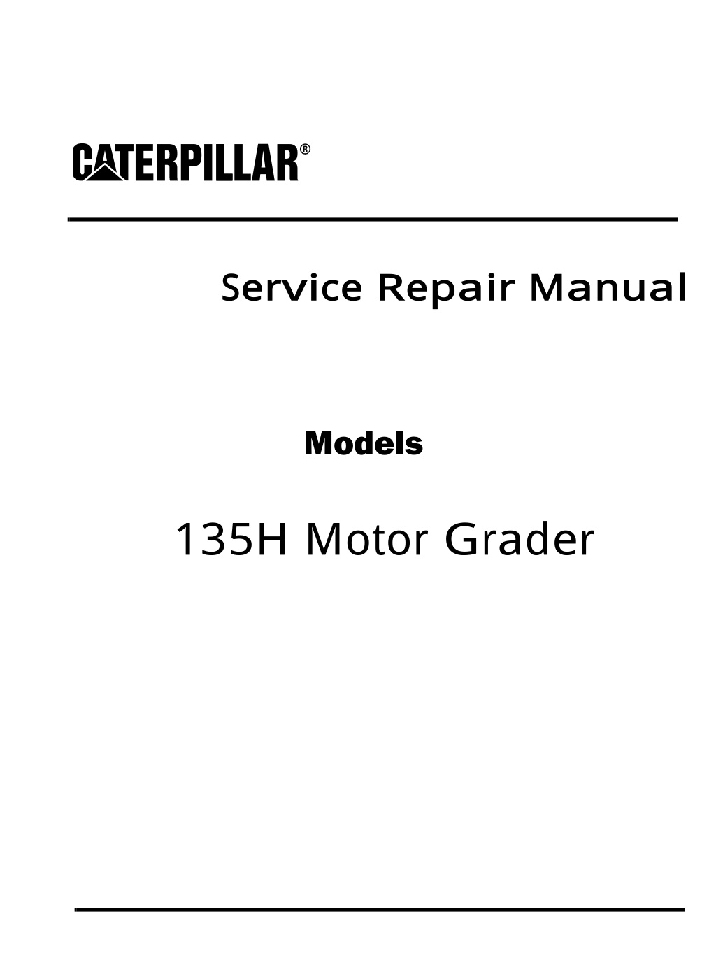
Service Repair Manual Models 135H M otor Grader
135H Motor Grader CBC00001-UP (MACHINE) POWERED BY 3126B Engine(SEB... 1/9 Shutdown SIS Previous Screen Product: MOTOR GRADER Model: 135H MOTOR GRADER CBC Configuration: 135H Motor Grader CBC00001-UP (MACHINE) POWERED BY 3126B Engine Disassembly and Assembly 120H and 135H Motor Graders Power Train Media Number -RENR4160-05 Publication Date -01/04/2005 Date Updated -22/05/2017 i05371526 Final Drive - Assemble SMCS - 4050-016 Assembly Procedure Table 1 Required Tools Tool Part Number Part Description Qty A 439-3938 Link Bracket 2 B 5P-4204 Wrench Assembly 1 C 6V-4876 Lubricant 1 D 8T-5096 Dial Indicator Gp 1 Note: Use a suitable press to install the cones on the drive shafts and the cups. If necessary, only preheat the cones to 135 C (275 F) for no more than 1 hour. It is important to reseat the cone or the cup with a suitable driver after the bearing and adjacent parts have reached a uniform temperature. https://127.0.0.1/sisweb/sisweb/techdoc/techdoc_print_page.jsp?returnurl=/sisw... 2020/2/6
135H Motor Grader CBC00001-UP (MACHINE) POWERED BY 3126B Engine(SEB... 2/9 Illustration 1 g01060675 Illustration 2 g01060676 1. Lower the temperature of bearing cup (32) and install bearing cup (32) in housing (29). Check for full seating of the bearing cup with a Feeler Gauge. Illustration 3 g01060678 https://127.0.0.1/sisweb/sisweb/techdoc/techdoc_print_page.jsp?returnurl=/sisw... 2020/2/6
https://www.ebooklibonline.com Hello dear friend! Thank you very much for reading. Enter the link into your browser. The full manual is available for immediate download. https://www.ebooklibonline.com
135H Motor Grader CBC00001-UP (MACHINE) POWERED BY 3126B Engine(SEB... 3/9 2. Place housing (29) in a vertical position with the flange downward. 3. Install lip seal (31) in housing (29). The lip of the seal must face outward. Lubricate the lip seal (31) with the lubricant which is being sealed. 4. Lower the temperature of bearing cup (30) and install bearing cup (30) in housing (29). Check for full seating of the bearing cup with a Feeler Gauge. Illustration 4 g02782189 5. Apply Tooling (C) onto thrust washer (28). Apply Tooling (C) onto surface (X) and surface (Y). Install thrust washer (18). Illustration 5 g02782206 6. Install lip seal (25) into housing (26). Illustration 6 g02783199 https://127.0.0.1/sisweb/sisweb/techdoc/techdoc_print_page.jsp?returnurl=/sisw... 2020/2/6
135H Motor Grader CBC00001-UP (MACHINE) POWERED BY 3126B Engine(SEB... 4/9 7. Turn over housing (26). Install wear sleeves (27). The diagonal cuts that are in wear sleeves (27) are separated by 90 . Apply Tooling (C) onto thrust washer (24). Install thrust washer (24). Illustration 7 g02783245 8. Use Tooling (A) and a suitable lifting device to install housing (26). The weight of housing (26) is approximately 54 kg (120 lb). Install shims (23A). Use a suitable soft hammer to drive the wear sleeves into housing (26) until the sleeves are flush with the top of the bore surface. Do not install the shims at this time. Illustration 8 g02783255 9. Drill three equally spaced 8 mm (5/16 inch) holes in retainer (23) if necessary. The holes must be centered on the existing bolt hole pattern and perpendicular to each surface. 10. Measure the thickness of retainer (23) at the three hole locations. Average the three measurements and record the result as Dimension (A). https://127.0.0.1/sisweb/sisweb/techdoc/techdoc_print_page.jsp?returnurl=/sisw... 2020/2/6
135H Motor Grader CBC00001-UP (MACHINE) POWERED BY 3126B Engine(SEB... 5/9 Illustration 9 g02783265 11. Install retainer (23). Install three of bolts (22). Tighten bolts (22) to a torque of 50 7 N m (37 5 lb ft). Completely loosen bolts (22). Finger tighten bolts (22). Use Tooling (D) to measure the gap between the top surface of retainer (23) and the final drive housing at the three 8 mm (5/16 inch) hole locations. Record the measurement from each of the three locations as the nominal gap or Dimension (B). 12. Calculate the shim pack thickness for the three measurement locations by subtracting Dimension (A) from the Dimension (B) giving you Dimension (C). Remove bolts (22) and retainer (23). Illustration 10 g02783317 13. Install various shims (23A) that is equal to Dimension (C) plus + 0.075 - 0.025 mm (+ 0.003 - 0.001 inch). Install retainer (23). Install bolts (22). Tighten bolts (22) to a torque of 270 40 N m (199 30 lb ft). Illustration 11 g01060689 https://127.0.0.1/sisweb/sisweb/techdoc/techdoc_print_page.jsp?returnurl=/sisw... 2020/2/6
135H Motor Grader CBC00001-UP (MACHINE) POWERED BY 3126B Engine(SEB... 6/9 Illustration 12 g01060690 14. Preheat and install bearing cone (21) on drive shaft (20). Check for full seating of the cone with a Feeler Gauge. With the drive shaft in a vertical position, set the housing on bearing cone (21). 15. Start bearing cone (33) (not shown) on the top of drive shaft (20). Do not preheat this bearing cone. The bearing cone can be seated in position by using the sprocket during Step 17. Make sure that the bearing cone is seated in the cup. 16. Install drive shaft (20) in housing assembly (2). Illustration 13 g01060692 Illustration 14 g01060693 17. Place the first sprocket (19) on drive shaft (20). The large diameter must face downward. 18. Place the second sprocket (19) on drive shaft (20). The hub must face downward and the large diameter must face upward. Ensure that the lubrication holes (X) for the spline are aligned. https://127.0.0.1/sisweb/sisweb/techdoc/techdoc_print_page.jsp?returnurl=/sisw... 2020/2/6
135H Motor Grader CBC00001-UP (MACHINE) POWERED BY 3126B Engine(SEB... 7/9 19. Install nut (17) to the drive shaft (20). Rotate drive shaft (20) and hit the hub of sprockets (19) while nut (17) is being tightened to a torque of 11 1 N m (100 10 lb in) above seal drag. 20. Loosen nut (17) by one locking position. Hit the hub of sprockets (19) again. 21. The final torque that is needed to rotate shaft (20) should be 2 1 N m (20 10 lb in) or 3.95 1.13 N m (35 10 lb in)above the seal drag depending on machine model. Table 2 Model Rolling Torque 120H, 120K, 135H 2.95 1.13 N m (26 10 lb in) 12H, 12K, 140H, 140K, 143H, 160H, 160K, 163H 3.95 1.13 N m (35 10 lb in) Note: Refer to Testing and Adjusting, "Final Drive Bearings - Adjust" for bearing adjustments when the final drive is in chassis. 22. Install bolt (18), the washer, and lock (16) which holds nut (17) to the drive shaft (20). Tighten bolt (18) to a torque of 50 10 N m (37 7 lb ft). Illustration 15 g00621112 23. Position ring gear (15) to housing assembly (2). 24. Install bolts (13), the washers, and plates (14) to hold ring gear (15) to housing assembly (2). Tighten locking bolts (13) to a torque of 50 10 N m (37 7 lb ft). Illustration 16 g00621111 25. Install washer (12) and retaining ring (11) in planetary carrier (3). https://127.0.0.1/sisweb/sisweb/techdoc/techdoc_print_page.jsp?returnurl=/sisw... 2020/2/6
135H Motor Grader CBC00001-UP (MACHINE) POWERED BY 3126B Engine(SEB... 8/9 Illustration 17 g00621108 Illustration 18 g00621109 26. Install gear assemblies (7) and planetary shafts (4) in planetary carrier (3). Note: Each gear assembly (7) consists of two washers (8), two roller assemblies (9), planetary gear (10), and planetary shaft (4). 27. Install retainers (6), the washers, and locking bolts (5) to planetary carrier (3) to hold planetary shafts (4) and gear assemblies (7) in planetary carrier (3). Tighten locking bolts (5) to a torque of 50 10 N m (37 7 lb ft). Illustration 19 g00621106 28. Install planetary carrier (3) in housing assembly (2). 29. Install sun gear shaft (1) in housing assembly (2). https://127.0.0.1/sisweb/sisweb/techdoc/techdoc_print_page.jsp?returnurl=/sisw... 2020/2/6
135H Motor Grader CBC00001-UP (MACHINE) POWERED BY 3126B Engine(SEB... 9/9 30. Repeat Steps 21 through 29 to assemble the remaining final drive. End By: a. Install the final drives. Copyright 1993 - 2020 Caterpillar Inc. Thu Feb 6 09:53:25 UTC+0800 2020 All Rights Reserved. Private Network For SIS Licensees. https://127.0.0.1/sisweb/sisweb/techdoc/techdoc_print_page.jsp?returnurl=/sisw... 2020/2/6
135H Motor Grader CBC00001-UP (MACHINE) POWERED BY 3126B Engine(SEB... 1/2 Shutdown SIS Previous Screen Product: MOTOR GRADER Model: 135H MOTOR GRADER CBC Configuration: 135H Motor Grader CBC00001-UP (MACHINE) POWERED BY 3126B Engine Disassembly and Assembly 120H and 135H Motor Graders Power Train Media Number -RENR4160-05 Publication Date -01/04/2005 Date Updated -22/05/2017 i01981721 Final Drive - Install SMCS - 4050-012 Installation Procedure Note: Cleanliness is an important factor. Before assembly, all parts should be thoroughly cleaned in cleaning fluid. Allow the parts to air dry. Wiping cloths or rags should not be used to dry parts. Lint may be deposited on the parts which may cause later trouble. Inspect all parts. If any parts are worn or damaged, use new parts for replacement. https://127.0.0.1/sisweb/sisweb/techdoc/techdoc_print_page.jsp?returnurl=/sisw... 2020/2/6
135H Motor Grader CBC00001-UP (MACHINE) POWERED BY 3126B Engine(SEB... 2/2 Illustration 1 g00999500 1. Attach a suitable lifting device to final drive (1). The weight of final drive (1) is approximately 272 kg (600 lb). 2. Use pry bars (3) in order to balance final drive (1). Install final drive (1). Install nuts (2). Tighten nuts (2) to a torque of 240 40 N m (177 30 lb ft). 3. Fill the power train oil system. The capacity of the power train system is 47 L (12 US gal). End By: a. Install the tandem housing. Refer to Disassembly and Assembly, "Tandem Housing - Install". Copyright 1993 - 2020 Caterpillar Inc. Thu Feb 6 09:54:21 UTC+0800 2020 All Rights Reserved. Private Network For SIS Licensees. https://127.0.0.1/sisweb/sisweb/techdoc/techdoc_print_page.jsp?returnurl=/sisw... 2020/2/6
135H Motor Grader CBC00001-UP (MACHINE) POWERED BY 3126B Engine(SEB... 1/2 Shutdown SIS Previous Screen Product: MOTOR GRADER Model: 135H MOTOR GRADER CBC Configuration: 135H Motor Grader CBC00001-UP (MACHINE) POWERED BY 3126B Engine Disassembly and Assembly 120H and 135H Motor Graders Power Train Media Number -RENR4160-05 Publication Date -01/04/2005 Date Updated -22/05/2017 i01924681 Transmission Oil Filter Base - Remove SMCS - 3068-011 Removal Procedure Table 1 Required Tools Tool Part Number Part Description Qty 6V-9511 Face Seal Plug 1 6V-9512 Face Seal Plug 1 ZZ 6V-9832 Cap As 1 6V-9833 Cap As 1 Note: SERVICE DATA: TOOLING (ZZ) WILL NOT BE IDENTIFIED IN PHOTOGRAPHS IN THE REMOVAL OR THE INSTALLATION. THIS TOOLING IS SHOWN IN ORDER TO ASSIST THE EXPERIENCED SERVICEMAN. Note: Cleanliness is an important factor. Before the disassembly procedure, the exterior of the component should be thoroughly cleaned. This will help to prevent dirt from entering the internal mechanism. NOTICE Care must be taken to ensure that fluids are contained during performance of inspection, maintenance, testing, adjusting and repair of the product. Be prepared to collect the fluid with suitable containers before opening any compartment or disassembling any component containing fluids. https://127.0.0.1/sisweb/sisweb/techdoc/techdoc_print_page.jsp?returnurl=/sisw... 2020/2/6
135H Motor Grader CBC00001-UP (MACHINE) POWERED BY 3126B Engine(SEB... 2/2 Refer to Special Publication, NENG2500, "Caterpillar Dealer Service Tool Catalog" for tools and supplies suitable to collect and contain fluids on Caterpillar products. Dispose of all fluids according to local regulations and mandates. Note: Put identification marks on all lines, on all hoses, on all wires, and on all tubes for installation purposes. Plug all lines, hoses, and tubes. This helps to prevent fluid loss and this helps to keep contaminants from entering the system. Illustration 1 g01001711 1. Disconnect harness assembly (1). 2. Disconnect hose (2) from the rear chassis support. Disconnect hose assemblies (3). 3. Remove bolts (4). Remove filter (5) and the base. Copyright 1993 - 2020 Caterpillar Inc. Thu Feb 6 09:55:17 UTC+0800 2020 All Rights Reserved. Private Network For SIS Licensees. https://127.0.0.1/sisweb/sisweb/techdoc/techdoc_print_page.jsp?returnurl=/sisw... 2020/2/6
135H Motor Grader CBC00001-UP (MACHINE) POWERED BY 3126B Engine(SEB... 1/5 Shutdown SIS Previous Screen Product: MOTOR GRADER Model: 135H MOTOR GRADER CBC Configuration: 135H Motor Grader CBC00001-UP (MACHINE) POWERED BY 3126B Engine Disassembly and Assembly 120H and 135H Motor Graders Power Train Media Number -RENR4160-05 Publication Date -01/04/2005 Date Updated -22/05/2017 i01925533 Transmission Oil Filter Base - Disassemble SMCS - 3068-015 Disassembly Procedure Table 1 Required Tools Tool Part Number Part Description Qty A 1P-1855 Retaining Ring Pliers 1 B 1P-1853 Retaining Ring Pliers 1 Start By: a. Remove the transmission oil filter base. Refer to Disassembly and Assembly, "Transmission Oil Filter Base - Remove". Note: Cleanliness is an important factor. Before the disassembly procedure, the exterior of the component should be thoroughly cleaned. This will help to prevent dirt from entering the internal mechanism. https://127.0.0.1/sisweb/sisweb/techdoc/techdoc_print_page.jsp?returnurl=/sisw... 2020/2/6
135H Motor Grader CBC00001-UP (MACHINE) POWERED BY 3126B Engine(SEB... 2/5 Illustration 1 g01002179 1. Drain the oil from the filter base assembly (1). Remove fitting assembly (2). Illustration 2 g01002180 2. Remove hose clamp (3), hose (4), and O-ring seal (5). Illustration 3 g01002181 3. Remove fitting assemblies (6) and remove O-ring seals (7). Illustration 4 g01002182 https://127.0.0.1/sisweb/sisweb/techdoc/techdoc_print_page.jsp?returnurl=/sisw... 2020/2/6
135H Motor Grader CBC00001-UP (MACHINE) POWERED BY 3126B Engine(SEB... 3/5 4. Remove housing (8) and element (9). Illustration 5 g01002183 5. Use Tooling (A) to remove ring (10). Remove retainer (11) and remove spring (12). Illustration 6 g01002184 Personal injury can result from being struck by parts propelled by a released spring force. Make sure to wear all necessary protective equipment. Follow the recommended procedure and use all recommended tooling to release the spring force. 6. Remove switch (13), spool (14), and spring (15). https://127.0.0.1/sisweb/sisweb/techdoc/techdoc_print_page.jsp?returnurl=/sisw... 2020/2/6
135H Motor Grader CBC00001-UP (MACHINE) POWERED BY 3126B Engine(SEB... 4/5 Illustration 7 g01002872 7. Remove O-ring seal (16). Remove ring (17) with Tooling (B). Remove valve (18) and spring (19). Illustration 8 g01002875 8. Remove plug (20) and O-ring seal (21). Illustration 9 g01002876 9. Remove fitting assemblies (22) and O-ring seals (23). https://127.0.0.1/sisweb/sisweb/techdoc/techdoc_print_page.jsp?returnurl=/sisw... 2020/2/6
135H Motor Grader CBC00001-UP (MACHINE) POWERED BY 3126B Engine(SEB... 5/5 Illustration 10 g01002878 10. Remove O-ring seal (24). Copyright 1993 - 2020 Caterpillar Inc. Thu Feb 6 09:56:13 UTC+0800 2020 All Rights Reserved. Private Network For SIS Licensees. https://127.0.0.1/sisweb/sisweb/techdoc/techdoc_print_page.jsp?returnurl=/sisw... 2020/2/6
Suggest: If the above button click is invalid. Please download this document first, and then click the above link to download the complete manual. Thank you so much for reading
135H Motor Grader CBC00001-UP (MACHINE) POWERED BY 3126B Engine(SEB... 1/5 Shutdown SIS Previous Screen Product: MOTOR GRADER Model: 135H MOTOR GRADER CBC Configuration: 135H Motor Grader CBC00001-UP (MACHINE) POWERED BY 3126B Engine Disassembly and Assembly 120H and 135H Motor Graders Power Train Media Number -RENR4160-05 Publication Date -01/04/2005 Date Updated -22/05/2017 i01925536 Transmission Oil Filter Base - Assemble SMCS - 3068-016 Installation Procedure Table 1 Required Tools Tool Part Number Part Description Qty A 1P-1855 Retaining Ring Pliers 1 B 1P-1853 Retaining Ring Pliers 1 Note: Cleanliness is an important factor. Before assembly, all parts should be thoroughly cleaned in cleaning fluid. Allow the parts to air dry. Wiping cloths or rags should not be used to dry parts. Lint may be deposited on the parts which may cause later trouble. Inspect all parts. If any parts are worn or damaged, use new parts for replacement. Illustration 1 g01002878 https://127.0.0.1/sisweb/sisweb/techdoc/techdoc_print_page.jsp?returnurl=/sisw... 2020/2/6
https://www.ebooklibonline.com Hello dear friend! Thank you very much for reading. Enter the link into your browser. The full manual is available for immediate download. https://www.ebooklibonline.com

 POWERED BY 3126B")
 POWERED BY 3126B")

 POWERED BY 3126B")
 POWERED BY 3126B")
 POWERED BY 3126B")
 POWERED BY 3126B")
 POWERED BY 3126B")
 POWERED BY 3126B")
 POWERED BY 3126B")
 POWERED BY 3126B")
 POWERED BY 3126B")
 POWERED BY 3126B")
 POWERED BY 3126B")
 POWERED BY 3126B")
 POWERED BY 3126B")
 POWERED BY 3126B")
 POWERED BY 3126B")
 POWERED BY 3126B")

 POWERED BY 3126B")