Understanding Harmonics in Electromagnetic Environments

In the realm of electromagnetic environments, the generation of electromagnetic interference (EMI) through harmonics plays a crucial role. This article delves into the concept of harmonics, their generation in simple DC power supplies, and the impact they have on electronic devices. From the basics of harmonic frequencies to Fourier analysis of complex waveforms, readers gain insights into the complexities of managing harmonics for maintaining electromagnetic compatibility (EMC). Exploring waveforms, phase angles, and frequency spectra, the importance of addressing harmonics in electronic design is highlighted for a clearer understanding of EMI issues.

Download Presentation

Please find below an Image/Link to download the presentation.
The content on the website is provided AS IS for your information and personal use only. It may not be sold, licensed, or shared on other websites without obtaining consent from the author. Download presentation by click this link. If you encounter any issues during the download, it is possible that the publisher has removed the file from their server.
E N D
Presentation Transcript
EMI GENERATION Consider the simple DC power supply consisting of nothing more than a transformer, bridge rectifier, reservoir capacitor and load resistor (see Figure 1). At first sight a simple circuit of this type may look somewhat benign, but just take a look at the waveforms shown in Figure 2. The primary and secondary voltage waveforms are both sinusoidal and, as you might expect, the load voltage comprises a DC level (just less than the peak secondary voltage) onto which is superimposed a ripple component at 800 Hz. What s more significant (in terms of EMC and EMI) is the waveform of the current that flows in both the secondary and primary circuits. Rather than being sinusoidal (as you might have thought) this current comprises a series of fast rise-time rectangular pulses as each pair of diodes conducts alternately in order to replace the lost charge in the reservoir capacitor. Unfortunately, these rectangular pulses contain numerous harmonics.
HARMONICS An integer multiple of a fundamental frequency is known as a harmonic. In addition, we often specify the order of the harmonic (second, third, and so on). Thus the second harmonic has twice the frequency of the fundamental, the third harmonic has three times the frequency of the fundamental, and so on. Consider, for example, a fundamental signal at 1 kHz. The second harmonic would have a frequency of 2 kHz, the third harmonic a frequency of 3 kHz and the fourth harmonic a frequency of 4 kHz. Note that, in musical terms, the relationship between notes that are one octave apart is simply that the two frequencies have a ratio of 2:1 (in other words, the higher frequency is double the lower frequency).
HARMONICS All complex waveforms (of which rectangular pulses and square waves are examples) comprise a fundamental component together with a number of harmonic components, each having a specific amplitude and with a specific phase relative to the fundamental. The mathematical study of complex waves is known as Fourier analysis and this allows us to describe a complex wave using an equation of the form: ? = ????? (??) + ????? (?? ??) + ????? (?? ??) + where v is the instantaneous voltage of the complex waveform at time, t. V1 is the amplitude of the fundamental, V2 is the amplitude of the second harmonic, V3 is the amplitude of the third harmonic, and so on.
HARMONICS Similarly, ?? is the phase angle of the second harmonic (relative to the fundamental), ?? is the phase angle of the third harmonic (relative to the fundamental), and so on. The important thing to note from this is that all of the individual components that go to make up a complex waveform have a sine wave shape. Putting this another way, a complex wave is made up from a number of sine waves. Frequency spectrum of a pulse : A rectangular pulse comprises a fundamental component together with an infinite series of harmonics. Taking a square wave as an extreme example of a rectangular pulse, the composite waveform can be analyzed into the following components:
HARMONICS a fundamental component at a frequency, f, and amplitude, V; a third harmonic component at a frequency, 3f, and amplitude V/3; a fifth harmonic component at a frequency, 5f, and amplitude, V/5; a seventh harmonic component at a frequency, 7f, and amplitude, V/7; This process (up to the seventh harmonic) is shown in Figure 3. The corresponding frequency frequency) appears in Figure 4. Note that, to produce a perfect square wave, the amplitude of the harmonics should decay in accordance with their harmonic order and they must all be in phase with the fundamental. spectrum (showing amplitude plotted against Using Fourier analysis, the equation for a square wave voltage is:
HARMONICS ? = ???? ?? +? ???? ??? +? ???? ??? + where V is the amplitude of the fundamental and ? is the angular frequency of the fundamental (note that ? = 2 f , where f is the frequency of the fundamental).
EMC AND AVIONIC EQUIPMENT In recent years, EMC and EMI have become a very important consideration for avionic equipment designers. To ensure compliance with increasingly demanding standards, it has become essential for designers to consider the effects of unwanted signals generated by avionic equipment, as well as the susceptibility of the equipment to interference from outside. To illustrate this important point we will again use the example of the simple low- voltage DC power supply that we met in Figure1. For this unit to meet stringent EMC requirements it needs to be modified as shown in Figure 5.The additional components have the following functions:
EMC AND AVIONIC EQUIPMENT 1. C5, C6, C7 and C8 provide additional decoupling (effective at high frequencies) in order to prevent instability in IC1 and IC2.Without these components, and depending upon circuit layout (stray reactance) the regulator circuits may oscillate at a high frequency. 2. C9 and C10 provide additional high-frequency decoupling to remove noise present on the output voltage rails. 3. C11, L1, L2, C12 and C13 provide a low-pass supply filter to remove noise and spurious signals resulting from the harmonics of the switching action of the diode rectifiers. This filter also reduces supply-borne noise that would otherwise enter the equipment from the supply. 4. A low-resistance ground connection is introduced to ensure that there is an effective connection between aircraft ground and the equipment chassis (note that there is also an earth connection to the laminations and internal screening on the mains transformer).
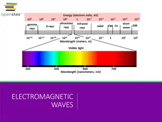
FREQUENCY BANDS For convenience the complete frequency spectrum is divided into a number of bands. These bands are often referred to when describing the effects of particular types of EMI, and they are shown in Table 1
EFFECTS AND CAUSES OF EMI EMI can be defined as the presence of unwanted voltages or currents which can adversely affect the performance of an avionic system. The effects of EMI include errors in instrument indications (both above and below true), heterodyne whistles present on audio signals, herringbone patterns in video displays, repetitive pulse noise (buzz) on intercom and cabin phone systems, desensitizing of radio and radar receivers, false indications in radar and distance measuring equipment, unwarranted triggering of alarms, and so on. Note that, in certain circumstances, the performance of the device that emits EMI may also suffer impaired performance.
SOURCES OF EMI Some sources known to emit EMI include fluorescent lights, radio and radar transmitters, power lines, window heat controllers, induction motors, switching and light-dimming circuits, microprocessors and associated circuitry, pulsed high- frequency circuits, bus cables (but not fiber-optic cables), static discharge and lightning. The energy generated by these sources can be conducted and/or radiated as an electromagnetic field. Unless adequate precautions are taken to eliminate the interference at source and/or to reduce the equipment s susceptibility to EMI, the energy can then become coupled into other circuits. Conduction is the process by which the energy is transmitted through electrically conductive paths such as circuit wiring or aircraft metallic structure. In electromagnetic field radiation, energy is transmitted through electrically non- conductive paths, such as air, plastic materials or fiberglass.
SOURCES OF EMI Systems which may be susceptible to electromagnetic interference include radio and radar receivers, microprocessors and other instruments, control systems, audio and inflight entertainment systems (IFEs). microelectronic systems, electronic Whether a system will have an adverse response to depends on the type and amount of emitted energy in conjunction with the susceptibility threshold of the receiving system. electromagnetic interference The threshold of susceptibility is the minimum interference signal level (conducted or radiated) that results in equipment performance that is indistinguishable from the normal response. If the threshold is exceeded then the performance of the equipment will become degraded. Note that when the susceptibility threshold level is greater than the levels of conducted or radiated emissions, electromagnetic interference problems do not exist. Systems to which this applies are said to be electromagnetically compatible. In other words, the systems will operate as intended and any EMI generated is at such a level that it does affect normal operation.
TYPES OF INTERFERENCE EMI can be categorized by bandwidth, amplitude, waveform and occurrence. The bandwidth of interference is the frequency range in which the interference exists. The interference bandwidth can be narrow or broad. Narrowband interference can be caused by such items as AC power rails, microprocessor clocks (and their harmonics), radio transmitters and receivers. These items of equipment all contain sources (e.g. clock oscillators) that work on specific frequencies. These signals (along with unwanted harmonics) can be radiated at low levels from the equipment. Broadband interference is caused by devices generating random frequencies and noise which may be repetitive but is not confined to a single frequency or range of frequencies. Examples of this type of interference are power supplies, LCD and AMLCD (by virtue of their high-frequency AC supplies), switched mode power supplies, switching power controllers and microprocessor bus systems.
TYPES OF INTERFERENCE Interference amplitude is the strength of the signal received by the susceptible system. The amplitude can be constant or can vary predictably with time, or can be totally random. For example, a 115 V AC power line can induce a stable sinusoidal waveform on adjacent 28 V DC power or signal lines. The amplitude of the interference will depend on the load current in the AC power line (recall that the magnetic field produced around a conductor is directly proportional to the current flowing in the conductor). Examples of random interference are environmental noise and inductive switching transients. Environmental noise is the aggregate of all electromagnetic emissions present in a particular space or area of concern at any one time. This is usually measured over a defined spectrum (e.g. 30 kHz to 30 MHz).
TYPES OF INTERFERENCE It is important to be aware that there is no one specific waveform that produces electromagnetic interference. Instead, it is the change from one signal level to another in conjunction with the rate at which it changes that determines the amount of electromagnetic energy released. More energy is released when the change in signal level and rate is increased. The occurrence of EMI can be categorized as being either periodic (continuously repetitive), aperiodic (predictable but unpredictable). not continuous), or random (totally
EMI REDUCTION Planning for electromagnetic compatibility must be initiated in the design phase of a device or system. If this is not satisfactorily achieved, interference problems may arise. The three factors necessary to produce an EMI problem are a noise source , a means of coupling (by conduction or radiation) and a susceptible receiver. To reduce the effects of EMI, at least one of these factors must be addressed. The following lists techniques for EMI reduction under these three headings : 1. Suppress interference at source. Enclose interference source in a screened metal enclosure and then ensure that the enclosure is adequately grounded. Use transient suppression on relays, switches and contactors. Twist and/or shield bus wires and data bus connections. Use screened (i.e. coaxial) cables for audio and radio frequency signals.
EMI REDUCTION Use screened (i.e. coaxial) cables for audio and radio frequency signals. Keep pulse rise times as slow and long as possible. Check that enclosures, racks and other supporting structures are grounded effectively. 2. Reduce noise coupling. Separate power leads from interconnecting signal wires. Twist and/or shield noisy wires and data bus connections. Fit an optical fiber data bus where possible. Use screened (i.e. coaxial) cables for audio and radio frequency signals. Keep ground leads as short as possible. Break interference ground loops by incorporating isolation transformers, differential amplifiers and balanced circuits. Filter noisy output leads.
EMI REDUCTION Physically relocate receivers and sensitive Break interference ground loops by incorporating isolation transformers, differential amplifiers and balanced circuits. Filter noisy output leads. Physically relocate receivers and sensitive equipment away from interference source. 3. Increasing susceptibility thresholds. Limit bandwidth to only that which is strictly necessary. Limit gain and sensitivity to only that which is strictly necessary. Ensure that enclosures are grounded and that internal screens are fitted. Fit components that are inherently less susceptible to the effect of stray radiated fields.
AIRCRAFT WIRING AND CABLING When many potential sources of EMI are present in a confined space, aircraft wiring and cabling has a crucial role to play in maintaining electromagnetic compatibility. The following points should be observed: 1. Adequate wire separation should be maintained between noise source wiring and susceptible wiring (for example, ADF wiring should be strategically routed in the aircraft to ensure a high level of EMC). 2. Any changes to the routing of this wiring could have an adverse affect on the system. In addition, the wire separation requirements for all wire categories must be maintained. 3. Wire lengths should be kept as short as possible to keep coupling at a minimum. Where wire shielding is incorporated for lightning protection, it is important that the shield grounds (pigtails) be kept to their designed length. An inch or two added to the length will result in degraded lightning protection.
AIRCRAFT WIRING AND CABLING 4. Equipment grounds must not be lengthened beyond design specification. A circuit ground with too much impedance may no longer be a true ground. 5. With the aid of the technical manuals, grounding and bonding integrity must be maintained. This includes proper preparation of the surfaces where electrical bonding is made.
GROUNDING AND BONDING The electrical integrity of the aircraft structure is extremely important as a means of reducing EMI and also protecting the aircraft, its passengers, crew and systems from the effects of lightning strikes and static discharge. Grounding and bonding are specific techniques that are used to achieve this (see Figure). Grounding and bonding can also be instrumental in minimizing the effects of high- intensity radio frequency fields (HIRF) emanating from high-power radio transmitters and radar equipment. Grounding and bonding resistances of less than 0.001 0.003W are usually required.
GROUNDING Grounding is defined as the process of electrically connecting conductive objects to either a conductive structure or some other conductive return path for the purpose of safely completing either a normal or fault circuit. Bonding and grounding connections are made in an aircraft in order to accomplish the following: protect aircraft, crew and passengers against the effects of lightning discharge; provide return paths for current; prevent the development of RF voltages and currents; protect personnel from shock hazards; maintain an effective radio transmission and reception capability; prevent accumulation of static charge.
GROUNDING The following general procedures and precautions apply when making bonding or grounding connections: bond or ground parts to the primary aircraft structure where possible; make bonding or grounding connections so that no part of the aircraft structure is weakened; bond parts individually if feasible; install bonding or grounding connections against smooth, clean surfaces; install bonding or grounding connections so that vibration, expansion or contraction, or relative movement in normal service, will not break or loosen the connection; check the integrity and effectiveness of a bonded or grounded connection using an approved bonding tester.
BONDING Bonding refers to the electrical connecting of two or more conducting objects that are not otherwise adequately connected. The main types of bonding are: Equipment bonding: low-impedance paths to the aircraft structure are generally required for electronic equipment to provide radio frequency return circuits and to facilitate reduction in EMI. Metallic surface bonding: all conducting objects located on the exterior of the airframe should be electrically connected to the airframe through mechanical joints, conductive hinges or bond straps, which are capable of conducting static charges and lightning strikes. Static bonds : All isolated conducting paths inside and outside the aircraft with an area greater than three square inches and a linear dimension over three inches that are subjected to electrostatic charging should have a mechanically secure electrical connection to the aircraft structure of adequate conductivity to dissipate possible static charges.