New Holland CR9070 Elevation Combine Harvesters Service Repair Manual
To get the complete manual, please open the home page website.nnhttps://www.aservicemanualpdf.com/

Uploaded on | 6 Views
Download Presentation

Please find below an Image/Link to download the presentation.
The content on the website is provided AS IS for your information and personal use only. It may not be sold, licensed, or shared on other websites without obtaining consent from the author. Download presentation by click this link. If you encounter any issues during the download, it is possible that the publisher has removed the file from their server.
E N D
Presentation Transcript
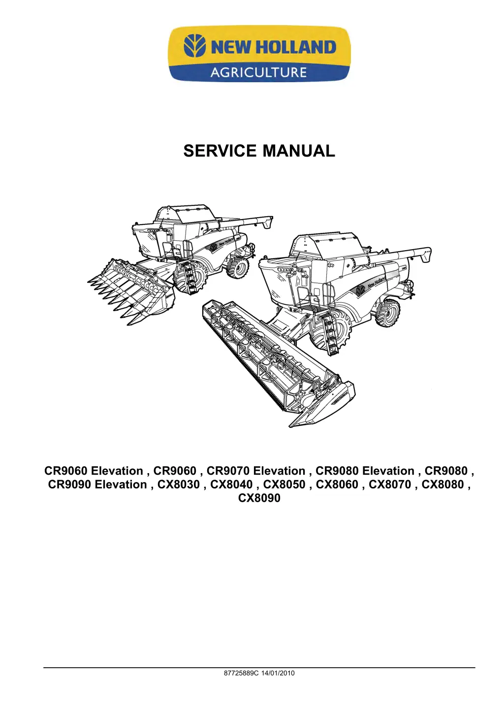
SERVICE MANUAL CR9060 Elevation , CR9060 , CR9070 Elevation , CR9080 Elevation , CR9080 , CR9090 Elevation , CX8030 , CX8040 , CX8050 , CX8060 , CX8070 , CX8080 , CX8090 87725889C 14/01/2010
Contents INTRODUCTION DISTRIBUTION SYSTEMS.............................................................A PRIMARY HYDRAULIC POWER SYSTEM............................................... A.10.A SECONDARY HYDRAULIC POWER SYSTEM........................................... A.12.A HYDRAULIC COMMAND SYSTEM....................................................... A.14.A PNEUMATIC SYSTEM .................................................................... A.20.A ELECTRICAL POWER SYSTEM ......................................................... A.30.A LIGHTING SYSTEM....................................................................... A.40.A ELECTRONIC SYSTEM .................................................................. A.50.A FAULT CODES ............................................................................ A.50.A POWER PRODUCTION.................................................................B ENGINE ................................................................................... B.10.A FUEL AND INJECTION SYSTEM......................................................... B.20.A AIR INTAKE SYSTEM..................................................................... B.30.A EXHAUST SYSTEM....................................................................... B.40.A ENGINE COOLANT SYSTEM ............................................................ B.50.A ENGINE CLEANING SYSTEM Blow off system .......................................... B.62.B STARTING SYSTEM ...................................................................... B.80.A POWER TRAIN.............................................................................C POWER COUPLING Fixed coupling ......................................................C.10.B TRANSMISSION Mechanical .............................................................C.20.B TRANSMISSION Hydrostatic.............................................................. C.20.F PROCESS DRIVE Primary process drive.................................................C.50.B TRAVELLING................................................................................D FRONT AXLE .............................................................................D.10.A REAR AXLE ...............................................................................D.12.A 2WD-4WD SYSTEM Hydrostatic..........................................................D.14.E STEERING Hydraulic..................................................................... D.20.C STEERING AutoPilot......................................................................D.20.E 87725889C 14/01/2010
SERVICE BRAKE Hydraulic.............................................................. D.30.C PARKING BRAKE Hydraulic ............................................................. D.32.C BODY AND STRUCTURE ..............................................................E SHIELD.................................................................................... E.20.A OPERATOR AND SERVICE PLATFORM................................................. E.30.A USER CONTROLS AND SEAT ........................................................... E.32.A USER CONTROLS AND SEAT Operator seat ............................................E.32.C USER PLATFORM ........................................................................ E.34.A ENVIRONMENT CONTROL Heating system ............................................. E.40.B ENVIRONMENT CONTROL Air-conditioning system.....................................E.40.C ENVIRONMENT CONTROL Heating, ventilation and air-conditioning....................E.40.D SAFETY SECURITY ACCESSORIES Safety............................................. E.50.B TOOL POSITIONING.................................................................... G LIFTING .................................................................................. G.10.A LEVELLING .............................................................................. G.30.A CROP PROCESSING....................................................................K FEEDING Header feeding.................................................................K.25.D FEEDING Feeder housing ................................................................ K.25.E FEEDING Rotor feeding...................................................................K.25.N THRESHING Conventional threshing ..................................................... K.40.B THRESHING Twin flow threshing .........................................................K.40.D SEPARATING Beating..................................................................... K.42.B SEPARATING Rotary separator...........................................................K.42.C SEPARATING Twin flow rotor .............................................................K.42.D SEPARATING Straw walker............................................................... K.42.E SEPARATING Straw flow beater .......................................................... K.42.F SEPARATING Discharge beater ......................................................... K.42.G STORING AND HANDLING Grain storing ................................................ K.60.B CLEANING Primary cleaning.............................................................. K.62.B 87725889C 14/01/2010
https://www.aservicemanualpdf.com/ My Dear Friend! Thank you very much for visiting. Full manual if required, please enter the following URL into your browser. https://www.aservicemanualpdf.com/
CLEANING Tailings return system ........................................................K.62.C RESIDUE HANDLING Straw chopper.....................................................K.64.C RESIDUE HANDLING Spreader ..........................................................K.64.D RESIDUE HANDLING Chaff blower....................................................... K.64.F RESIDUE HANDLING Chaff spreader ................................................... K.64.G RESIDUE HANDLING Positive straw discharge (PSD) ...................................K.64.H UNLOADING Grain unloading............................................................. K.72.B PROTECTION SYSTEMS Reversing system.............................................K.90.C PROTECTION SYSTEMS Stone trapping ................................................ K.90.E 87725889C 14/01/2010
INTRODUCTION 87725889C 14/01/2010 1
INTRODUCTION Foreword IMPORTANT INFORMATION All repair and maintenance works listed in this manual must be carried out only by staff belonging to the NEW HOL- LAND Service network, strictly complying with the instructions given and using, whenever required, the special tools. Anyone who carries out the above operations without complying with the prescriptions shall be responsible for the subsequent damages. The manufacturer and all the organizations of its distribution chain, including - without limitation - national, regional or local dealers, reject any responsibility for damages due to the anomalous behavior of parts and/or components not approved by the manufacturer himself, including those used for the servicing or repair of the product manufactured or marketed by the Manufacturer. In any case, no warranty is given or attributed on the product manufactured or marketed by the Manufacturer in case of damages due to an anomalous behavior of parts and/or components not approved by the Manufacturer. No reproduction, though partial of text and illustrations allowed 87725889C 14/01/2010 3
INTRODUCTION Basic instructions SHIMMING For each adjustment operation, select adjusting shims and measure individually using a micrometer, then add up the recorded values. Do not rely on measuring the entire shimming set, which may be incorrect, or the rated value indicated on each shim. ROTATING SHAFT SEALS For correct rotating shaft seal installation, proceed as follows: before assembly, allow the seal to soak in the oil it will be sealing for at least thirty minutes thoroughly clean the shaft and check that the working surface on the shaft is not damaged position the sealing lip facing the fluid; with hydrodynamic lips, take into consideration the shaft rotation direction and position the grooves so that they will deviate the fluid towards the inner side of the seal coat the sealing lip with a thin layer of lubricant (use oil rather than grease) and fill the gap between the sealing lip and the dust lip on double lip seals with grease insert the seal in its seat and press down using a flat punch, do not tap the seal with a hammer or mallet whilst inserting the seal, check that it is perpendicular to the seat; once settled, make sure that it makes contact with the thrust element, if required to prevent damaging the seal lip on the shaft, position a protective guard during installation operations O-RING SEALS Lubricate the O-RING seals before inserting them in the seats, this will prevent them from overturning and twisting, which would jeopardize sealing efficiency. SEALING COMPOUNDS Apply one of the following sealing compounds on the mating surfaces marked with an X: RTV SILMATE, RHODORSIL CAF 1 or LOCTITE PLASTIC GASKET. Before applying the sealing compound, prepare the surfaces as follows: remove any incrustations using a metal brush; thoroughly de-grease the surfaces using one of the following cleaning agents: trichlorethylene, petrol or a water and soda solution. COTTER PINS When fitting split cotter pins, ensure that the pin notch is positioned in the direction of the force required to stress the pin. Spiral cotter pins do not require special positioning. 87725889C 14/01/2010 5
INTRODUCTION PROTECTING THE ELECTRONIC/ ELECTRICAL SYSTEMS DURING CHARGING OR WELD- ING To avoid damage to the electronic/electrical systems, always observe the following: 1. Never make or break any of the charging circuit connections, including the battery connections, when the engine is running. 2. Never short any of the charging components to ground. 3. Always disconnect the ground cable from the battery before arc welding on the unit or on any header attached to the unit. Position the welder ground clamp as close to the welding area as possible. If welding in close proximity to a computer module, then the module should be removed from the unit. Never allow welding cables to lay on, near or across any electrical wiring or electronic component while welding is in progress. 4. Always disconnect the negative cable from the battery when charging the battery in the unit with a battery charger. NOTICE: If welding must be performed on the unit, either the unit or the header (if it is attached), the battery ground cable must be disconnected from the unit battery. The electronic monitoring system and charging system will be damaged if this is not done. Remove the battery ground cable. Reconnect the cable when welding is completed. WARNING Battery acid causes severe burns. Batteries contain sulfuric acid. Avoid contact with skin, eyes or clothing. Antidote - EXTERNAL: flush with water. INTERNAL: drink large quantities of water or milk. Follow with milk of magnesia, beaten egg or vegetables oil. Call physician immediately. EYES: flush with water for 15 minutes and get prompt medical attention. 84-110 87725889C 14/01/2010 6
SERVICE MANUAL DISTRIBUTION SYSTEMS CR9060 Elevation , CR9060 , CR9070 Elevation , CR9080 Elevation , CR9080 , CR9090 Elevation , CX8030 , CX8040 , CX8050 , CX8060 , CX8070 , CX8080 , CX8090 87725889C 14/01/2010 A
DISTRIBUTION SYSTEMS - PRIMARY HYDRAULIC POWER SYSTEM PRIMARY HYDRAULIC POWER SYSTEM - Special tools DESCRIPTION NEW HOLLAND PART NUMBER (All Markets Except North America) 297671 293241# 293242# 293244# 5101741 or 293449 291924 292246# 291927# 297417 Blanking Cap 11/16 ORFS Pressure Gauge 0 - 10 bar ( 0 - 150 psi) Pressure Gauge 0 - 40 bar ( 0 - 600 psi) Pressure Gauge 0 - 250 bar ( 0 - 5000 psi) Remote valve coupling Quick release adaptor (Female) Pressure gauge hose 1/8 NPT fitting to attach hose 292246 to gauge Adaptor M10 x 1.0p x 7/16 JIC male (enables use of gauges with 7/16 JIC hoses if used) MiniMess (M16x2) Quick attach fitting (procure locally) Flow Meter 120 ltr/min ( 0-50 gal/min) minimum (procure locally) # Part of hydraulic pressure test kit 292870 PARKER HANNIFIN PART NUMBER 4M12R870MLOS O-RING FACE SEAL TUBE ADAPTORS Tee Piece (M12x1.5 with 9/16 UNF) - CCLS Pump Load sensing Tee Piece (13/16 UNF fittings) - Steering Elbow (13/16 UNF fittings) - Steering Quick Release Fitting (9/16 UNF Male) - CCLS Pump Load Sensing Quick Release Fitting (13/16 UNF Male) - Steering 8R6MLOS 8ELOS PD34BTL PD38BTL 87725889C 14/01/2010 A.10.A / 3
DISTRIBUTION SYSTEMS - PRIMARY HYDRAULIC POWER SYSTEM Hydraulic pump - General specification MAIN HYDRAULIC PUMP Type Variable Flow Closed Centre Load Sensing Piston Pump 114 Ltr/min 30 US gal/min 21 bar ( 305 psi) 207 bar ( 3000 psi) 36 Ltr/min 9.5 US gal/min 186 bar ( 2700 psi) Minimum Output @ engine rated speed Standby Pressure Maximum System Pressure Flow to Steering Motor Steering Pressure 87725889C 14/01/2010 A.10.A / 4
DISTRIBUTION SYSTEMS - PRIMARY HYDRAULIC POWER SYSTEM PRIMARY HYDRAULIC POWER SYSTEM - Static description The high pressure circuit operates all of the work hydraulics and steering. The circuit is fed by a closed centre load sensing variable displacement pump (4). Oil is drawn by the pump, from the main reservoir, shared with the hydro- static system, through the inline pressure filter to the mainframe valve block. The oil enters the main frame valve block at the priority valve slice and there the oil is split, dependant on demand, to the steering valve, which has priority, or to the other hydraulic functions. The unloading tube control, drum variator control and header height control are served by the main frame stack. 1 BSC1256B The straw elevator and header reverser, lateral flotation control, reel vertical and horizontal adjustment and reel speed control are served by the straw elevator stack valve. The straw elevator stack valve is an extension of the main frame stack valve and is connected with pressure (31a), return (31b), and load sensing lines (31c), via quick release couplings. 2 BSC1254A The last section of the straw elevator stack valve is a flush valve. This valve allows a very small oil flow through the stack valves, when no services are being operated, allowing warm oil to bring the stack valve assembly gradually up to temperature. The circuit return oil flows through to the return side filter back to the pump or to the reservoir. The high pressure circuit is linked with the hydrostatic circuit. The hydrostatic pump (3) feeds the hydrostatic circuit. The charge return and case drain oil flows through to the thermostat and cooler back to the reservoir or high pressure circuit. 3 ZEIL07CX0062A0B 87725889C 14/01/2010 A.10.A / 5
DISTRIBUTION SYSTEMS - PRIMARY HYDRAULIC POWER SYSTEM The CCLS pump uses the return oil from the hydrostatic system as its charge pressure oil and therefore does not incorporate a charge pump. The hydrostatic return oil comes into the pump via the oil cooler at the rate of 60 l/min ( 63 qts/min). Only when working in high demand conditions does the CCLS pump create an under pressure in the suction line. 87725889C 14/01/2010 A.10.A / 6
DISTRIBUTION SYSTEMS - PRIMARY HYDRAULIC POWER SYSTEM PRIMARY HYDRAULIC POWER SYSTEM - Overview 1 2 3 4 5 6 Engine Gearbox Hydrostatic pump CCLS pump Low pressure gear pump Load sensing valve 33 34 35 36 37 38 Straw elevator and header reversing valve Straw elevator and header reversing motor Lateral flotation control valve Lateral float pressure compensation valve Lateral flotation cylinder Lateral float accumulator ( 80 bar [ 1160 psi], 0.5 L [ 17 oz]) Lateral float accumulator ( 100 bar [ 1450 psi], 0.5 L [ 17 oz]) Lateral float minimum pressure valve Reel horizontal adjustment valve Reel horizontal adjustment cylinders Reel vertical adjustment valve, reel up Reel vertical adjustment cylinders Reel drive / speed adjustment valve Reel vertical adjustment valve, reel down Reel pressure compensation valve 7 39 High pressure relief valve ( 197 bar ( 2856 psi) In-line high pressure filter Priority valve Steering relief valve Load sensing shuttle valve Steering motor Steering cylinders Header height pressure valve High pressure relief valve 220 bar ( 3190 psi) Accumulator lock out valve Header suspension accumulator ( 70 bar [ 1015 psi], 0.5 L [ 17 oz]) Pressure sensor Header height control valve Header raise valve Header lower valve Header pressure compensation valve Header lift cylinders Electronic control unit Drum variator valve, variator speed up Drum variator valve, variator speed down Drum variator adjustment plunger Unloading tube control valve Unloading tube cylinder lock out Unloading tube cylinder Not used Quick attach couplers Not used 8 9 10 11 12 13 14 15 40 41 42 43 44 45 46 47 16 17 48 49 Reel drive motor Reel reverser 18 19 20 21 22 23 24 25 25a 26 27 28 29 30 31 32 50 51 52 53 54 55 56 57 58 59 60 61 62 63 64 Return filter with by-pass Blocked filter indicator switch Thermostat valve Cooler Suction filter Filler cap with breather Hydraulic oil, minimum level indicator Reservoir Drain hose Temperature sensor Multi-line quick coupler Jammer valve Drum variator accumulator Varifeed hydraulic valve Varifeed knife cylinders 87725889C 14/01/2010 A.10.A / 7
DISTRIBUTION SYSTEMS - PRIMARY HYDRAULIC POWER SYSTEM 1 BSC1362B HIGH PRESSURE SYSTEM - COMPONENT LOCATION 87725889C 14/01/2010 A.10.A / 8
DISTRIBUTION SYSTEMS - PRIMARY HYDRAULIC POWER SYSTEM 2 BSC1361A HIGH PRESSURE SYSTEM - COMPONENT LOCATION 87725889C 14/01/2010 A.10.A / 9
DISTRIBUTION SYSTEMS - PRIMARY HYDRAULIC POWER SYSTEM PRIMARY HYDRAULIC POWER SYSTEM - Component localisation NOTE: The reference numbers used in the illustrations and text relate to the identification numbers used on the High Pressure Circuit Diagram, PRIMARY HYDRAULIC POWER SYSTEM - Hydraulic schema (A.10.A). (3) Hydrostatic Pump Although not part of the high pressure system, the return oil from the hydrostatic motors is used as charge pressure oil for the high pressure CCLS pump. (4) Closed Centre Load Sensing (CCLS) Pump Provides the oil for the high pressure system. Will supply the pressure as demanded by the services in use due to its load sensing and variable displacement capability. Has the advantage over a fixed pump in that it reduces the engine power absorbed when maximum pump flow is not required. (5) Low Pressure Gear Pump Totally separate from the high pressure system. Mounted on the CCLS pump from where it takes its drive. 1 ZEIL07CX0062A0B (6) Load Sensing Valve (mounted on CCLS pump) (7) High Pressure Relief Valve (mounted on CCLS pump) Output from the CCLS pump is determined by adjusting the angle of the swash plate. The load sensing valve senses the circuit operating pressure and adjusts the swash plate angle to control pump output. If pump output rises to 197 bar ( 2857 psi) the high pressure relief valve overrides the load sensing valve and adjusts the swash plate angle to limit maximum system pressure. 2 ZEIL07CX0063A0B (8) In Line High Pressure Filter A replaceable filter located between the CCLS pump output and the high pressure system priority valve. 87725889C 14/01/2010 A.10.A / 10
DISTRIBUTION SYSTEMS - PRIMARY HYDRAULIC POWER SYSTEM 3 BSC1265A (12) Steering Motor Supplied oil via the priority valve in the main frame stack. The steering motor directs and controls oil to the steering cylinders, based on input via movement of the steering wheel. There are 2 different motors available. An OSPF 315 cc load sensing fixed capacity unit for North America only and an OSPQ 160/320 cc load sensing variable capacity unit for all other locations. 4 BSC1257A (13) Steering Cylinders 5 BSC1263A (23) Header Lift Cylinder 87725889C 14/01/2010 A.10.A / 11
Thank you very much for your reading. Please Click Here. Then Get COMPLETE MANUAL. NO WAITING NOTE: If there is no response to click on the link above, please download the PDF document first and then click on it.
DISTRIBUTION SYSTEMS - PRIMARY HYDRAULIC POWER SYSTEM 6 BSC1269A 87725889C 14/01/2010 A.10.A / 12
DISTRIBUTION SYSTEMS - PRIMARY HYDRAULIC POWER SYSTEM 7 ZEIL07CX0065A0B Main Frame Stack Valve Assembly Priority Valve Located in the main frame stack valve, receives the output oil from the CCLS pump and will provide steering with the priority for oil. Actuated by pressure within the load sense lines. Load Sense / Steering Relief Valve Located in the priority valve. When the pressure in the load sense circuit or steering circuit exceeds a preset value the relief valve will blow and then maintain a maximum pressure in the load sense or steering circuits. Load Sensing Shuttle Valve Located in each valve slice. Allows the function with the highest pressure demand to send sensing pressure to the load sensing valve on the CCLS pump. Header Height Pressure Valve Controls the pressure within the header height cylinders. Contains the high pressure relief valve (15), accumulator lock out valve (16) and pressure sensor (18). Accumulator Lock Out Valve Solenoid controlled valve which isolates the accumulator from the raise and lower circuit. Header Height Control Valve Controls the raising and lowering of the header. Contains the PWM raise and lower valves and compensation valve. Header Raise Valve A PWM controlled valve, allows pressure oil to the raise cylinder. Header Lower Valve A PWM controlled valve, allows oil to be released from the lift cylinders under control. Header Pressure Compensation Valve Ensures that height raise speed is consistent in all operating conditions, provides compensation to pressure spikes in the system. Drum Variator Control Valve Controls the plunger within the variator drum drive unit to provide adjustable variator speed. Solenoid operated valves either allow pressure oil to provide a speed increase or release oil pressure to decrease speed. Unloading Tube Control Valve Controls the unloading tube cylinder. Consists of two electrically operated solenoid valves. (9) (10) (11) (14) (16) (19) (20) (21) (22) (25) (27) (15) High Pressure Relief Valve This acts as a shock relief valve for the header. Sudden rises in pressure, as felt at the lift cylinders, are relieved through this valve. (17) Header Suspension Accumulator Absorbs the slight movement to the header encountered during normal operating. The accumulator is rated at 70 bar pressure with a volume of 0.5 L. 87725889C 14/01/2010 A.10.A / 13
DISTRIBUTION SYSTEMS - PRIMARY HYDRAULIC POWER SYSTEM 8 BSC1255B (18) Pressure Sensor Measures the hydraulic pressure within the header circuit. Sends a signal to the header electronic control unit. (24) Electronic Control Unit Controls the header height via the PWM controlled raise and lower solenoids, based on the signal sent by the operator cab controls. (26) Drum Variator Adjustment Plunger Operated via the drum variator valve, the plunger is a hydraulic cylinder that operates a floating disc within the variator assembly to alter variator speed. 9 ZEIL07CX0064A0B (28) Unloading Tube Lockout Block Isolates the unload cylinder from the control valve and pipework. Ensures that the unload tube will remain in the required position until the control valve is activated. When pressure oil is applied to the lock out block, a bleed line is supplied to the opposite side which releases the lock valve and allows oil to escape. When the pressure oil is removed the lock out valves close and prevent cylinder movement. (29) Unload Tube Cylinder Operates the unload arm, controlled by the unload tube control valve and lock out block. 10 BSC1260A (31) Quick Attach Couplers Connects the main stack valve block to the header valve block assembly. (31a) = Pressure supply (31b) = Return line 87725889C 14/01/2010 A.10.A / 14
DISTRIBUTION SYSTEMS - PRIMARY HYDRAULIC POWER SYSTEM (31c) = Load sensing line NOTE: The return line must always be correctly connected. The quick attach coupler of the return line incorporates check valves allowing flow back to the main frame stack valve. If the engine is started with the return line disconnected oil will escape from the valve block. 11 ZEIL07CX0066F0B Straw Elevator Valve Stack (33) Straw Elevator and Header Reversing Valve Controls the motor for the straw elevator and header reverser. Contains two electrically controlled solenoids which move a spool to obtain forward, reverse or a float position on the motor. (35) Lateral Flotation Control Valve Controls the lateral flotation cylinder. Consists of two electrically controlled solenoids, a pressure compensation valve and a lock out valve. (36) Lateral Float Pressure Compensation Valve Ensures that lateral float operation is consistent in all operating conditions, provides compensation to pressure spikes in the system. (40) Lateral Float Minimum Pressure Valve This is a resistant valve and prevents the header from jerky counterclockwise movement and jerky operation when the cylinder is retracted. This is necessary because of the non-North American header being heavier on the left hand side. The valve is set at approximately 60 bar ( 870 psi). (41) Reel Horizontal Adjustment Valve (42) Reel Horizontal Adjustment Cylinders Controls the horizontal position of the reel. The valve consists of two electrically operated solenoids and a lock out valve. (43) Reel Vertical Adjustment Valve Controls the vertical adjustment cylinders. Consists of two electrically operated solenoids and a lock out valve. (44) Reel Vertical Adjustment Cylinders Two cylinders, a master and a slave, supplied oil from the vertical adjustment valve (43). The slave is powered by the rod end oil of the master cylinder. (49) Flush Valve 87725889C 14/01/2010 A.10.A / 15
DISTRIBUTION SYSTEMS - PRIMARY HYDRAULIC POWER SYSTEM When there are no services in use, charge pressure oil is allowed to join the return circuit through the flush valve. This function allows a flow of oil through the header stack valve thereby circulating warm oil through the valves. (34) Straw Elevator and Header Reversing Motor 12 BSC1268A (37) Lateral Flotation Cylinder Adjusts header angle in relation to the combine. (38) Lateral Float Accumulator - Lowering side - 50 bar ( 725 psi) (39) Lateral Float Accumulator - Raise Side - 75 bar ( 1088 psi) 13 BSC1261A (50) Return Filter with Bypass (51) Return Filter Element Differential Drop Indicator. Electrical switch to indicate pressure differential as the filter becomes clogged during service. 14 BSC1262A (52) Thermostat Valve Cooler bypass valve, directs cold oil away from the cooler and back into the return circuit. As the oil progressively warms up the oil is then allowed, by the thermostat valve, through the cooler. A relief valve is incorporated to allow direct routing to the return circuit when the pressure is too high for the system to cope with. (53) Cooler Hydraulic oil cooler, mounted with the engine cooler on the right hand side of the vehicle. 87725889C 14/01/2010 A.10.A / 16
DISTRIBUTION SYSTEMS - PRIMARY HYDRAULIC POWER SYSTEM 15 BSC1259A (54) Suction Filter Located in the base of the reservoir in the suction line supplying the hydrostatic pump. (55) Filler Cap With Breather (56) Minimum level electrical switch for hydraulic oil reservoir. (high pressure system and hydrostatic system oil). (57) Hydraulic Oil Reservoir (high pressure system and hydrostatic system oil). (59) Temperature Sensor Measures hydraulic oil temperature, high oil temperature indicated at 85 C ( 185 F). 16 BSC1264A (60) Header Hoses Quick Release Coupling. 17 BSC1258A 87725889C 14/01/2010 A.10.A / 17
https://www.aservicemanualpdf.com/ My Dear Friend! Thank you very much for visiting. Full manual if required, please enter the following URL into your browser. https://www.aservicemanualpdf.com/