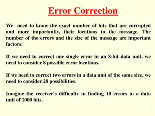
Data Error Detection Techniques Overview

Two-dimensional parity and Cyclic Redundancy Check (CRC) are data error detection methods used to ensure data integrity during transmission. Two-dimensional parity involves organizing bits in a table to calculate parity bits for data units and columns, while CRC appends a string of zeros to the data for division and error detection. Both techniques enhance error detection capabilities, though each has its limitations. Additionally, an introduction to Modular Arithmetic is provided, explaining the concept of modulo-N arithmetic for limited integer range operations.

Download Presentation

Please find below an Image/Link to download the presentation.
The content on the website is provided AS IS for your information and personal use only. It may not be sold, licensed, or shared on other websites without obtaining consent from the author. Download presentation by click this link. If you encounter any issues during the download, it is possible that the publisher has removed the file from their server.
E N D
Presentation Transcript
Two-Dimensional Parity -In this method, a block of bits is organized in a table (rows and columns). - First we calculate the parity bit for each data unit. Then we organize them into a table. Then we calculate the parity bit for each column and create a new row, these are the parity bits for the whole block.
Example 1 Suppose the following block is sent: 10101001 00111001 11011101 11100111 10101010 However, it is hit by a burst noise of length 8, and some bits are corrupted. 1010001110001001 11011101 11100111 10101010 When the receiver checks the parity bits, some of the bits do not follow the even-parity rule and the whole block is discarded. 10100011 10001001 11011101 11100111 10101010
Performance - Two-dimensional parity check increase the likelihood of detecting burst errors. - There is one pattern of errors that remain elusive. If 2 bits in one data unit are damaged and two bits in exactly the same positions in another data unit are also damaged, the checker will not detect an error.
Cyclic Redundancy Check (CRC) 1) A string of n 0s is appended to the end of the data unit. The number n is one less than the number of bits in the predetermined divisor, which is n+1 bits. 2) The newly elongated data unit is divided by the devisor using a process called binary division. The reminder resulting from this division is the CRC. 3) The CRC of n bits derived in step 2 replaces the appended 0s at the end of the data unit. If the derived remainder has fewer than n bits, the missing leftmost bits are presumed to be 0s. If the division process has not yielded a remainder at all then n 0s take the place of a remainder as the CRC (the original data is divisible by the deviser).
-The data unit arrives at the receiver data first, followed by the CRC. The receiver treats the whole string as a unit and divides it by the same divisor that was used to find the CRC remainder. - If the string arrives without error, the CRC checker yield a remainder of zero and the data unit passes. If the string has been changed in transit, the division yield a non-zero remainder and the data unit dose not pass.
Modular Arithmetic - In modular arithmetic, we use only a limited range of integers. We define an upper limit, called a modulus N. We then use only the integers 0 to N - 1. This is modulo-N arithmetic. For example, if the modulus is 12, we use only the integers 0 to 11 An example of modulo arithmetic is our clock system. It is based on modulo-12 arithmetic, substituting the number 12 for 0. If we start a job at 11 AM and the job takes 5 h, we can say that the job is to be finished at 16:00, or we can say that it will be finished at 4 P.M. (the remainder of 16/12 is 4). -Addition and subtraction in modulo arithmetic are simple. There is no carry when you add two digits in a column. There is no carry when you subtract one digit from another in a column. Modulo-2 Arithmetic We can use only 0 and 1. Operations in this arithmetic are very simple. The following shows how we can add or subtract 2 bits. (Like XOR Operation) Adding: 0+0=0 0+1=1 1+0=1 1+1=0 Subtracting: 0-0=0 0-1=1 1-0=1 1-1=0
The CRC Generator : It uses modulo-2 division
The CRC Checker : A CRC checker functions exactly as the generator dose. After receiving the data appended with the CRC. It dose the same modulo-2 division. If the remainder is all 0s the CRC is dropped and the data are accepted.
Polynomials The divisor in the CRC generator is most often represented not as a string of 1s and 0s, but as an algebraic polynomial . The Polynomial should be selected to have the following properties : -It should not be divided by x. -It should not be divided by x+1. The first condition guarantees that all burst errors of a length equal to the degree of the polynomial are detected. The second condition guarantees that all burst errors affecting an odd number of bits are detected.
The relationship of a polynomial to its corresponding binary (The devisor)
Standard polynomials Some standard polynomials used by popular protocols for CRC generation : ITU = International telecommunication Union The numbers 12,16 and 32 refer to the size of the CRC remainder. The CRC devisors are 13,17 and 33 bits respectively.
Performance 1- CRC can detect all burst errors that affect an odd number of bits. 2- CRC can detect all burst errors of length less than or equal to the degree of the polynomial. 3- CRC can detect, with a very high probability, burst errors of length greater than the degree of the polynomial.
Checksum This method of error detection is also based of the concept of redundancy. Sender
The Idea Suppose our data is a list of five 4-bit numbers that we want to send to a destination. In addition to sending these numbers, we send the sum of the numbers. For example, if the set of numbers is (7, 11, 12, 0, 6), we send (7, 11, 12,0,6,36), where 36 is the sum of the original numbers. The receiver adds the five numbers and compares the result with the sum. If the two are the same, the receiver assumes no error, accepts the five numbers, and discards the sum. Otherwise, there is an error somewhere and the data are not accepted. We can make the job of the receiver easier if we send the negative (complement) of the sum, called the checksum. In this case, we send (7, 11, 12,0,6, -36). The receiver can add all the numbers received (including the checksum). If the result is 0, it assumes no error; otherwise, there is an error.
The sender follows these steps: The unit is divided into k sections, each of n bits (usually 16). All sections are added using one s complement to get the sum in such way the total is also n bits long. The sum is complemented and becomes the checksum. The checksum is sent with the data.
The receiver follows these steps: The unit is divided into k sections, each of n bits. All sections are added using one s complement to get the sum. The sum is complemented. If the result is zero, the data are accepted: otherwise, rejected.
Example Suppose the following block of 16 bits is to be sent using a checksum of 8 bits. 10101001 00111001 The numbers are added using one s complement 10101001 00111001 ------------ Sum 11100010 Checksum 00011101 The pattern sent is 10101001 00111001 00011101
Now suppose the receiver receives the pattern sent in Example 7 and there is no error. 10101001 00111001 00011101 When the receiver adds the three sections, it will get all 1s, which, after complementing, is all 0s and shows that there is no error. 10101001 00111001 00011101 Sum 11111111 Complement 00000000 means that the pattern is OK.
Now suppose there is a burst error of length 5 that affects 4 bits. 1010111111111001 00011101 When the receiver adds the three sections, it gets 10101111 11111001 00011101 Partial Sum 1 11000101 Carry 1 Sum 11000110 Complement 00111001the pattern is corrupted.
Performance - The checksum detects all errors involving an odd number of bits as well as most errors involving as even number of bits. - If one or more bits of a segment are damaged and the corresponding bit or bits of opposite value in a second segment are also damaged, the sums of those columns will not change and the receiver will not detect a problem. - If the value of one word is incremented and the value of another word is decremented by the same amount, the two errors cannot be detected because the sum and checksum remain the same.


")