Understanding System of Limits, Fits, Tolerances, and Gauging
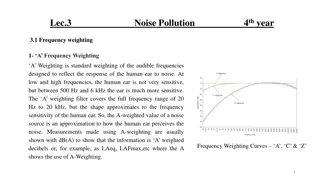
Tolerances play a crucial role in design processes by allowing for variations in dimensions during manufacturing. Types of tolerances include unilateral and bilateral, with accumulation and compound tolerances affecting overall variations. Terms related to metric limits and fits help define dimensions accurately. International Tolerance Grade (IT) ensures uniform accuracy across different sizes.

Download Presentation

Please find below an Image/Link to download the presentation.
The content on the website is provided AS IS for your information and personal use only. It may not be sold, licensed, or shared on other websites without obtaining consent from the author. Download presentation by click this link. If you encounter any issues during the download, it is possible that the publisher has removed the file from their server.
E N D
Presentation Transcript
UNIT II SYSTEM OF LIMITS, FITS, TOLERANCES AND GAUGING
TOLERANCES Tolerance is the total amount that a specific dimension is permitted to vary in positive or negative side It is the difference between the maximum and the minimum limits for the dimension. Due to the inevitable inaccuracy of manufacturing methods, a part cannot be made precisely to a given dimension. So tolerance is a mandatory thing in designing process of a component. TYPES OF TOLERANCES Unilateral tolerances Bilateral tolerances
UNILATERAL TOLERANCES Having variations in only one directions either upper or lower Limits are for only the larger or smaller sizes BILATERAL TOLERANCES Having variations in both the upper and lower directions The plus and minus limitations combine to form a single value.
ACCUMALATION TOLERANCES Tolerances are getting accumulated in each step of the components So, the total tolerance is the sum of the individual tolerance of each component. COMPOUND TOLERANCES Tolerance of one dimension of the component is dependent on the tolerance of the other dimension. That, if tolerance of one component increases the tolerance of the other increases or decreases.
TERMS RELATED TO METRIC LIMITS & FITS
Basic Size is the size from which limits or deviations are assigned. Basic sizes, usually diameters, should be selected from a table of preferred sizes. Nominal size is a dimension used to describe the general size Actual size is the measured size of the finished part after machining Limits is the max and min sizes shown by the toleranced dimension Allowance is the min clearance or maximum interference between parts, or the tightest fit between two mating parts Deviation: is the difference between the basic size and the hole or shaft size. Upper Deviation: is the difference between the basic size and the permitted maximum size of the part. Lower Deviation: is the difference between the basic size and the minimum permitted size of the part. Fundamental Deviation: is the deviation closest to the basic size. Tolerance: is the difference between the permitted minimum and maximum sizes of a part.
INTERNATIONAL TOLERANCE GRADE (IT): They are a set of tolerances that varies according to the basic size and provides a uniform level of accuracy within the grade.
SCHEMATIC REPRESENTATION OF THE PLACEMENT OF THE TOLERANCE INTERVAL E.S. upper deviation E.I. lower deviation H : lower deviation of hole is zero h : upper deviation of shaft is zero Formula for Fundamental deviation will be given separately
DEFINITION OF FITS Fit is the general term used to signify the range of tightness or looseness that may result from the application of a specific combination of allowances and tolerances in mating parts. TYPES OF FIT CLEARANCE FIT: an internal member fits in an external member (as a shaft in a hole) and always leaves a space or clearance between the parts. Minimum air space is 0.002 . This is the allowance and is always positive in a clearance fit
INTERFERENCE FIT: The internal member is larger than the external member such that there is always an actual interference of material. The smallest shaft is 1.2513 and the largest hole is 1.2506 , so that there is an actual interference of metal amounting to at least 0.0007 . Under maximum material conditions the interference would be 0.0019 . This interference is the allowance, and in an interference fit it is always negative. TRANSITION FIT: may result in either a clearance or interference condition. In the figure below, the smallest shaft 1.2503 will fit in the largest hole 1.2506 , with 0.003 to spare. But the largest shaft, 1.2509 will have to be forced into the smallest hole, 1.2500 with an interference of metal of 0.009 .
SYSTEM OF FITS BASIC SHAFT SYSTEM the largest diameter of the shaft is assigned the basic diameter from which all tolerances are applied. The fundamental deviation is given by the lowercase letter h. BASIC HOLE SYSTEM the smallest hole is assigned the basic diameter from which the tolerance and allowance are applied. (more popular than the basic shaft system because of ease to control the hole size) For the generally preferred hole-basis system, the fundamental deviation is specified by the upper-case letter H.
PLAIN GAUGES PLAIN PLUG GAUGES Used for checking inside diameter of straight hole (generally "go" and "no-go" variety) Consists of handle and plug on each end ground and/or lapped to specific size Small-diameter plug ("go" gage) checks lower limit of hole Larger-diameter plug ( no-go gage) checks upper limit PLAIN RING GAGES Used to check outside diameter of pieces Ground and lapped internally to desired size Size stamped on side of gage Outside diameter knurled and "no-go" end identified by annular groove on knurled surface Precautions and procedures similar to those outlined for a plug gage
SNAP GAGES One of most common types of comparative measuring instruments Faster to use than micrometers Limited in their application Used to check diameters within certain limits by comparing part size to preset dimension of snap gage Have C-shaped frame with adjustable gaging anvils or rolls set to "go" and "no-go" limits of the part


:")