Challenges and Tolerances for Compact Hybrid Ultrafast X-ray Pulse Source
A study on challenges and tolerances for a compact hybrid ultrafast X-ray pulse source based on RF and THz technologies was presented at EACC 2019. The research, funded by the European Research Council and Laserlab-Europe, focused on creating ultrafast X-ray pulses using S-band RF-gun, THz linac, Quadrupole triplet, and collision with a ps laser. Detailed simulations were conducted on e-bunch and X-ray properties for efficient beam dynamics and X-ray generation via ICS.

Download Presentation

Please find below an Image/Link to download the presentation.
The content on the website is provided AS IS for your information and personal use only. It may not be sold, licensed, or shared on other websites without obtaining consent from the author. Download presentation by click this link. If you encounter any issues during the download, it is possible that the publisher has removed the file from their server.
E N D
Presentation Transcript
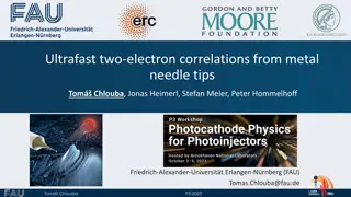
Challenges and tolerances for a compact and hybrid ultrafast X-ray pulse source based on RF and THz technologies Thomas Vinatier, Ralph Assmann, Ulrich Dorda, Fran ois Lemery, Barbara Marchetti, DESY, Hamburg, Germany EAAC 2019, Wednesday 18thSeptember 2019, Working group 3 The authors would like to thank K. Fl ttmann and the entire AXSIS collaboration for fruitful discussions The research leading to these results has received funding from the European Research Council under the European Union s Seventh Framework Programme (FP/2007-2013) ERC Grant Agreement n. 609920, and by the Laserlab-Europe Grant Agreement n. 654148.
Outline > Introduction > Tolerance study > Other challenges > Conclusions
Outline: Introduction > Introduction Presentation of the concept Simulation of e- bunch properties Simulation of X-ray properties > Tolerance study > Other challenges > Conclusions
Presentation of the hybrid concept > S-band RF-gun: 6 MeV e- bunch with 0.1 to a few pC charge. > THz linac (THz-driven dielectric-loaded waveguide): Acceleration to 15-20 MeV & compression to the single femtosecond order or below. > Quadrupole triplet: Transverse focusing to below 10 m rms. > Collision with ps laser: 3 to 12 keV ultrafast X-ray pulses via ICS. ps IR laser (400 mJ) Details in T. Vinatier et al., Nucl. Instr. Meth. A 909, p. 185 (2018) & T. Vinatier et al., J. Appl. Phys. 125, 164901 (2019)
Simulation of e- bunch properties > Start-to-end beam dynamics simulations, up to the ICS point, performed with ASTRA for two frequencies in the THz linac (150 and 300 GHz). Typical properties at the ICS point for f = 300 GHz (115 MV/m) and a 1 mm vacuum diameter Q (pC) <E> (MeV) 17.7 17.5 17.6 E(keV) t(fs) x* y( m2) 4.5*5.9 6.8*7.9 8.9*9.7 x* y( m2) 0.11*0.11 0.23*0.19 0.32*0.24 0.1 1 2 42 130 190 0.4 1.3 1.9 Typical properties at the ICS point for f = 150 GHz (115 MV/m) and a 2 mm vacuum diameter Q (pC) <E> (MeV) 15.0 15.0 E(keV) t(fs) x* y( m2) 6.0*6.2 8.7*8.6 x* y( m2) 0.21*0.19 0.38*0.29 1 4 45 130 1.8 3.1 Details in T. Vinatier et al., Nucl. Instr. Meth. A 909, p. 185 (2018) & T. Vinatier et al., J. Appl. Phys. 125, 164901 (2019)
Simulation of X-ray properties > Simulation of the X-ray generation via ICS simulated with the Monte-Carlo code CAIN for two laser wavelengths (1048 and 524 nm) and 1 ps rms length. coll= 4 mrad / = 1.5% EX: Mean X-ray energy; coll: Collimation angle; N , coll: Number of collimated photons/shot; / : rms bandwidth Details in T. Vinatier et al., J. Appl. Phys. 125, 164901 (2019)
Outline: Tolerance study > Introduction > Tolerance study Approach and tools RF-gun, solenoid and UV laser jitters THz linac field amplitude and phase jitters THz linac misalignments Quadrupoles gradients jitters Quadrupoles misalignments ICS laser imperfections and misalignments > Other challenges > Conclusions
Approach and tools > Tolerance study performed with ASTRA parameter scanning and a self-written Matlab code (influence of a single imperfection/jitter) and with the ERROR namelist of ASTRA (simultaneous influence of several imperfections/jitters). Field amplitude & phase jitters Gradients jitter Field amplitude & phase jitters Amplitude jitter Energy & pointing jitters 3D translation (x,y,z) & 2D rotation (x,y) 3D translation (x,y,z) & 3D rotation (x,y,z) Waist & duration Transverse offset Timing jitter Pointing jitter and arrival timing jitter at the THz linac entrance > Not all results shown in this talk, only those most affecting the e-bunch properties.
RF-gun, solenoid and UV laser jitters Reference electron bunch properties at the ICS point Q (pC) <E> (MeV) E(keV) 123 t(fs) 1.31 x* y( m2) 10.6*10.5 x* y( m2) 0.226*0.189 1 17.65 RF-gun: 0.01% rms peak field jitter & 0.006 ( 5.5 fs at 3 GHz) rms laser/RF-field phase jitter assumed. UV laser: 35 m rms pointing jitter & 3% energy jitter assumed. Solenoid: 0.04% rms peak field jitter assumed. > > > Simultaneous study of all the jitters show that tand especially Eare the most affected properties. tvariation under the assumed jitters Evariation under the assumed jitters > The assumed jitters, at the state-of-the-art for the RF-gun, are needed to keep the longitudinal properties under control, although not totally satisfactorily for E. Decoupling all the jitters is needed to determine which one has the strongest influence and if it can be improved.
THz linac field amplitude and phase jitters Reference electron bunch properties at the ICS point (f = 300 GHz) Q (pC) <E> (MeV) E(keV) 123 t(fs) 1.31 x* y( m2) 10.6*10.5 x* y( m2) 0.226*0.189 1 17.65 Phase: 1 rms jitter assumed. Especially affects bunch length ( t), energy spread ( E) and mean energy (<E>). Field amplitude: 1% rms jitter assumed. Especially affects t, Eand the bunch transverse size ( xand y). > > Evariation under a 1 rms phase jitter yvariation under 1% rms amplitude jitter > A 1% rms amplitude jitter looks reasonable for the stability of the e-bunch properties. On the opposite, the phase jitter would have to be reduced significantly below 1 .
THz linac misalignments y Reference electron bunch properties at the ICS point z Q (pC) <E> (MeV) E(keV) 123 t(fs) 1.31 x* y( m2) 10.6*10.5 x* y( m2) 0.226*0.189 x 1 17.65 Offsets: x and y up to +/- 0.6 mm. z up to +/- 1 mm. A y offset affects Eand t. Rotations: around x and y up to 9 mrad ( 0.52 ) w.r.t. linac entrance and 13 mrad ( 0.75 ) w.r.t. linac center. All rotations affects Eand t. A rotation around x (y) strongly affects x( y) and x( y). > > Charge losses vs rotation angle Eand tvariations vs rotation around y w.r.t. linac center yand yvariations vs rotation around y w.r.t. linac entrance > Transverse offset should be kept below 200 m and rotations below 1 mrad. > This is well within the theoretical accuracy of positioning devices (e.g. hexapodes). However, the practical accuracy rely on a beam-based alignement procedure and has to be determined.
Quadrupoles gradients jitters Reference electron bunch properties at the ICS point Q (pC) <E> (MeV) E(keV) 123 t(fs) 1.31 x* y( m2) 10.6*10.5 x* y( m2) 0.226*0.189 1 17.65 Gradient detuning studied independently for the 3 quadrupoles up to around +/- 2%. Bunch properties more affected by a detuning of the 2nd quadrupole. xand especially yare the most affected properties. Simultaneous jitter of 0.5% rms for all the gradients also studied. > > yvariation vs gradient detuning of the quadrupoles yvariation under a 0.5% rms gradient jitter > Keeping the gradient jitter of the 2ndquadrupole below 0.5% (reasonable) would allow to keep the e-bunch properties variation below 15% (max. for y).
Quadrupoles misalignments y Reference electron bunch properties at the ICS point z Q (pC) <E> (MeV) E(keV) 123 t(fs) 1.31 x* y( m2) 10.6*10.5 x* y( m2) 0.226*0.189 x 1 17.65 Offsets: x and y up to +/- 0.5 mm. z up to +/- 1 mm. A y offset of the 3rdand especially 2ndquadrupoles affects E, t, yand y. Rotations: around x, y and z up to 20 mrad ( 1.15 ). A rotation around z of the 2nd(1st) quadrupole affects x( y) and x( y). > > yvariation vs rotation around z (skew) tvariation vs offset along y > Quadrupole rotation around z (skew) should be kept below 0.5 (9 mrad) (reasonable) and y offset below 100 m for the 2ndquadrupole (more challenging).
ICS laser imperfections and misalignments Reference X-ray pulse properties at the ICS point EX(keV) 5.9 N , coll 2*104 SPD (ph/eV) Case coll(mrad) 4 / (%) 1.4 Laser rat focus ( m) 10.5 Laser t(ps) 1 90 1 2 4.3 4 4*104 1.1 300 6.1 1 EX: Mean X-ray energy; coll: Collimation angle; N , coll: Number of collimated photons/shot; / : rms bandwidth; SPD: Spectral photon density number of photons/eV within the rms bandwidth (figur of merit) Transverse misalignment studied up to 3 rof the laser at focus. Time offset with the e-bunch studied up to 10 t( 10 ps) of the laser. > N , collvariation vs transverse misalignment N , collvariation vs time offset > Synchronization with the ICS laser at the ps level required (reasonable). Transverse alignment e-bunch/ICS laser of a few m required (study of e-bunch pointing jitter is ongoing).
Outline: Other challenges > Introduction > Tolerance study > Other challenges THz requirements and generation Dielectric-loaded waveguide manufacturing > Conclusions
THz requirements and generation > Quartz dielectric loading assumed ( r= 4.41). > vph & vg : THz pulse phase & group velocities. > T: THz pulse duration; > <P> & ETHz : THz pulse average peak power & energy. f (GHz) 300 150 150 a ( m) 500 1000 800 b a ( m) 90.35 180.71 201.53 vph(c-1) 1 1 1 vg(c-1) 0.5132 0.5132 0.4143 T (ps) 407 407 607 <P> (MW) 23.3 93.9 47.4 ETHz(mJ) 9.5 38.2 28.8 > None of the schemes studied for THz generation (laser-based, gyrotrons, CSR/FEL, wakefields) is currently able to fulfil all these requirements at once. > Research ongoing on efficient laser-based THz generation in non-linear crystals shows THz power (close to) fulfiling the requirement in short pulses ( 10% T). Research still has to be done to produce longer pulses.
Dielectric-loaded waveguide manufacturing > Requirement from beam dynamics simulations: Control of the phase velocity at a level better than 1 . > Problem: This requires a very tight manufacturing accuracy for the waveguide (dielectric thickness accuracy better than 150 nm). Phase velocity as a function of the dielectric thickness variation for f = 300 GHz, a = 500 m and r= 4.4 > Solution: Adjustment of vphby tuning the frequency of the THz field (feasible by tuning the temperature of the non-linear crystal in the case of laser-generated THz) could compensate waveguide production errors. 1 control level on vphcorresponds roughly to 1 K control level on the crystal temperature. Temperature dependent ? ? = (???? ??????) nTHz& nlaser: refractive indices for THz/laser in the crystal. : Crystal poling period Phase velocity as a function of the frequency variation for a = 500 m, b a = 90.4 m and r= 4.4
Outline: Conclusions > Introduction > Tolerance study > Other challenges > Conclusions
Conclusions > A tolerance study has been performed (and is continued) to determine what are the requirements in terms of jitters and misalignments for an ICS-based compact ultrafast X-ray pulse source mixing RF (gun) and THz (linac) technologies. Some of them were found to be particularly challenging or still to be investigated. Offset < 200 m & rotation < 1 mrad (dependent on beam- based alignment). At least: 0.01% peak field jitter & 0.006 phase jitter ( 5.5 fs) ( state-of-the-art). Offset < 100 m. Transverse misalignment e-bunch/ICS laser few m (e-bunch pointing jitter study ongoing). 1% peak field jitter & < 1 phase jitter. Dependent on THz source (e.g. laser). To be studied. Phase velocity fine-tuning THz requirements