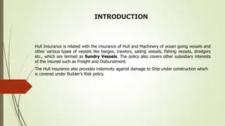
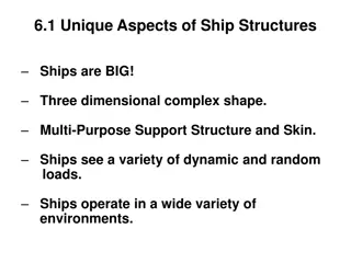
Understanding Ship Drive Train and Power Systems
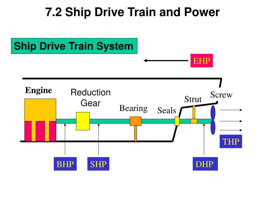
Ship drive train and power systems play a crucial role in the propulsion of ships. Components like engines, reduction gears, screws, bearings, and seals work together to convert engine power into thrust horsepower (THP) that drives the propeller. Various types of horsepowers like effective horsepower (EHP), brake horsepower (BHP), shaft horsepower (SHP), delivered horsepower (DHP), and thrust horsepower (THP) are involved in the system. The relationship between these power magnitudes is important, with BHP being greater than SHP, DHP, THP, and EHP due to inevitable power losses from factors like heat, friction, and sound. Effective horsepower (EHP) is specifically related to the power required to move the ship hull at a given speed. Experimental methods like towing tank tests help determine EHP, which can be extrapolated to full-scale ships using Froude's Law.

Download Presentation

Please find below an Image/Link to download the presentation.
The content on the website is provided AS IS for your information and personal use only. It may not be sold, licensed, or shared on other websites without obtaining consent from the author. Download presentation by click this link. If you encounter any issues during the download, it is possible that the publisher has removed the file from their server.
E N D
Presentation Transcript
7.2 Ship Drive Train and Power Ship Drive Train System EHP Engine Reduction Gear Screw Strut Bearing Seals THP BHP SHP DHP
Ship Drive Train and Power EHP Engine Strut Reduction Gear Screw Bearing Seals THP DHP BHP SHP Brake Horsepower (BHP) - Power output at the shaft coming out of the engine before the reduction gears
Ship Drive Train and Power EHP Engine Strut Reduction Gear Screw Bearing Seals THP DHP BHP SHP Shaft Horsepower (SHP) - Power output at the shaft coming out of the reduction gears
Ship Drive Train and Power EHP Engine Strut Reduction Gear Screw Bearing Seals THP BHP DHP SHP Delivered Horsepower (DHP) - Power delivered to the propeller - DHP=SHP losses in shafting, shaft bearings and seals
Ship Drive Train and Power EHP Engine Strut Reduction Gear Screw Bearing Seals THP DHP BHP SHP Thrust Horsepower (THP) - Power created by the screw/propeller - THP=DHP Propeller losses - THP is the end result of all HP losses along the drive train
Ship Drive Train and Power EHP BHP SHP DHP THP Shaft Bearing Hull E/G R/G Prop. Relative Magnitudes BHP> SHP > DHP > THP > EHP The reverse relationship can NEVER be true because there is ALWAYS some loss of power due to heat, friction, and sound
7.3 Effective Horsepower (EHP) The power required to move the ship hull at a given speed in the absence of propeller action EHP is not related to Power Train System EHP can be determined from the towing tank experiments at the various speeds of the model ship EHP of the model ship is converted into EHP of the full scale ship by Froude s Law. Measured EHP V Towing carriage Towing Tank
Effective Horsepower (EHP) POWER CURVE YARD PATROL CRAFT Typical EHP Curve of YP 1000 Effective Horsepower, EHP (HP) 800 600 400 200 0 0 2 4 6 8 10 12 14 16 Ship Speed, Vs (Knots) The required EHP varies depending on the vessel s speed.
Effective Horsepower (EHP) EHP Calculation ft R (lb) V T S s = EHP(H ) = resistance hull total R P T ft lb S= 550 V speed of ship s H P ft lb ft J ( ) lb V = = = Power : R Watts T S s s s / 1 = 1 W 550 H atts P
7.4 Propulsion Efficiency The loss in HP along the drive train can be related in terms of EFFICIENCY, or Gear Efficiency gear = SHP BHP Shaft Horsepower Brake Horsepower -Highlights the loss of horsepower from the engine to the shaft as a result of the reduction gears - SHP is always less than BHP
Propulsion Efficiency Shaft Transmission Efficiency shaft = DHP SHP Delivered Horsepower Shaft Horsepower - The loss of horsepower from the reduction gears to the propeller due to the bearings and seals that support and seal the drive shaft - The loss of power is converted to heat and sound due to friction
Propulsion Efficiency Hull Efficiency (The loss of power will be a function of the hull design) EHP Effective Horsepower Thrust Horsepower H= THP - Hull efficiency changes due to hull-propeller interactions. - Well-designed ship : - Poorly-designed ship : H 1 H 1 Well-designed - Flow is not smooth. - THP is reduced. - High THP is needed to get designed speed. Poorly-designed
Propulsion Efficiency EHP Propeller Efficiency Screw THP propeller= DHP THP SHP DHP
Propulsion Efficiency Propulsive Efficiency (Coefficient (PC)) P = EHP SHP Effective Horsepower Shaft Horsepower - Combines the losses due to the bearings, guides, and the propeller efficiency -Compares the output from the reduction gears to the required towing HP -Commonly ranges from 55 - 75% -Once p is found, can try different power plants, gearing, and fuel efficiencies
Example: Through modeling of a ship s design, it is found that the towing horsepower required to maintain a speed of 20 knots is 23,500 HP. Assuming a propulsive efficiency of 68%, what is the expected required power output from the reduction gears (shaft horsepower)? Solution: P = EHP SHP .68 = 23,500 HP SHP SHP = 23,500 HP / .68 SHP = 34,559 HP
Example Problem What are the various components, HPs, s and common values for s for the drawing below? _HP _HP _HP _HP _HP gear=_HP/_HP (~__-__%) shaft=_HP/_HP (~__-__%) prop=_HP/_HP (~__-__%) H=_HP/_HP P=PC=_HP/_HP (~__-__%)
Example Answer What are the various components, HPs, s and common values for s for the drawing below? BHP SHP DHP EHP THP Prime Mover Reduction Gear Shafting & Bearings Propeller Hull gear=SHP/BHP (~98-99%) shaft=DHP/SHP (~97-98%) prop=THP/DHP (~70-75%) H=EHP/THP P=PC=EHP/SHP (~55-75%)
7.5 Total Hull Resistance Total Hull Resistance (RT) The force that the ship experiences opposite to the motion of the ship as it moves. EHP Calculation ft R (lb) V = total hull resistance R T S s T = EHP(H ) S= V speed of ship P ft lb 550 s H P
Total Hull Resistance Coefficient of Total Hull Resistance - Non-dimensional value of total resistance R lb = C T non - dimension 2 T 2S 5 . 0 V 2 lb s ft 2 ft s 4 ft s = Coefficien t of resistance hull total calm in water C T resistance hull Total = R T = Fluid = density Speed of ship V S = submerged the on area surface wetted hull S
Total Hull Resistance Coefficient of Total Hull Resistance -Total Resistance of full scale ship can be determined using V S C , , and T S 2 = ( ) 5 . 0 R lb SV C T S T determined model the by test : C T available : S from water property table obtained : from Curves of form : Full scale ship speed V S
Total Hull Resistance Relation of Total Resistance Coefficient and Speed TOTAL RESISTANCE CURVE YARD PATROL CRAFT 20000 Total Resistance, Rt (lb) 15000 10000 5000 0 0 2 4 6 8 10 12 14 16 Ship Speed, Vs (knots) 2 2 R C V EHP R V C V V T T S T S T S S n n n n V V S S from = = 2 at low speed from 3 at low speed t high at 5 o speed high at 6 to speed
7.6 Total Hull Resistance Resistance values, denoted by R, are dimensional values RT = Total hull resistance is the sum of all resistance RT = RAA + RW + RV Air Resistance Wave Making Resistance Viscous Resistance RAA = Resistance caused by calm air on the superstructure RW = Resistance due to waves caused by the ship - A function of beam to length ratio, displacement, hull shape & Froude number (ship length & speed) RV = Viscous resistance (frictional resistance of water) - A function of viscosity of water, speed, and wetted surface area of ship For pilots, this is subsonic, incompressible drag
Total Hull Resistance Total Resistance and Relative Magnitude of Components Air Resistance Hollow Wave-making Hump Viscous Speed (kts) - Low speed : Viscous R - Higher speed : Wave-making R - Hump (Hollow) : location is function of ship length and speed.
Components of Total Resistance Viscous Resistance - Resistance due to the viscous stresses that the fluid exerts on the hull. ( due to friction of the water against the surface of the ship) - Viscosity, ship s velocity, wetted surface area of ship generally affect the viscous resistance. Wave-Making Resistance - Resistance caused by waves generated by the motion of the ship - Wave-making resistance is affected by beam to length ratio, displacement, shape of hull, Froude number (ship length & speed) Air Resistance - Resistance caused by the flow of air over the ship with no wind present - Air resistance is affected by projected area, shape of the ship above the water line, wind velocity and direction - Typically 4 ~ 8 % of the total resistance
Components of Total Resistance Dimensionless Coefficients CT = Coefficient of total hull resistance CT = CV + CW CV = Coefficient of viscous resistance over the wetted area of the ship as it moves through the water - CF = Tangential component (skin resistance) - KCF = Normal component (viscous pressure drag) CW = Coefficient of wave-making resistance
Coefficient of Viscous Resistance (CV) Viscous Flow around a ship Real ship : Turbulent flow exists near the bow. Model ship : Studs or sand strips are attached at the bow to create the turbulent flow.
Coefficient of Viscous Resistance (CV) Coefficients of Viscous Resistance - Non-dimensional quantity of viscous resistance - It consists of tangential and normal components. CF=tangential (skin friction) component of viscous resistance KCF=normal (viscous pressure/form drag) component of viscous friction + = tangential V C C C = C + KC normal F F flow ship stern bow Tangential Component : CF - Tangential stress is parallel to ship s hull and causes a net force opposing the motion ; Skin Friction - It is assumed can be obtained from the experimental data of flat plate. C F
Coefficient of Viscous Resistance (CV) = Tangential Component of C C V F . 0 075 = C Semi-empirical equation F 2 (log ) 2 R 10 n LV = R S n = Reynolds Number R n = L = (ft) L pp Speed(ft/s Ship ) V S = 2 Kinematic Viscosity (ft /s) = 5 - 2 1.2260 10 ft /s for fresh water = 5 - 2 1.2791 10 ft /s for salt water
Coefficient of Viscous Resistance (CV) Boundary Layer Separation Resistance Bernoulli s Equation: p/ +V /2+gz=constant Viscous Pressure/Form Drag Laminar Flow High Velocity/ Low Pressure Low Velocity/ High Pressure Low Velocity/ High Pressure Turbulent Flow Boundary Layer High Velocity/ Low Pressure Boundary Layer Separation Boundary Layer Low Velocity/ High Pressure Turbulent Wake
Coefficient of Viscous Resistance (CV) Tangential Component: CF - Relation between viscous flow and Reynolds number Laminar flow : In laminar flow, the fluid flows in layers in an orderly fashion. The layers do not mix transversely but slide over one another. Turbulent flow : In turbulent flow, the flow is chaotic and mixed transversely. Flow over flat plate Laminar Flow Turbulent Flow about Rn 5 5 10 about 5 5 Rn 10
Coefficient of Viscous Resistance (CV) Normal Component: KCF - Normal component causes a pressure distribution along the underwater hull form of ship - A high pressure is formed in the forward direction opposing the motion and a lower pressure is formed aft. - Normal component generates the eddy behind the hull. - It is affected by hull shape. Fuller shape ship has larger normal component than slender ship. large eddy Full ship Slender ship small eddy
Coefficient of Viscous Resistance (CV) Normal Component: KCF - It is calculated by the product of Skin Friction with Form Factor. = Normal Component of C K C v F = Skin Friction Coeff. C F = Form Factor K 2 B 3 (ft ) ( ) B ft 19 = K ( ) ( ) ( ) ( ) L ft ft T ft L ft
Coefficient of Viscous Resistance (CV) = + = C + K C C tangential C . 0 C F F V normal 075 R 2 B 3 (ft ) ( ) B ft = C 19 = K F 2 (log ) 2 ( ) ( ) ( ) ( ) L ft ft T ft L ft 10 n LV = K= Form Factor R S n = Reynolds Number R n = L = (ft) L pp Speed(ft/s Ship ) V S = 2 Kinematic = Viscosity (ft /s) 5 - 2 1.2260 10 ft /s for fresh water = 5 - 2 1.2791 10 ft /s for salt water
Coefficient of Viscous Resistance (CV) Reducing the Viscous Resistance Coeff. - Method : Increase L while keeping the submerged volume constant 1) Form Factor K Normal component KCF Slender hull is favorable. ( Slender hull form will create a smaller pressure difference between bow and stern.) 2) Reynolds No. Rn CF KCF
Froude Number Fn The Froude Number (inertia force/gravity force) is another dimensionless value derived from model testing: Fn = V \/gL Also used, but not dimensionless, is the Speed-to-Length Ratio: Speed-to-Length Ratio = V \/L ...Velocity is typically expressed in Knots (1 knot = 1.688ft/s)
Coefficient of Wave Resistance CW Typical Wave Patterns are made up of TRANSVERSE and DIVERGENT waves Stern divergent wave Bow divergent wave Bow divergent wave L Transverse wave Wave Length
Coefficient of Wave Resistance CW Transverse wave System It travels at approximately the same speed as the ship. At slow speed, several crests exist along the ship length because the wave lengths are smaller than the ship length. As the ship speeds up, the length of the transverse wave increases. When the transverse wave length approaches the ship length, the wave making resistance increases very rapidly. This is the main reason for the dramatic increase in Total Resistance as speed increases.
Coefficient of Wave Resistance CW Transverse wave System Vs < Hull Speed Slow Speed Wave Length Vs Hull Speed High Speed Wave Length Hull Speed : speed at which the transverse wave length equals the ship length. (Wavemaking resistance drastically increases above hull speed)
Coefficient of Wave Resistance CW Divergent Wave System It consists of Bow and Stern Waves. Interaction of the bow and stern waves create the Hollow or Hump on the resistance curve. Hump : When the bow and stern waves are in phase, the crests are added up so that larger divergent wave systems are generated. Hollow : When the bow and stern waves are out of phase, the crests matches the trough so that smaller divergent wave systems are generated.
Coefficient of Wave Resistance CW Air Resistance Hollow Wave-making Hump Viscous Speed (kts) - Low speed : Viscous R - Higher speed : Wave-making R - Hump (Hollow) : location is function of ship length and speed.
Coefficient of Wave Resistance CW Calculation of Wave-Making Resistance Coeff. Wave-making resistance is affected by - beam to length ratio - displacement - hull shape - Froude number The calculation of the coefficient is far difficult and inaccurate from any theoretical or empirical equation. (Because mathematical modeling of the flow around ship is very complex since there exists fluid-air boundary, wave-body interaction) Therefore model test in the towing tank and Froude expansion are needed to calculate the Cw of the real ship.
Coefficient of Wave Resistance CW It takes energy to produce waves, and as speed increases, the energy required is a square function of velocity! Lwave = 2 V2 g The limiting speed, or hull speed, can be found as: V = 1.34\/Ls Note: Remember at the hull speed, Lwave and Ls are approximately equal!
Coefficient of Wave Resistance CW Reducing Wave Making Resistance 1) Increasing ship length to reduce the transverse wave - Hull speed will increase. - Therefore increment of wave-making resistance of longer ship will be small until the ship reaches to the hull speed. - EX : FFG7 : ship length 408 ft hull speed 27 KTS CVN65 : ship length 1040 ft hull speed 43 KTS
Coefficient of Wave Resistance CW Reducing Wave Making Resistance 2) Attaching Bulbous Bow to reduce the bow divergent wave - Bulbous bow generates the second bow waves . - Then the waves interact with the bow wave resulting in ideally no waves, practically smaller bow divergent waves. - EX : DDG 51 : 7 % reduction in fuel consumption at cruise speed 3% reduction at max speed. design &retrofit cost : less than $30 million life cycle fuel cost saving for all the ship : $250 mil. Tankers & Containers : adopting the Bulbous bow
Coefficient of Wave Resistance CW Bulbous Bow
Coefficient of Total Resistance Coefficient of total hull resistance = + + C C = C C + T V W + A + 1 C ( K) C C F W A Correlatio : A Allowance n C Correlation Allowance It accounts for hull resistance due to surface roughness, paint roughness, corrosion, and fouling of the hull surface. It is only used when a full-scale ship prediction of EHP is made from model test results. For model, For ship, empirical formulas can be used. = Since model surface smooth is 0 . C A
Other Type of Resistances Appendage Resistance - Frictional resistance caused by the underwater appendages such as rudder, propeller shaft, bilge keels and struts - 2 24% of the total resistance in naval ship. Steering Resistance - Resistance caused by the rudder motion. - Small in warships but troublesome in sail boats Added Resistance - Resistance due to sea waves which will cause the ship motions (pitching, rolling, heaving, yawing).
Other Type of Resistances Increased Resistance in Shallow Water - Resistance caused by shallow water effect - Flow velocities under the hull increases in shallow water. Increase of frictional resistance due to the velocities Pressure drop, suction, increase of wetted surface area Increases frictional resistance - The waves created in shallow water take more energy from the ship than they do in deep water for the same speed. Increases wave making resistance
Operating to Minimize Resistance Keep the hull clean Operate at a prudent speed Keep speed below hump speed to optimize economy


")
")
")


")
")
")
")
")
")
")
")
")