Wireless Network Essentials and Classification
21. Wireless Internet
General wireless network issues
WiFi
»
channels and association
»
CSMA/CA
»
packet header fields
Roch Guerin
(with adaptations from Jon Turner and John DeHart, and
material from Kurose and Ross)
Wireless and Mobile Networks
Background:
»
# wireless (mobile) phone subscribers now far exceed # wired
phone subscribers
»
# wireless Internet-connected devices surpasses # wired
Internet-connected devices
•
laptops, Internet-enabled phones promise anytime untethered
Internet access
•
Internet-of-Things will give this yet another boost
two important (but different) challenges
»
wireless:
communication over wireless link
»
mobility:
handling the mobile user who changes point of
attachment to network
CSE574: Wireless and Mobile Networking
2
Elements of a Wireless Network
wireless hosts
-
laptop, phone
-
run apps
-
may be mobile or
stationary
base stations
-
typically connected to
wired network
-
relay - responsible for
sending packets between
wired network and wireless
host(s) in its “area”
-
e.g., cell towers, 802.11
access points
wireless links
-
typically used to connect
mobile(s) to base station
-
also used as backbone link
-
multiple access protocol
coordinates link access
-
various data rates,
transmission distance
3
Characteristics of Wireless Links
Indoor
10-30m
Outdoor
50-200m
Mid-range
outdoor
200m – 4 Km
Long-range
outdoor
5Km – 20 Km
.056
.384
1
4
5-11
54
2
G
:
I
S
-
9
5
,
C
D
M
A
,
G
S
M
2
.
5
G
:
U
M
T
S
/
W
C
D
M
A
,
C
D
M
A
2
0
0
0
8
0
2
.
1
5
3
G
:
U
M
T
S
/
W
C
D
M
A
-
H
S
P
D
A
,
C
D
M
A
2
0
0
0
-
1
x
E
V
D
O
4
G
:
L
T
W
E
W
I
M
A
X
8
0
2
.
1
1
a
,
g
p
o
i
n
t
-
t
o
-
p
o
i
n
t
200
8
0
2
.
1
1
n
Data rate (Mbps)
4
5
G
(
2
0
2
0
)
8
0
2
.
1
1
b
8
0
2
.
1
1
a
,
g
Ad hoc Operation
No base stations or
“infrastructure nodes”
Nodes can only transmit to
others within range
Nodes organize and among
themselves
»
Notice each other
»
Find they have something to share
»
Cooperate to form “network” and
forward packets
5
Wireless Network Classification
6
7
IEEE 802.11 LAN Standards
8
IEEE 802.11 LAN Standards
My office:
netsh wlan show interfaces
»
Shows that my laptop connects over 802.11n with
a speed that seems to vary between 270Mbps and
300Mbps
Basics of Spreading Gain
Sender transmits
»
S
= 1
B
»
S
= 0
-B
Interference, say,
continuously
transmits
J
Receiver gets
(
S
+
J
)
and computes
(
S
+
J
)
B=
S
B+
J
B
»
B
B = +11
»
-B
B = -11
»
J
B = +1
Computation yields
»
S
= 1
B
(
S
+
J
)
B = +12
1
»
S
= 0
-B
(
S
+
J
)
B = -10
0
9
Wireless Link Characteristics
Differences from wired links
»
decreased signal strength:
radio signal attenuates as it propagates
(path loss) – much faster than when guided through wire
»
interference from other sources:
standardized wireless network
frequencies (
e.g.,
2.4 GHz) shared by other devices (
e.g.,
wireless
phones, electric motors, microwave ovens)
»
multipath propagation:
radio signal reflects off objects and ground,
arriving at destination at slightly different times
Makes communication across (even point-to-point) wireless
link more
challenging
»
Lower and variable achievable bit rates
»
higher error rates
»
limited distances without sophisticated antennas(beam-forming)
•
On the flip side, this ensures limited propagation delays
»
more vulnerable to snooping (signal is inherently broadcast)
•
Stronger need for encryption
10
Wireless Link Characteristics
SNR: signal-to-noise ratio
»
larger SNR is good
•
easier to separate signal from noise
»
measured in decibels (db)
•
logarithmic scale – increase of
3 db corresponds to doubling ratio
SNR versus BER tradeoffs
»
signal power
•
increased power leads to higher
SNR and lower BER
»
alternate modulation schemes
•
more sophisticated methods yield
higher data rate, but also higher BER
•
can sometimes select modulation
technique based on conditions
11
Wireless Network Characteristics
Multiple wireless senders and receivers create
additional problems (beyond multiple access):
Hidden terminal problem
»
A
,
B
hear each other,
B
,
C
hear each other
»
A
,
C
cannot hear each other, so may send simultaneously
causing interference at
B. A, C
cannot detect collision
»
can be caused by obstacle or signal attenuation over distance
12
13
A transmits frame
(a)
Data Frame
A
B
Frames from A & B
collide at C
(b)
B senses clear medium;
A
hidden
from B
Data Frame
B
A
Hidden Terminal Problem
Hearing No One Does Not Mean I Can Transmit
C
C
Data Frame
14
B
C
A
Exposed Node Problem
Hearing Someone Does Not Mean I Cannot Transmit
D
B
C
A
D
B hears C and thinks
that C’s transmissions
preclude talking to D
But B can talk to D
without interfering with
C’s transmissions to A
802.11 LAN Architecture
Wireless host
communicates with
access point (AP)
Wireless subnet called
Basic Service Set (BSS)
»
in infrastructure mode
contains wireless hosts and
access point (AP)
»
in ad hoc mode, just hosts
15
802.11: Channels
802.11b: 2.4GHz-2.5 GHz spectrum (unlicensed)
divided into 11 channels with overlapping frequencies
»
AP administrator chooses frequency for AP
•
interference possible: channel can be same as that chosen by
neighboring AP (or may overlap)
16
802.11: Association
Host: must
associate
with an AP
»
scans channels, listening for
beacon frames
containing AP
’
s
name (SSID) and MAC address
»
selects AP to associate with
»
may perform authentication
»
will typically run DHCP to get IP address in AP
’
s subnet
17
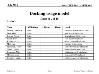
802.11: Passive/Active Scanning
passive scanning:
(1)
beacon frames sent from APs
- periodically, every 100 ms
(2)
Association Request frame
sent: H1 to selected AP
(3)
Association Response frame
sent from selected AP to H1
active scanning
:
(1)
Probe Request frame broadcast
from H1
(2)
Probe Response frames sent
from APs
(3)
Association Request frame
sent: H1 to selected AP
(4)
Association Response frame
sent from selected AP to H1
18
IEEE 802.11: Multiple Access
Avoid collisions: 2
+
nodes
transmitting at same time
CSMA - sense before transmitting
»
don
’
t collide with ongoing transmission by another node
No
collision detection!
»
difficult to receive (sense collisions) when transmitting due to
weak received signals (fading)
»
can
’
t sense all collisions in any case: hidden terminal, fading
»
goal:
avoid collisions
:
CSMA/CA (collision avoidance)
19
IEEE 802.11 MAC Protocol: CSMA/CA
802.11 sender
if sense channel idle for
DIFS
then
»
transmit entire frame (no CD)
if sense channel busy then
»
start random
backoff timer
•
timer counts down while channel
idle
–
when channel is busy, timer stops
–
may start/stop multiple times
•
transmit when timer expires
»
if no ACK, increase random backoff
interval, and try again
802.11 receiver
»
if frame received OK
»
return ACK after
SIFS
(ACK needed due
to hidden terminal problem)
Timing – 11 Mb/s is 11 bits/
s, propagation time <1
s
20
Basic Transmission Procedure
•
Variable
InterFrame Space
(
IFS
) between transmissions
•
DCF IFS (DIFS) to transmit data, RTS (next slide), etc.
•
Followed by contention period
•
When channel becomes idle
•
“Priority” frames wait only for Short IFS (SIFS)
•
Completion of in-progress transfer, ACKs, CTS, etc.
•
PCF IFS (PIFS) to initiate Contention-Free Periods
21
Avoiding Collisions
A
llow sender to
“
reserve
”
channel rather than random
access of data frames
»
avoid collisions of long data frames
»
optional feature
Sender first transmits
small
request-to-send (RTS)
packets to Access Point using CSMA
»
RTSs may still collide with each other (but they
’
re short)
•
less than 50 bytes, vs 1500 bytes for largest Ethernet frame
AP broadcasts clear-to-send CTS in response to RTS
CTS heard by all nodes
»
RTS and CTS contain duration of frame time
»
sender transmits data frame
»
other stations defer transmissions for that duration
even if
they don’t hear anything during that time
22
Collision Avoidance: RTS-CTS Exchange
23
Properties of RTS/CTS Operation
Nodes that see CTS refrain from transmitting for specified
duration
»
Addresses hidden terminal problem (I did not hear you, but I
heard the receiver with which I would have interfered)
Nodes that see RTS but not CTS can proceed to transmit
»
Addresses exposed node problem (I heard you but not the
receiver, and so I know I wont interfere with your transmission to
that receiver) – only relevant in ad hoc mode
Collisions of RTS messages detected through lack of CTS
response
»
Exponential backoff algorithm for retransmissions
RTS/CTS procedure used only for frames above a certain
length
»
Small frames are sent “immediately” (configurable parameter) to
avoid RTS/CTS overhead
24
25
Data
SIFS
Busy medium
ACK
DIFS
NAV (RTS)
Source
Destination
Others
RTS
DIFS
SIFS
CTS
SIFS
NAV (CTS)
NAV (Data)
NAV
: Network allocation vector, specifies amount of time the sender expects to keep
the medium busy (max of 32.767 ms)
802.11 Frame Format
Additional address fields compared to standard E/N frame
»
ToDS and FromDS determines the content of those fields
Type/Subtype indicates type of frame: management (00), control (01), or data (10)
More fragment indicates that large frame was fragmented
Retry indicates retransmission of previous fragment
WEP means body is encrypted according to WEP alg.
Duration/ID typically specifies amount of time channel will remain busy (NAV = Xmit +
ACK) NAV = Network Allocation Vector
Sequence control specifies fragment and sequence numbers to recognize duplicates
26
More Details
27
Address details on next slide
802.11 Frame: Addressing
28
Address Example on next slide
802.11 Addressing
29
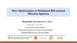
802.11 Rate Adaptation
(experimental)
Dynamically change
modulation technique in
response to changes in SNR
»
SNR decreases, BER increases as
node moves away from base station
»
when BER becomes too high, switch
to lower transmission rate but with
lower BER
Simple adaptation method
»
if
two
consecutive frame
transmissions fail (no ack after
several retries)”down-shift”
»
if
ten
consecutive frame
transmissions succeed, “up-shift”
30
802.11 Power Management
Node-to-AP: “I am going to sleep until next beacon
frame”
»
AP knows not to transmit frames to this node
»
node wakes up before next beacon frame
Beacon frame: contains list of mobiles with AP-to-mobile
frames waiting to be sent
»
node will stay awake if AP-to-mobile frames to be sent;
otherwise sleep again until next beacon frame
31
802.15: Personal Area Network
Less than 10 m diameter
Replacement for cables
»
mouse, keyboard, headphones
Ad hoc: no infrastructure
Master/slaves:
»
slaves request permission to
send (to master)
»
master grants requests
802.15: evolved from
Bluetooth specification
»
2.4-2.5 GHz, up to 4 Mb/s
»
TDM with 79 channels
•
uses “channel hopping”
»
up to 721 kbps
32
Exercise: Two CDMA senders
1.
How would a receiver successfully receive the data
sent by sender 1 (or 2)?
Sender 1
Sender 2
channel sums transmissions
by senders 1 and 2
33
using same code as sender 1,
receiver recovers sender 1
’
s
original data from summed
channel data!
Sender 1
Sender 2
channel sums transmissions
by senders 1 and 2
34
1x0+1x(-2)+1x0+(-1)x2+1x0+(-1)x0+(-1)x2+(-1)x2=-8
-1
1x2+1x0+1x2+(-1)x0+1x2+(-1)x(-2)+(-1)x0+(-1)x0=+8
1
Exercise: Two CDMA senders
Exercises
2.
Suppose nodes
A,
B
and
C
are in an 802.11 network with access point
X
and
assume that
A
and
B
can hear each other,
A
and
C
can hear each other, but
B
and
C
cannot hear each other. Assume RTS/CTS is not turned on. Suppose that
at time 0,
X
is sending a packet and it continues to send for 500
s
. At time
100,
A
gets a packet to send and initializes its backoff timer to 400
s
. At time
200,
B
gets a packet to send and initializes its backoff timer to 300
s
. At time
400,
C
gets a packet to send and initializes its backoff timer to 100
s
. Assume
that it takes 200
s
to send each of the packets from
A
,
B
and
C
. When do each
of the hosts start sending their packets. Which of them is delivered successfully,
and when? You can ignore time spent on ACKs and/or *IFS.
35
Exercise
2.
Suppose nodes
A,
B
and
C
are in an 802.11 network with access point
X
and
assume that
A
and
B
can hear each other,
A
and
C
can hear each other, but
B
and
C
cannot hear each other. Assume RTS/CTS is not turned on. Suppose that
at time 0,
X
is sending a packet and it continues to send for 500
s
. At time
100,
A
gets a packet to send and initializes its backoff timer to 400
s
. At time
200,
B
gets a packet to send and initializes its backoff timer to 300
s
. At time
400,
C
gets a packet to send and initializes its backoff timer to 100
s
. Assume
that it takes 200
s
to send each of the packets from
A
,
B
and
C
. When do each
of the hosts start sending their packets. Which of them is delivered successfully,
and when? You can ignore time spent on ACKs and/or *IFS.
Since X is transmitting until t=500, none of the hosts decrement their backoff
timer until that point, so they all start with their original values even though
they initialized them at different times. This means that C gets to transmit first
at t=600, which is when its backoff timer of 100 expires. At that time, the
backoff timer values of A and B are 300 and 200, respectively. Because A can
hear C, its timer will be frozen for the next 200
s while C transmits, but B
continues decrementing its timer. At t=800 C completes its transmission just in
time to avoid interfering with B’s transmission that starts then. Because A can
hear the transmission from B, its keeps its backoff timer frozen until t= 1000,
which is when B completes its transmission. A will then wait another 300
s
until its backoff timer decrements to 0, before it starts its own transmission. In
this scenario all three transmissions are successful.
36
Exercises
3.
Repeat the last problem assuming RTS/CTS is turned on. Assume that it takes
just 20
s
to send an RTS or a CTS.
37
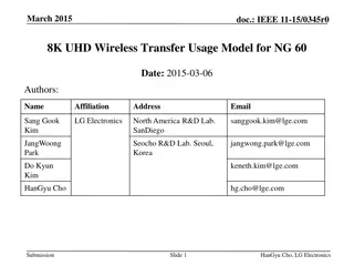
Exercises
3.
Repeat the last problem assuming RTS/CTS is turned on. Assume that it takes
20
s
to send an RTS or a CTS.
Because all three nodes (A,B,C) sense a busy channel when they first have to
send a frame, they select a random backoff time (400
s, 300
s, and 100
s for
A, B, and C, respectively) that determines when they will send their RTS.
C’s timer is the first to expire and it sends its RTS at t=600. The impact of the
RTS depends on who can hear it (everyone hears the CTS since it comes from
the AP), i.e., who realizes that the medium has become busy due to the RTS
transmission. In our scenario, A hears C’s RTS but B does not. Hence, A will
freeze its timer, but B continues decrementing its own until it starts receiving
the CTS (destined to C) sent by X 20
s later. At this point (t=620), A’s timer is
300, and B’s is 180. Both A’s and B’s timers stay frozen while the CTS is
received and then for the duration of the value carried in C’s CTS, i.e., 200
s,
which is how long it will take C to transmit its packet and have it acknowledged.
Hence, A’s and B’s timers remain frozen until t=840, at which point they both
start decrementing again.
This results in B sending its RTS at t=840+180=1020 and receiving its CTS at
t=1060. Note that because A can hear B, it freezes its timer at t=1020 at a
value of 300-180=120. B’s CTS again carries a duration value of 200
s, which
will keep A’s timer frozen until t=1260.
A eventually transmits its own RTS at t=1260+120=1380, and receives a CTS
from X at t=1420, at which points it starts transmitting (and ends at t=1620).
38
Transmission Timeline under RTS/CTS
39
Exercises
4.
Consider a packet going from a host
A
on a wireless network with access point
X
through an Ethernet switch to a router
R
. From there, it goes back to the switch
to another access point
Y
, which delivers it to a host
B
. What MAC addresses
appear in the three address fields of the 802.11 frame sent over
A
’s wireless
network. What MAC addresses appear in the two address fields of the Ethernet
frame sent to the router? What MAC addresses appear in the three address
fields of the 802.11 packet sent over
B
’s wireless network?
40
Exercises
4.
Consider a packet going from a host
A
on a wireless network with access point
X
through an Ethernet switch to a router
R
. From there, it goes back to the switch
to another access point
Y
, which delivers it to a host
B
. What MAC addresses
appear in the three address fields of the 802.11 frame sent over
A
’s wireless
network. What MAC addresses appear in the two address fields of the Ethernet
frame sent to the router? What MAC addresses appear in the three address
fields of the 802.11 packet sent over
B
’s wireless network?
The MAC addresses in the 802.11 frame sent by A are as follows: X,A,R
The MAC addresses in the Ethernet frame forwarded by X are: R,A
The MAC addresses in the Ethernet frame forwarded by R are: B,R (B is obtained
from the ARP query issued by R using the IP address of B’s host)
The MAC addresses in the 802.11 frame sent by Y are: B,Y,R
41
Exercises
5.
Consider a host
A
in an 802.11 network that is using power management.
Suppose that some remote host is sending an average of 20 packets per second
to
A
and the packets have an average length of 1000 bytes. Approximately what
fraction of the time can
A
sleep? Assume no other activity in the network.
42
Exercises
5.
Consider a host
A
in an 802.11b network that is using power management.
Suppose that some remote host is sending an average of 20 packets per second
to
A
and the packets have an average length of 1000 bytes. Approximately what
fraction of the time can
A
sleep? Assume no other activity in the network.
Host A receives on average 160,000 bits/sec. Assuming a 11 Mbps transmission
speed, this translates into a transmission time of 14.55 ms.
After receiving the 20 packets, the host will notify that it will be going to sleep
until the next beacon frame(sent every 100ms), and wake up at that time only
to go back to sleep and repeat the process 9 more times until it receives a
beacon indicating there are frames pending for A to receive.
Hence, ignoring the wake-up times spent receiving beacon frames, node A
spends approximately 98.5% of its time asleep.
If we don’t ignore the wake-up times, we would need to add to the reception
times of 14.55 ms, the total time consumed by the wake-up process, namely,
10*250
s or 2.5 ms. This results in a total “non-sleeping” time of 17.05 ms, or
alternatively a 98.3% fraction of time sleeping.
43
Exercises
6.
Consider an 802.11b network that uses the simple rate adjustment scheme
described on the slide titled “802.11 Rate Adaptation (experimental)” (highlights
shown below) with three modulation schemes. Assuming that frames are
10,000 bits and that the SNR is 9 dB, what are the odds we can switch from the
low rate modulation scheme to the middle? Is this a good idea? What other
(better) rate adaptation scheme could you suggest?
44
Simple adaptation method
»
if
two
consecutive frame
transmissions fail (no ack after
several retries)”down-shift”
»
if
ten
consecutive frame
transmissions succeed, “up-shift”
Exercises
6.
Consider an 802.11b network that uses the simple rate adjustment scheme
described on the slide titled “802.11 Rate Adaptation (experimental)” with three
modulation schemes. Assuming that frames are 10,000 bits and that the SNR is
9 dB, what are the odds we can switch from the low rate modulation scheme to
the middle? Is this a good idea? What other (better) rate adaptation scheme
could you suggest?
With an SNR of 9 dB, the BER is about 10
-7
when using the low rate modulation
scheme. Assuming 10,000 bit frames, receiving 10 error-free frames means
receiving 100,000 bits without errors. This has a probability of
(1- 10
-7
)
100,000
~ (1-100,000x10
-7
)=0.99. So the odds that we will switch are
pretty high.
Now, with an SNR of 9 db, the BER at the middle modulation rate is now about
0.1. This means that we are most likely to experience two consecutive failed
frame transmissions (the odds of at least one bit in error in a 10,000 bits frame
are close to 1), and hence switch right back to the lower rate modulation. The
back and forth between rates that will ensue is not a good idea.
A better rate adaptation option would rely on directly measuring the SNR and
switching only when it is safe to do so, i.e., the BER at the higher rate
modulation still yields an acceptable BER.
45
Wireless networks play a vital role in our modern world, with mobile devices outnumbering wired connections. This overview covers wireless network fundamentals, including elements, characteristics of wireless links, ad hoc operations, and network classifications like mesh networks and MANET.

Download Presentation

Please find below an Image/Link to download the presentation.
The content on the website is provided AS IS for your information and personal use only. It may not be sold, licensed, or shared on other websites without obtaining consent from the author.If you encounter any issues during the download, it is possible that the publisher has removed the file from their server.
You are allowed to download the files provided on this website for personal or commercial use, subject to the condition that they are used lawfully. All files are the property of their respective owners.
The content on the website is provided AS IS for your information and personal use only. It may not be sold, licensed, or shared on other websites without obtaining consent from the author.
E N D
Presentation Transcript
21. Wireless Internet General wireless network issues WiFi channels and association CSMA/CA packet header fields Roch Guerin (with adaptations from Jon Turner and John DeHart, and material from Kurose and Ross)
Wireless and Mobile Networks Background: # wireless (mobile) phone subscribers now far exceed # wired phone subscribers # wireless Internet-connected devices surpasses # wired Internet-connected devices laptops, Internet-enabled phones promise anytime untethered Internet access Internet-of-Things will give this yet another boost two important (but different) challenges wireless: communication over wireless link mobility: handling the mobile user who changes point of attachment to network CSE574: Wireless and Mobile Networking 2
Elements of a Wireless Network wireless hosts -laptop, phone -run apps -may be mobile or stationary base stations -typically connected to wired network -relay - responsible for sending packets between wired network and wireless host(s) in its area -e.g., cell towers, 802.11 access points network infrastructure wireless links -typically used to connect mobile(s) to base station -also used as backbone link -multiple access protocol coordinates link access -various data rates, transmission distance 3
Characteristics of Wireless Links 5G (2020) 200 802.11n 54 802.11a,g 802.11a,g point-to-point Data rate (Mbps) 5-11 802.11b 4G: LTWE WIMAX 4 3G: UMTS/WCDMA-HSPDA, CDMA2000-1xEVDO 1 802.15 .384 2.5G: UMTS/WCDMA, CDMA2000 .056 2G: IS-95, CDMA, GSM Indoor 10-30m Outdoor 50-200m Mid-range outdoor 200m 4 Km Long-range outdoor 5Km 20 Km 4
Ad hoc Operation No base stations or infrastructure nodes Nodes can only transmit to others within range Nodes organize and among themselves Notice each other Find they have something to share Cooperate to form network and forward packets 5
Wireless Network Classification multiple hops single hop host may have to relay through several wireless nodes to connect to larger Internet: mesh net host connects to base station (WiFi, WiMAX, cellular) which connects to larger Internet infrastructure (e.g., APs) no base station, no connection to larger Internet. May have to relay to reach other wireless nodes MANET, VANET no no base station, no connection to larger Internet (Bluetooth, ad hoc nets) infrastructure 6
IEEE 802.11 LAN Standards IEEE Standard 802.11 Rate Band Notes 1-2 Mbps Range ? 2.4 GHz 1997 Standard; FH & DSSS 1999 Standard; OFDM 802.11a Up to 54 Mbps (usually 25Mbps) Range ~ 30m 5-6 GHz (U.S.) 802.11b (Wi-Fi) Up to 11 Mbps (usually 6.5Mbps) Range ~ 30m 2.4 GHz 1999 Standard; DSSS CCK/QPSK 2003 Standard OFDM 802.11g Up to 54 Mbps (usually 25Mbps) Range ~ 30m 2.4 GHz 802.11n Up to 540 Mbps (usually 200Mbps) Range ~ 50m 2.4GHz or 5-6GHz 2009 Standard; MIMO + frame aggregation 7
IEEE 802.11 LAN Standards IEEE Standard 802.11 Rate Band Notes 1-2 Mbps Range ? 2.4 GHz 1997 Standard; FH & DSSS 1999 Standard; OFDM My office: netsh wlan show interfaces 802.11a Shows that my laptop connects over 802.11n with a speed that seems to vary between 270Mbps and 300Mbps Up to 54 Mbps (usually 25Mbps) Range ~ 30m 5-6 GHz (U.S.) 802.11b (Wi-Fi) Up to 11 Mbps (usually 6.5Mbps) Range ~ 30m 2.4 GHz 1999 Standard; DSSS CCK/QPSK 2003 Standard OFDM 802.11g Up to 54 Mbps (usually 25Mbps) Range ~ 30m 2.4 GHz 802.11n Up to 540 Mbps (usually 200Mbps) Range ~ 50m 2.4GHz or 5-6GHz 2009 Standard; MIMO + frame aggregation 8
Basics of Spreading Gain Sender transmits S = 1 B +1 -1 -1 Receiver gets (S+J) and computes (S+J) B=S B+J B B B = +11 -B B = -11 J B = +1 Computation yields S = 1 B (S+J) B = +12 1 S = 0 -B (S+J) B = -10 0 +1 +1 +1 +1 +1 -1 -1 -1 S = 0 -B +1 +1 +1 +1 +1 -1 -1 -1 -1 -1 -1 Interference, say, continuously transmits J +1+1 +1 +1+1 +1 +1 +1 +1 +1 +1 9
Wireless Link Characteristics Differences from wired links decreased signal strength: radio signal attenuates as it propagates (path loss) much faster than when guided through wire interference from other sources: standardized wireless network frequencies (e.g., 2.4 GHz) shared by other devices (e.g., wireless phones, electric motors, microwave ovens) multipath propagation: radio signal reflects off objects and ground, arriving at destination at slightly different times Makes communication across (even point-to-point) wireless link more challenging Lower and variable achievable bit rates higher error rates limited distances without sophisticated antennas(beam-forming) On the flip side, this ensures limited propagation delays more vulnerable to snooping (signal is inherently broadcast) Stronger need for encryption 10
Wireless Link Characteristics SNR: signal-to-noise ratio larger SNR is good easier to separate signal from noise measured in decibels (db) logarithmic scale increase of 3 db corresponds to doubling ratio SNR versus BER tradeoffs signal power increased power leads to higher SNR and lower BER alternate modulation schemes more sophisticated methods yield higher data rate, but also higher BER can sometimes select modulation technique based on conditions 10-1 10-2 10-3 BER 10-4 10-5 10-6 10-7 10 20 30 40 SNR(dB) QAM256 (8 Mbps) QAM16 (4 Mbps) BPSK (1 Mbps) 11
Wireless Network Characteristics Multiple wireless senders and receivers create additional problems (beyond multiple access): A B C C C s signal strength A s signal strength B A distance Hidden terminal problem A, B hear each other, B, C hear each other A, C cannot hear each other, so may send simultaneously causing interference at B. A, C cannot detect collision can be caused by obstacle or signal attenuation over distance 12
Hidden Terminal Problem Hearing No One Does Not Mean I Can Transmit C B senses clear medium; A hidden from B (a) Data Frame B A A transmits frame C (b) Data Frame Data Frame Frames from A & B collide at C A B 13
Exposed Node Problem Hearing Someone Does Not Mean I Cannot Transmit D C B hears C and thinks that C s transmissions preclude talking to D A B D C A B But B can talk to D without interfering with C s transmissions to A 14
802.11 LAN Architecture Wireless host communicates with access point (AP) Wireless subnet called Basic Service Set (BSS) in infrastructure mode contains wireless hosts and access point (AP) in ad hoc mode, just hosts Internet hub, switch or router BSS 1 BSS 2 15
802.11: Channels 802.11b: 2.4GHz-2.5 GHz spectrum (unlicensed) divided into 11 channels with overlapping frequencies AP administrator chooses frequency for AP interference possible: channel can be same as that chosen by neighboring AP (or may overlap) 5MHz 30db 1 2 3 4 5 6 7 8 9 10 11 16
802.11: Association Host: must associate with an AP scans channels, listening for beacon frames containing AP s name (SSID) and MAC address selects AP to associate with may perform authentication will typically run DHCP to get IP address in AP s subnet 17
802.11: Passive/Active Scanning BSS 1 BSS 1 BSS 2 BSS 2 1 AP 2 1 1 2 3 2 AP 2 AP 1 AP 1 2 4 3 H1 H1 active scanning: (1) Probe Request frame broadcast from H1 (2) Probe Response frames sent from APs (3) Association Request frame sent: H1 to selected AP (4) Association Response frame sent from selected AP to H1 passive scanning: (1) beacon frames sent from APs - periodically, every 100 ms (2) Association Request frame sent: H1 to selected AP (3) Association Response frame sent from selected AP to H1 18
IEEE 802.11: Multiple Access Avoid collisions: 2+ nodes transmitting at same time CSMA - sense before transmitting don t collide with ongoing transmission by another node No collision detection! difficult to receive (sense collisions) when transmitting due to weak received signals (fading) can t sense all collisions in any case: hidden terminal, fading goal: avoid collisions: CSMA/CA (collision avoidance) B A C C C s signal strength A s signal strength B A space 19
IEEE 802.11 MAC Protocol: CSMA/CA 802.11 sender if sense channel idle for DIFS then transmit entire frame (no CD) if sense channel busy then start random backoff timer timer counts down while channel idle when channel is busy, timer stops may start/stop multiple times transmit when timer expires if no ACK, increase random backoff interval, and try again 802.11 receiver if frame received OK return ACK after SIFS(ACK needed due to hidden terminal problem) Timing 11 Mb/s is 11 bits/ s, propagation time <1 s sender receiver DIFS data SIFS ACK 20
Basic Transmission Procedure Contention window DIFS PIFS DIFS Data frame SIFS Busy medium Time Pick transmission time randomly Defer access Variable InterFrame Space (IFS) between transmissions DCF IFS (DIFS) to transmit data, RTS (next slide), etc. Followed by contention period When channel becomes idle Priority frames wait only for Short IFS (SIFS) Completion of in-progress transfer, ACKs, CTS, etc. PCF IFS (PIFS) to initiate Contention-Free Periods 21
Avoiding Collisions Allow sender to reserve channel rather than random access of data frames avoid collisions of long data frames optional feature Sender first transmits small request-to-send (RTS) packets to Access Point using CSMA RTSs may still collide with each other (but they re short) less than 50 bytes, vs 1500 bytes for largest Ethernet frame AP broadcasts clear-to-send CTS in response to RTS CTS heard by all nodes RTS and CTS contain duration of frame time sender transmits data frame other stations defer transmissions for that duration even if they don t hear anything during that time 22
Collision Avoidance: RTS-CTS Exchange B A AP reservation collision DATA (A) defer time 23
Properties of RTS/CTS Operation Nodes that see CTS refrain from transmitting for specified duration Addresses hidden terminal problem (I did not hear you, but I heard the receiver with which I would have interfered) Nodes that see RTS but not CTS can proceed to transmit Addresses exposed node problem (I heard you but not the receiver, and so I know I wont interfere with your transmission to that receiver) only relevant in ad hoc mode Collisions of RTS messages detected through lack of CTS response Exponential backoff algorithm for retransmissions RTS/CTS procedure used only for frames above a certain length Small frames are sent immediately (configurable parameter) to avoid RTS/CTS overhead 24
DIFS RTS Data Source SIFS SIFS SIFS ACK CTS Destination DIFS NAV (RTS) NAV (CTS) Others NAV (Data) Busy medium NAV: Network allocation vector, specifies amount of time the sender expects to keep the medium busy (max of 32.767 ms) 25
802.11 Frame Format 2 2 6 0-2312 4 6 6 2 6 Frame Control Duration/ ID Address 1 Address 2 Address 3 Sequence control Address 4 Frame body CRC e.g. StaAP1 AP1 StaAPn frame from DS Incl. 8 bytes WEP, 8 bytes LLC MAC Header (bytes) Protocol Version To DS From DS More FragRetryPwr More DataWEPRsvd Type Subtype Mgt Additional address fields compared to standard E/N frame ToDS and FromDS determines the content of those fields Type/Subtype indicates type of frame: management (00), control (01), or data (10) More fragment indicates that large frame was fragmented Retry indicates retransmission of previous fragment WEP means body is encrypted according to WEP alg. Duration/ID typically specifies amount of time channel will remain busy (NAV = Xmit + ACK) NAV = Network Allocation Vector Sequence control specifies fragment and sequence numbers to recognize duplicates 26
More Details frame seq # (for RDT) duration of reserved transmission time (RTS/CTS) 6 4 2 bytes 2 6 6 6 2 0 - 2312 frame controldurationaddress address 2 address 3 address 4 seq control payload CRC 1 2 bits 2 4 1 1 1 1 1 1 1 1 Protocol version To AP From AP More frag Power mgt More data Type Subtype Retry WEP Rsvd Address details on next slide frame type (RTS, CTS, ACK, data) 27
802.11 Frame: Addressing 6 4 2B 2 6 6 6 2 0 - 2312 frame controldurationaddress address 2 address 3 address 4 seq control payload CRC 1 Address 4: used only in ad hoc mode (to support per-hop addresses) Address 1: MAC address of wireless host or AP to receive this frame Address 3: MAC address of router in switched subnet to which AP is attached Address 2: MAC address of wireless host or AP transmitting this frame Address Example on next slide 28
802.11 Addressing Internet router H1 R1 R1 MAC addr H1 MAC addr source address dest. address Ethernet frame AP MAC addr H1 MAC addr R1 MAC addr address 3 address 2 802.11 frame address 1 29
802.11 Rate Adaptation (experimental) Dynamically change modulation technique in response to changes in SNR SNR decreases, BER increases as node moves away from base station when BER becomes too high, switch to lower transmission rate but with lower BER Simple adaptation method if two consecutive frame transmissions fail (no ack after several retries) down-shift if ten consecutive frame transmissions succeed, up-shift 10-1 10-2 10-3 BER 10-4 10-5 10-6 10-7 10 20 30 40 SNR(dB) 11 Mbps 6 Mbps 1 Mbps 30
802.11 Power Management Node-to-AP: I am going to sleep until next beacon frame AP knows not to transmit frames to this node node wakes up before next beacon frame Beacon frame: contains list of mobiles with AP-to-mobile frames waiting to be sent node will stay awake if AP-to-mobile frames to be sent; otherwise sleep again until next beacon frame 31
802.15: Personal Area Network Less than 10 m diameter Replacement for cables mouse, keyboard, headphones Ad hoc: no infrastructure Master/slaves: slaves request permission to send (to master) master grants requests 802.15: evolved from Bluetooth specification 2.4-2.5 GHz, up to 4 Mb/s TDM with 79 channels uses channel hopping up to 721 kbps P S P radius of coverage M P S S P Master device M Slave device S Parked device (inactive) P 32
Exercise: Two CDMA senders channel sums transmissions by senders 1 and 2 Sender 1 Sender 2 1. How would a receiver successfully receive the data sent by sender 1 (or 2)? 33
Exercise: Two CDMA senders channel sums transmissions by senders 1 and 2 Sender 1 Sender 2 using same code as sender 1, receiver recovers sender 1 s original data from summed channel data! 1x0+1x(-2)+1x0+(-1)x2+1x0+(-1)x0+(-1)x2+(-1)x2=-8 -1 1x2+1x0+1x2+(-1)x0+1x2+(-1)x(-2)+(-1)x0+(-1)x0=+8 1 34
X Exercises C B A 2. Suppose nodes A,B and C are in an 802.11 network with access point X and assume that A and B can hear each other, A and C can hear each other, but B and C cannot hear each other. Assume RTS/CTS is not turned on. Suppose that at time 0, X is sending a packet and it continues to send for 500 s. At time 100, A gets a packet to send and initializes its backoff timer to 400 s. At time 200, B gets a packet to send and initializes its backoff timer to 300 s. At time 400, C gets a packet to send and initializes its backoff timer to 100 s. Assume that it takes 200 s to send each of the packets from A, B and C. When do each of the hosts start sending their packets. Which of them is delivered successfully, and when? You can ignore time spent on ACKs and/or *IFS. 35
X Exercise C B A 2. Suppose nodes A,B and C are in an 802.11 network with access point X and assume that A and B can hear each other, A and C can hear each other, but B and C cannot hear each other. Assume RTS/CTS is not turned on. Suppose that at time 0, X is sending a packet and it continues to send for 500 s. At time 100, A gets a packet to send and initializes its backoff timer to 400 s. At time 200, B gets a packet to send and initializes its backoff timer to 300 s. At time 400, C gets a packet to send and initializes its backoff timer to 100 s. Assume that it takes 200 s to send each of the packets from A, B and C. When do each of the hosts start sending their packets. Which of them is delivered successfully, and when? You can ignore time spent on ACKs and/or *IFS. Since X is transmitting until t=500, none of the hosts decrement their backoff timer until that point, so they all start with their original values even though they initialized them at different times. This means that C gets to transmit first at t=600, which is when its backoff timer of 100 expires. At that time, the backoff timer values of A and B are 300 and 200, respectively. Because A can hear C, its timer will be frozen for the next 200 s while C transmits, but B continues decrementing its timer. At t=800 C completes its transmission just in time to avoid interfering with B s transmission that starts then. Because A can hear the transmission from B, its keeps its backoff timer frozen until t= 1000, which is when B completes its transmission. A will then wait another 300 s until its backoff timer decrements to 0, before it starts its own transmission. In this scenario all three transmissions are successful. 36
X Exercises C B A 3. Repeat the last problem assuming RTS/CTS is turned on. Assume that it takes just 20 s to send an RTS or a CTS. 37
X Exercises C B A 3. Repeat the last problem assuming RTS/CTS is turned on. Assume that it takes 20 s to send an RTS or a CTS. Because all three nodes (A,B,C) sense a busy channel when they first have to send a frame, they select a random backoff time (400 s, 300 s, and 100 s for A, B, and C, respectively) that determines when they will send their RTS. C s timer is the first to expire and it sends its RTS at t=600. The impact of the RTS depends on who can hear it (everyone hears the CTS since it comes from the AP), i.e., who realizes that the medium has become busy due to the RTS transmission. In our scenario, A hears C s RTS but B does not. Hence, A will freeze its timer, but B continues decrementing its own until it starts receiving the CTS (destined to C) sent by X 20 s later. At this point (t=620), A s timer is 300, and B s is 180. Both A s and B s timers stay frozen while the CTS is received and then for the duration of the value carried in C s CTS, i.e., 200 s, which is how long it will take C to transmit its packet and have it acknowledged. Hence, A s and B s timers remain frozen until t=840, at which point they both start decrementing again. This results in B sending its RTS at t=840+180=1020 and receiving its CTS at t=1060. Note that because A can hear B, it freezes its timer at t=1020 at a value of 300-180=120. B s CTS again carries a duration value of 200 s, which will keep A s timer frozen until t=1260. A eventually transmits its own RTS at t=1260+120=1380, and receives a CTS from X at t=1420, at which points it starts transmitting (and ends at t=1620). 38
Transmission Timeline under RTS/CTS X C B A CTS CTS CTS Transmit X 1400 1420 620 640 1040 1060 500 0 300 0 RTS 120 300 120 400 Transmit 1420 timer timer timer 100 A 1380 840 1260 1620 1020 600 500 0 180 180 RTS 0 300 Transmit 1060 timer timer B 200 840 620 1260 500 1020 0 0 100 RTS Transmit 640 timer 300 C 600 840 0 500 39
Exercises 4. Consider a packet going from a host A on a wireless network with access point X through an Ethernet switch to a router R. From there, it goes back to the switch to another access point Y, which delivers it to a host B. What MAC addresses appear in the three address fields of the 802.11 frame sent over A s wireless network. What MAC addresses appear in the two address fields of the Ethernet frame sent to the router? What MAC addresses appear in the three address fields of the 802.11 packet sent over B s wireless network? 40
Exercises 4. Consider a packet going from a host A on a wireless network with access point X through an Ethernet switch to a router R. From there, it goes back to the switch to another access point Y, which delivers it to a host B. What MAC addresses appear in the three address fields of the 802.11 frame sent over A s wireless network. What MAC addresses appear in the two address fields of the Ethernet frame sent to the router? What MAC addresses appear in the three address fields of the 802.11 packet sent over B s wireless network? The MAC addresses in the 802.11 frame sent by A are as follows: X,A,R The MAC addresses in the Ethernet frame forwarded by X are: R,A The MAC addresses in the Ethernet frame forwarded by R are: B,R (B is obtained from the ARP query issued by R using the IP address of B s host) The MAC addresses in the 802.11 frame sent by Y are: B,Y,R 41
Exercises 5. Consider a host A in an 802.11 network that is using power management. Suppose that some remote host is sending an average of 20 packets per second to A and the packets have an average length of 1000 bytes. Approximately what fraction of the time can A sleep? Assume no other activity in the network. 42
Exercises 5. Consider a host A in an 802.11b network that is using power management. Suppose that some remote host is sending an average of 20 packets per second to A and the packets have an average length of 1000 bytes. Approximately what fraction of the time can A sleep? Assume no other activity in the network. Host A receives on average 160,000 bits/sec. Assuming a 11 Mbps transmission speed, this translates into a transmission time of 14.55 ms. After receiving the 20 packets, the host will notify that it will be going to sleep until the next beacon frame(sent every 100ms), and wake up at that time only to go back to sleep and repeat the process 9 more times until it receives a beacon indicating there are frames pending for A to receive. Hence, ignoring the wake-up times spent receiving beacon frames, node A spends approximately 98.5% of its time asleep. If we don t ignore the wake-up times, we would need to add to the reception times of 14.55 ms, the total time consumed by the wake-up process, namely, 10*250 s or 2.5 ms. This results in a total non-sleeping time of 17.05 ms, or alternatively a 98.3% fraction of time sleeping. 43
Exercises 6. Consider an 802.11b network that uses the simple rate adjustment scheme described on the slide titled 802.11 Rate Adaptation (experimental) (highlights shown below) with three modulation schemes. Assuming that frames are 10,000 bits and that the SNR is 9 dB, what are the odds we can switch from the low rate modulation scheme to the middle? Is this a good idea? What other (better) rate adaptation scheme could you suggest? 10-1 10-2 10-3 BER 10-4 Simple adaptation method if two consecutive frame transmissions fail (no ack after several retries) down-shift if ten consecutive frame transmissions succeed, up-shift 10-5 10-6 10-7 10 20 30 40 SNR(dB) 11 Mbps 6 Mbps 1 Mbps 44
Exercises 6. Consider an 802.11b network that uses the simple rate adjustment scheme described on the slide titled 802.11 Rate Adaptation (experimental) with three modulation schemes. Assuming that frames are 10,000 bits and that the SNR is 9 dB, what are the odds we can switch from the low rate modulation scheme to the middle? Is this a good idea? What other (better) rate adaptation scheme could you suggest? With an SNR of 9 dB, the BER is about 10-7 when using the low rate modulation scheme. Assuming 10,000 bit frames, receiving 10 error-free frames means receiving 100,000 bits without errors. This has a probability of (1- 10-7)100,000 ~ (1-100,000x10-7)=0.99. So the odds that we will switch are pretty high. Now, with an SNR of 9 db, the BER at the middle modulation rate is now about 0.1. This means that we are most likely to experience two consecutive failed frame transmissions (the odds of at least one bit in error in a 10,000 bits frame are close to 1), and hence switch right back to the lower rate modulation. The back and forth between rates that will ensue is not a good idea. A better rate adaptation option would rely on directly measuring the SNR and switching only when it is safe to do so, i.e., the BER at the higher rate modulation still yields an acceptable BER. 45


")