Overview of External Wireless Communication System on International Space Station (ISS)
This presentation covers the overview and experience of implementing an external 802.11n wireless communication system on the International Space Station (ISS). It discusses the existing wireless system, committed users, system architecture, and future challenges. The system provides high data rate wireless capability to payloads on the Express Logistic Carrier (ELC) using Commercial Off-The-Shelf (COTS) solutions. It details the segments, operational locations, and planned utilization of the wireless system on the ISS. Various payloads and users are characterized for wireless integration. Additionally, the presentation highlights the Joint Station LAN (JSL) architecture and the logical LAN overview for interoperability requirements. The current external wireless communications architecture encompasses multiple components and configurations for seamless connectivity in space.
Download Presentation

Please find below an Image/Link to download the presentation.
The content on the website is provided AS IS for your information and personal use only. It may not be sold, licensed, or shared on other websites without obtaining consent from the author.If you encounter any issues during the download, it is possible that the publisher has removed the file from their server.
You are allowed to download the files provided on this website for personal or commercial use, subject to the condition that they are used lawfully. All files are the property of their respective owners.
The content on the website is provided AS IS for your information and personal use only. It may not be sold, licensed, or shared on other websites without obtaining consent from the author.
E N D
Presentation Transcript
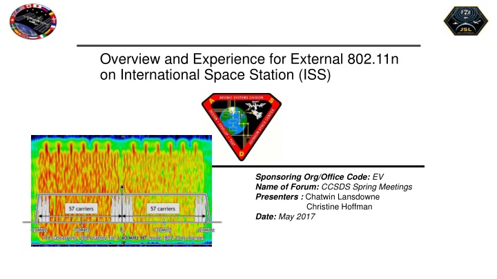
Overview and Experience for External 802.11n on International Space Station (ISS) Sponsoring Org/Office Code: EV Name of Forum: CCSDS Spring Meetings Presenters : Chatwin Lansdowne Christine Hoffman Date: May 2017
Topics ISS External Wireless Communication subsystem overview Existing Future Experience: what was easy, and challenges 2
The Current External Wireless System The Express Logistic Carrier (ELC) Wireless system provides a COTS solution for external high data rate 802.11n wireless capability to payloads on the ELC The system consists of two separate segments US Lab COTS Wireless Access Points (WAP) placed inside the lab with external antennas to provide the core wireless capability Payloads/Users Characterization of a wireless solution for the payloads/users to integrate and provide piece parts to the developers 3
EWC Committed Users EWC Client On-orbit Date Operating Location(s) NREP Operational JEM-EF; utilization will ramp up EHDC Operational Truss CP8, CP9; CP13, CP3 planned; coverage coupled to pan-tilt MUSES 5/2017 SpX-11 ELC-4; utilization will ramp up EcoSTRESS 4/2018 SpX-15 JEM-EF site 10; HISUI and NRAL disrupt coverage CR15502 EMU Data Recorder ~6/2018 Suited EVA ops CR15277 NanoRacks AirLock 12/2018 SpX-18 SSRMS port nadir, POA temp stow truss port nadir DDVS 6/2020 SSRMS nadir inspections Other 802.11n, coexisting with EWC: JAXA iSEEP payload RRM-3 payload 4
JSL Logical LAN Overview Ref: SSP 50892 Ethernet Requirements for Interoperability with the Joint Station LAN (JSL) 6
Current External Wireless Communications (EWC) Architecture All Links Wireless 802.11n 5GHz Band ELC Payload Y US Regulatory Domain ELC Payload Z Wireless Media Converter PL Processor PL Processor P/L NIC Payload SSID MAC (Payload Data) HTTP, TCP WAP Config MAC (Payload Data) HTTP, TCP WAP Config ELC Payload X MSL SSID PL Processor USB NIC MAC Packets Payload SSID Cameras USL JSL IP Address JSL IP Address UDP WAP 1 WAP 2 RF Connection Trunk Ports to ER PL VLAN MSL VLAN MSL IP Address Ethernet Connection Initial Config WAP 1 Connected to both antennas (2x2 MIMO) WAP 2 Cold Backup (original config) Pending installation of second WAP connected to the other antenna, so both will be operational ER 7
EWC Antenna Coverage Zones Zenith view Nadir view Some Assumptions and Caveats apply.. 8
Coverage Expansion Projects Approved Second internal WAP with additional antennas on US Lab Internal WAP with antennas on Node 3 Truss Cable runs supporting up to 10 connections for GbE Up to 6 EHDC camera clients dual-purposed or re-purposed as externally mounted WAPs Concept Ram shadow 9
Achievements Communication can inexpensively be provided to payloads and infrastructure by leveraging worldwide investment in miniaturized COTS, standards, and open-source block-buy investments and accumulation of knowledge about components consortium interoperability testing 10
Challenges: Challenges: Network and Protocol User Interaction A high-rate UDP streamer (e.g. video) can deny service to all users of an access point (inclusive of self), when channel is weak and connection speed drops below stream rate. This is a challenge for moveable or mobile video applications. Hidden Node will happen between port and starboard payloads Exposed Node could happen due to channel reuse 11
Chronology of 802.11n/ac 5GHz MAC and PHY Chipset Release USB NIC Product Release Linux driver Release Linux driver Release Radiation Test Characterization Test Payload Operations WAP Chipset Release Product Release Radiation Test Characterization Test Flight Operations Chipset Release Product Release WAP Radiation Test Characterization Test Flight Operations Chipset Release Product Release USB NIC Radiation Test Chipset Release Product Release Module 2007 2008 2009 2010 2011 2012 2013 2014 2015 2016 2017 n Draft 1 802.11ae-2012 Prioritization of Management Frames 802.11aa-2012 Video Transport Streams n Draft 1 802.11ae-2012 Prioritization of Management Frames 802.11aa-2012 Video Transport Streams n Draft 2 n Draft 2 n Draft 3 n Draft 3 n Draft 4 WiFi n testing begins n Draft 4 n Draft 5 n Draft 6 n Draft 7 802.11ax-2019 802.11ac-2013 n Draft 5 WiFi n testing begins WiFi Draft 2.0 n testing begins 802.11ax-2019 802.11ac-2013 n Draft 6 WiFi Draft 2.0 n testing begins n Draft 7 802.11ac Wave 2 802.11ac Wave 2 n Drafts 8-11 802.11r-2008 Fast Roaming n Drafts 8-11 802.11k-2008 Radio Resource Measurement 802.11r-2008 Fast Roaming 802.11n-2009 EWC radios are not WiFi Certified interoperable. 802.11n-2009 802.11-2012 802.11-2012 802.11v-2011 Wireless Network Management 802.11k-2008 Radio Resource Measurement 9 drafts and 3 incorporated standards were released between the time the EWC chipsets were designed, and the release of 802.11-2009. The standard has continued to evolve. 802.11v-2011 Wireless Network Management 802.11w-2009 Protected Management Frames 802.11w-2009 Protected Management Frames
Penetrations Performance of ISS certified NATC / NZGL coaxial bulkheads and connectors is unspecified above 2.5GHz Mating performance suffers, as well as crimp performance A suitable replacement would enable internal radios with external antennas using carrier frequencies above 2.5GHz Available and Future technologies? DC-22GHz DC-40GHz DC-65GHz EXAMPLE 802.11n 40MHz signal, distorted by multipath 13
Challenges: Challenges: COTS Life of components is generally not specifiable or well-characterized NIC and WAP vendors go out of business Payloads prefer ISS program provides antennas and NIC Challenges: Challenges: Network Tendency of payloads to view connection speed not as shared Some clients do not support all channels in the country of sale. Clients must support a common channel set for manageability. 14
Challenges: Challenges: Radiation Roughly 75% of products radiation tested were unsuitable 802.11ac adapters are significantly harder than processors. 802.11ac WAPs have had especially soft processors Self-corrected failures observed Manually recoverable failures observed (soft restart, or hard restart) Unrecoverable: a WAP reset configuration to factory default including the default IP address Other failures damaged hardware, even started a fire 15
Challenges: Challenges: WAPs and NICs Most 802.11n devices are not WiFi Certified Some 802.11n devices on the market today are really Draft-n Not uncommon for output power or receiver sensitivity of an antenna connection to be 10dB to 30dB degraded after storage on ground 802.11ac WAPS generally cannot be configured as clients 16
Challenges: Challenges: Antennas Rigid antenna mounts: difficult to meet kick loads requirements; flexible antenna mounts can be a safety hazard Temptation to use dual antennas to increase spherical coverage at expense of network shared capacity and reliability of connection Polarization diversity: infrastructure began as vertical and clients had to match. Will become mixed: diverse linear, RHCP Temptation to use high-gain antennas and less infrastructure. High- gain antennas become a constraint on infrastructure, and are defeated by maximum EIRP requirement Temptation to build antennas in, but then coverage drives box design 17
COTS, Standards, Open Architecture Different standards solve different problems Each standard in the infrastructure represents a pool of COTS, tools, software opened to developers Standard Power Distance Data Rate Protection RFID passive 3m up to ~3kbps unlicensed BLE harvester, battery 20m up to ~3kbps unlicensed LoRaWAN harvester, battery 1km up to ~3kbps unlicensed ISA-100a battery 30m up to ~200kbps unlicensed WiFi battery, wired 100m up to ~1Gbps unlicensed LTE battery, wired 100km up to ~100Mbps licensed WiGig wired 50m up to ~7Gbps unlicensed EWC is a best-effort interface. Any interface based on a standard using unlicensed frequencies, is not usable for critical applications. 18


![[PDF⚡READ❤ONLINE] The International Space Station: Building for the Future (Spri](/thumb/21686/pdf-read-online-the-international-space-station-building-for-the-future-spri.jpg)

