Understanding Different Types of Chemical Reactors
Learn about the design and operation of batch reactors, CSTRs, PFRs, and PBRs in chemical engineering. Explore key concepts like molar balance, reaction rates, and reactor design equations for each reactor type.

Download Presentation

Please find below an Image/Link to download the presentation.
The content on the website is provided AS IS for your information and personal use only. It may not be sold, licensed, or shared on other websites without obtaining consent from the author. Download presentation by click this link. If you encounter any issues during the download, it is possible that the publisher has removed the file from their server.
E N D
Presentation Transcript
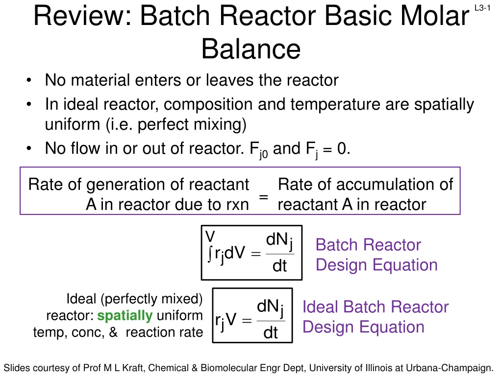
Review: Batch Reactor Basic Molar Balance No material enters or leaves the reactor In ideal reactor, composition and temperature are spatially uniform (i.e. perfect mixing) No flow in or out of reactor. Fj0 and Fj = 0. L3-1 Rate of generation of reactant A in reactor due to rxn Rate of accumulation of reactant A in reactor = V dN j Batch Reactor Design Equation = r dV j dt Ideal (perfectly mixed) reactor: spatially uniform temp, conc, & reaction rate dN Ideal Batch Reactor Design Equation j = r V j dt Slides courtesy of Prof M L Kraft, Chemical & Biomolecular Engr Dept, University of Illinois at Urbana-Champaign.
L3-2 Review: CSTR Basic Molar Balance Continuously add reactants and remove products In an ideal reactor, composition and temperature are spatially uniform (i.e. perfect mixing) At steady state- no accumulation Fj0 Fj Accumulation = In - Out + Generation by rxn 0 = Fj0 - Fj + V r jdV No spatial variation: rj V Ideal Steady State CSTR Design Equation: F F r C C ( )( ) j j in terms of flow in terms of concentration 0 A A 0 0 V F C V = = = j j r j A (upsilon) Slides courtesy of Prof M L Kraft, Chemical & Biomolecular Engr Dept, University of Illinois at Urbana-Champaign.
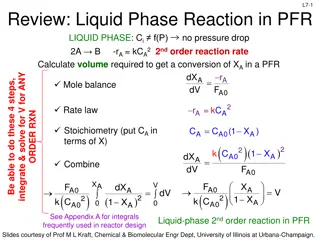
L3-3 Review: Molar Balance PFR Flow reactor operated at steady state (no accumulation per ) Composition of fluid varies down length of reactor (material balance for differential element of volume V V FA0 FA dNj rj V - + = Fj0 Fj dt F F lim + j V V V j V = r + = F F r V 0 j j j j V 0 + V V V dF Ideal SS PFR Design Eq. j = r j dV Slides courtesy of Prof M L Kraft, Chemical & Biomolecular Engr Dept, University of Illinois at Urbana-Champaign.
Review: Molar Balance- Packed Bed Reactor (PBR) L3-4 Heterogeneous rxn: reaction occurs at catalyst particle surface Concentration gradient of reactant and product change down length of the reactor Rxn rate based on the mass of catalyst W, not reactor volume V dF Similar to PFR, but expressed in terms of catalyst weight instead of reactor volume j = r j dV mol mol Units for the rate of a homogeneous rxn (rj) : Units for the rate of a catalytic rxn (rj ) : 3 s m s catalyst kg So in terms of catalyst weight instead of reactor volume: dF j j= where ' r W weight the is of catalyst the dW Slides courtesy of Prof M L Kraft, Chemical & Biomolecular Engr Dept, University of Illinois at Urbana-Champaign.
L3-5 L3: Conversion and Reactors in Series FA1, X1 FA1, X1 FA2, X2 FA0 X0 FA0 X0 V2 FA2 X2 V1 V1 V2 FA0/-rA (m3) VCSTR1 VPFR2 XA Slides courtesy of Prof M L Kraft, Chemical & Biomolecular Engr Dept, University of Illinois at Urbana-Champaign.
L3-6 Conversion, XA Conversion is convenient for relating: rj, V, , Nj, Fj, and Cj B b A a + Choose limiting reactant A as basis of calculation and normalize: b A + d + c C D c d + B a C D a a moles reacted A XA conversion based on A moles A fed BATCH SYSTEM: Moles A fed is the amount of A at the start of the reactor (t=0) FLOW SYSTEM: Moles A fed is the amount of A entering the reactor Usually pick the basis to be the limiting reagent Slides courtesy of Prof M L Kraft, Chemical & Biomolecular Engr Dept, University of Illinois at Urbana-Champaign.
L3-7 Conversion Example A + 2B 2C Start with 1 mole of A & 1 mole of B If A is the basis and at the end we have: 1 mole A, 1 mole B mole A, 0 mole B 0 mole A, -1 mole B XA = 0/1 = 0 (no reaction) XA = 0.5/1 = 1/2 XA = 1/1 = 1 (complete reaction) Not possible! The correct approach is to take B as the basis because B is the limiting reagent At the end we have: 1 mole A, 1 mole B XB = 0/1 = 0 (no reaction) mole A, 0 mole B XB = 1/1 = 1 (complete reaction) Slides courtesy of Prof M L Kraft, Chemical & Biomolecular Engr Dept, University of Illinois at Urbana-Champaign.
Expressing other Components in Terms of Conversion of A (XA) D a a a Longer reactant is in reactor, more reactant is converted to product (until reactant is consumed or the reaction reaches equilibrium) Conversion (Xj) is a function of time (t) in the batch reactor N N = L3-8 b c d moles reacted A + + A B C XA moles A fed BATCH SYSTEM: N X A A 0 A 0 A Moles A in reactor at time t Moles A fed Moles A consumed ) A X - = ( = N N 1 A A 0 product reactant b c ( ) ( ) = = + N N N X N N N X B B 0 A 0 A C C ( 0 A 0 A a a d ) ( ) I= N N component inert = + N N N X 0 I D D 0 A 0 A a Slides courtesy of Prof M L Kraft, Chemical & Biomolecular Engr Dept, University of Illinois at Urbana-Champaign.
Expressing other Components in Terms of Conversion of A (XA) d C a a L3-9 b c moles reacted A + + A B D XA moles A fed a d c b = = + + N N N 1 N X j T j T 0 A 0 A a a a Total moles in reactor at time t Total moles fed+ total moles products formed minus reactants consumed = j stoichiometric coefficient; positive for products, negative for reactants b c d = = 1 = = B A c d a a a = + N N N X j 0 j j A 0 A = = + N N N N X j T j T 0 j A 0 A j Slides courtesy of Prof M L Kraft, Chemical & Biomolecular Engr Dept, University of Illinois at Urbana-Champaign.
L3-10 Batch Reactor Design Equation with Xj d C a a b c moles reacted A + + A B D XA moles A fed a = N N N X In terms of A: A A 0 A 0 A dN Ideal Batch Reactor Design Eq: A= r V A dt Want to determine how long to leave reactants in reactor to achieve a desired value for the conversion d N dt dX N dt dX N 0 A = Design Eq with Xj: take derivative of NA equation w/ respect to time dN dX d A A ( ) ( ) = 0 N = N N X A 0 A A 0 A 0 A dt dt dt dN A A = Substitute into batch reactor design eq A 0 dt X A dX A A V Ideal Batch Reactor r V = t N 0 A A 0 dt r A Slides courtesy of Prof M L Kraft, Chemical & Biomolecular Engr Dept, University of Illinois at Urbana-Champaign.
L3-11 Flow and Conversion d C a b c moles reacted A + + XA A B a D a moles A fed For a given flow rate, the larger the reactor, the more time it takes the reactant to pass through the reactor, the more time to react Conversion (Xj) is a function of reactor volume (V) FLOW SYSTEM: = F F F X A A 0 A 0 A Molar flow rate A is fed to reactor ( 0 A F = F : = Molar rate A is consumed in reactor Molar flow rate that A leaves the reactor - = ) F 1 X A A j + general in F F X j 0 j j A 0 A = = + F F F F X j T j T 0 A 0 A j Slides courtesy of Prof M L Kraft, Chemical & Biomolecular Engr Dept, University of Illinois at Urbana-Champaign.
L3-12 CSTR Design Equation & Xj F F A 0 A = V Ideal SS CSTR: r j Substitute for FA = F F F X A A 0 A 0 A ( )( ) F F F X A 0 A 0 A 0 A = V r A F X Ideal CSTR design eq in terms of XA A 0 A = V r A V CSTR volume required to achieve a specified conversion Note: XA and rA are evaluated at the exit of the CSTR Slides courtesy of Prof M L Kraft, Chemical & Biomolecular Engr Dept, University of Illinois at Urbana-Champaign.
L3-13 PFR Design Equation & Xj dF A = r A Ideal SS PRF: dV = F F F X A A 0 A 0 A Want to determine the reactor volume required to achieve a desired amount of conversion ( A 0 A 0 A A X F F dV dV take derivative of FA expression with respect to volume dF dX d d ( ) ) A A = = F F 0 A 0 dV dV dF dX A A = F Substitute into PFR design eq A 0 dV dV X A dX dX A Ideal SS PFR Design Eq with Xj: A = V F = 0 F r A 0 A 0 A r dV A Applies for no pressure drop down PFR! Slides courtesy of Prof M L Kraft, Chemical & Biomolecular Engr Dept, University of Illinois at Urbana-Champaign.
L3-14 PBR Design Equation & Xj dF A= r ' Ideal SS PBF: A dW = F F F X A A 0 A 0 A Want to determine the weight of catalyst that is required to achieve a desired amount of conversion d F dW take derivative of FA expression with respect to W dF dX d A A ( ) ( ) = F 0 = F F X A 0 A A 0 A 0 A dW dW dW dF dX A A = F Substitute into PBR design eq A 0 dW dW dX X A dX A Ideal SS PBR Design Eq with Xj: A = W F = F r ' 0 A 0 A 0 A r ' dW A Applies for no pressure drop down PBR! Slides courtesy of Prof M L Kraft, Chemical & Biomolecular Engr Dept, University of Illinois at Urbana-Champaign.
L3-15 Sizing CSTRs We can determine the volume of the CSTR required to achieve a specific conversion if we know how the reaction rate rj depends on the conversion Xj Ideal SS CSTR design eq. Volume is product of FA0/-rA and XA F X F A 0 A A r 0 = = CSTR V CSTR V X A r A A Plot FA0/-rA vs XA (Levenspiel plot) VCSTR is the rectangle with a base of XA,exit and a height of FA0/-rA Area = Volume of CSTR FA0 rA FA0 rA V = X1 X1 X1 X Slides courtesy of Prof M L Kraft, Chemical & Biomolecular Engr Dept, University of Illinois at Urbana-Champaign.
L3-16 Sizing a CSTR with a Levenspiel Plot XA 0 0.1 1.08 0.2 1.33 0.4 2.05 0.6 3.56 0.7 5.06 0.8 8 FA0/-rA 0.89 VCSTR for XA = 0.4? = 9 8 F A r 0 CSTR V X A 7 A 6 FA0/-rA (m3) 5 Value of FA0/-rA for XA=0.4 4 ( . 2 ) 4 . 0 = CSTR V 05 3 2 3 = . 0 82 m 1 0 VCSTR for XA = 0.8? 0 0.1 0.2 0.3 0.4 0.5 0.6 0.7 0.8 0.9 XA 1 ( ) 8 = CSTR V = 8 . 0 3 4 . 6 m Slides courtesy of Prof M L Kraft, Chemical & Biomolecular Engr Dept, University of Illinois at Urbana-Champaign.
L3-17 Sizing PFRs We can determine the required volume of a PFR to achieve a specific conversion if we know how the reaction rate rj depends on the conversion Xj exit , A X 0 A PFR r design eq. X A exit , F dX Ideal PFR A r 0 A = = dX V F PFR V A A A 0 0 Plot FA0/-rA vs XA (Experimentally determined numerical values) VPFR is the area under the curve FA0/-rA vs XA,exit Area = Volume of PFR FA0 rA dX FA0 rA X1 V = 0 X1 Slides courtesy of Prof M L Kraft, Chemical & Biomolecular Engr Dept, University of Illinois at Urbana-Champaign.
L3-18 Sizing a PFR with a Levenspiel Plot XA 0 0.1 1.08 0.2 1.33 0.4 2.05 0.6 3.56 0.7 5.06 0.8 8 FA0/-rA 0.89 VPFR for XA = 0.4? X A exit , F A r 0 = dX PFR V A A 0 We do not have an expression for rA(XA) Slides courtesy of Prof M L Kraft, Chemical & Biomolecular Engr Dept, University of Illinois at Urbana-Champaign.
L3-19 Sizing a PFR with a Levenspiel Plot XA 0 0.1 1.08 0.2 1.33 0.4 2.05 0.6 3.56 0.7 5.06 0.8 8 FA0/-rA 0.89 VPFR for XA = 0.4? X A exit , F A r 0 = dX PFR V A A 0 We do not have an expression for rA(XA) Numerically evaluate (Appendix A.4) to estimate the area under the curve Volume of PFR Slides courtesy of Prof M L Kraft, Chemical & Biomolecular Engr Dept, University of Illinois at Urbana-Champaign.
L3-20 Numerical Evaluation of Integrals (A.4) Simpson s one-third rule (3-point): 2 X f ( ) ( ) ( ) 1 0 0 2 0 1 X X h = Trapezoidal rule (2-point): 1 X h dx x f = h ( ) x ( ) ( ) ( ) + = + + f X f X dx f X f 4 X f X 0 1 2 3 0 X X 2 0 = = + h X X h 1 0 2 Simpson s three-eights rule (4-point): = + = + X X h X X 2 h 1 0 2 0 X 3 3 3 ( ) x ( ) ( ) ( ) ( ) X X = + + + f dx h f X f 3 X f 3 X f X 0 = h 0 1 2 3 8 3 0 Simpson s five-point quadrature : 0 X f 3 X 4 X X 4 h ( ) x ( ) ( ) ( ) ( ) ( ) 0 = h = + + + + f dx f 4 X f 2 X f 4 X f X 1 2 3 4 4 0 Slides courtesy of Prof M L Kraft, Chemical & Biomolecular Engr Dept, University of Illinois at Urbana-Champaign.
L3-21 Sizing a PFR with a Levenspiel Plot XA XA 0 0 0.1 1.08 1.08 0.1 0.2 1.33 1.33 1.33 0.2 0.4 2.05 2.05 2.05 0.4 0.6 3.56 3.56 0.6 0.7 5.06 5.06 0.7 0.8 0.8 8 8 FA0/-rA FA0/-rA 0.89 0.89 0.89 X VPFR for XA = 0.4? A exit , F A r 0 = dX PFR V A XA increments must be equal A 0 Use Simpson s one-third rule (3-point): X X f 3 4 . 0 h = 2 X X h ( ) x ( ) ( ) ( ) 2 0 = = + = + + h X X h f dx f 4 X f X 1 0 0 1 2 2 0 0 = = 2 . 0 + = 0.2 X 0 2 . 0 1 2 F F X F X h A X A A 0 0 = 0 = V = + + 4 ( ) ( ) ( ) P R F r r 0 2 . r . = 3 0 0 4 A A A . 0 2 3 ( ) 3 V 0 89 . 1 33 . . 0 55 . m = + + = 4 2 05 = area under the curve PFR Slides courtesy of Prof M L Kraft, Chemical & Biomolecular Engr Dept, University of Illinois at Urbana-Champaign.
L3-22 Reactors in Series In practice, reactors are usually connected so the exit stream of one reactor is the feed stream for the next reactor Conversion up to point i (no side streams): total moles of reacted A point to up i Xi= reactor 1st into fed A Moles FA2 i=2 X2 FA1 i=1 X1 V2 FA0 FA3 i=3 X3 V3 V1 = F F F X Ai A 0 A 0 i Slides courtesy of Prof M L Kraft, Chemical & Biomolecular Engr Dept, University of Illinois at Urbana-Champaign.
L3-23 2 CSTRs in Series FA1, X1 Materials balance reactor 1: In Out - + Gen. = Accum. FA0 X0 FA2 X2 + = F F A1 r V 0 A0 A1 1 V1 V2 Need to express FA1 in terms of X1 = F F F X A1 A0 A0 1 ( ) + = F F - F X A1 r V 0 A 0 A0 A 0 1 1 + = F X r V 0 A 0 1 A 1 1 F A 0 = X V 1 CSTR 1 r A 1 Slides courtesy of Prof M L Kraft, Chemical & Biomolecular Engr Dept, University of Illinois at Urbana-Champaign.
L3-24 2 CSTRs in Series Materials balance reactor 2: In Out - + Gen. = Accum. F F 2 A 1 A F V = FA1, X1 FA0 X0 + = r V 0 A 2 2 F FA2 X2 A 1 A 2 CSTR 2 r A 2 V1 V2 Need to express FA2 in terms of X2 Materials balance reactor 1: = F F F X = F F F X A 2 A 0 A 0 2 A 1 A 0 A 0 1 ( ) ( r ) F F F X F F X A 0 = A 0 A 0 1 A 0 A 0 2 X V = CSTR V 1 CSTR 1 2 r A 1 A 2 F ( ) A r 0 = CSTR V X X 2 2 1 A 2 Value of FA0/-rA at X2 Slides courtesy of Prof M L Kraft, Chemical & Biomolecular Engr Dept, University of Illinois at Urbana-Champaign.
L3-25 2 CSTRs in Series FA1, X1=0.4 XA 0 0.4 2.05 0.8 8 FA0/-rA 0.89 FA0 X0 9 8 FA2 7 X2=0.8 6 FA0/-rA (m3) 5 V1 V2 4 VCSTR1 for XA1 = 0.4? ( 1 CSTR . 2 V = VCSTR2 for XA2 = 0.4 to 0.8? F V ( )( 2 CSTR 8 . 0 8 V = = + 3 2 ) 4 . 0 3 = 05 . 0 82 m 1 0 0 0.1 0.2 0.3 0.4 0.5 0.6 0.7 0.8 XA ( ) A r 0 = X X CSTR 2 2 1 A 2 ) 3 VCSTR of single CSTR with XA = 0.8? ( ) CSTR 8 . 0 8 V = < 4 . 0 = 2 . 3 m 3 3 3 3 = 2 . 3 + = 4 . 6 m CSTR V . 0 82 m m . 4 02 m 1 2 Usually for the same overall conversion, VTOTAL, 2 CSTRsIN SERIES < VSINGLE CSTR Slides courtesy of Prof M L Kraft, Chemical & Biomolecular Engr Dept, University of Illinois at Urbana-Champaign.
L3-26 2 PFRs in Series FA1 X1 FA0, X0 FA2, X2 X X X 2 1 2 F F 2 PFRs in series, X1=0.4 and X2=0.8 F A r 0 A r 0 A r 0 = dX 0.6 0.8 dX + dX PFR V A A A A A A 0 0 X 1 XA 0 0.2 0.4 FA0/-rA0.89 1.33 2.05 3.56 When XA1= 0.4, VPFR1 =0.55 m3 (slide L3-20) 8 VPFR2 for XA2 = 0.4 to 0.8? F 0 A h 4 F F A 0 A 0 = + + V ) ( ) ( ) ( = = = 3 r X 4 . 0 r X 6 . 0 r X 8 . 0 A A A 2 . 0 . 2 ( . 3 ) 3 = + + = PFR V 05 4 56 8 . 3 61 m 2 3 = 3 3 3 . 1 + = PFR V Same volume as 1 PFR with XA=0.8 . 0 55 m 61 m . 2 17 m + 1 2 Slides courtesy of Prof M L Kraft, Chemical & Biomolecular Engr Dept, University of Illinois at Urbana-Champaign.
Combinations of CSTRs & PFRs in Series FA1, X1 FA2, X2 L3-27 FA1 X1 FA2, X2 FA0, X0 FA0 X0 V1 V2 V2 V1 VCSTR1 VPFR2 VPFR1 VCSTR2 ( ) VCSTR1+ VPFR2 VPFR1 + CCSTR2 Slides courtesy of Prof M L Kraft, Chemical & Biomolecular Engr Dept, University of Illinois at Urbana-Champaign.
L3-28 Reactors in Series F If A ) i ( PFR PFR one V V A0 monotonica is increasing lly then , r - + one V CSTR V ) j ( CSTR i j for any combination of PFRs & CSTRs in series In general, 1 PFR = any number of PFRs in series 1 PFR = number of CSTRs in series Definitions: Space time ( ): time necessary to process one reactor volume, also called mean residence time or holding time V = 0 V 1 Space velocity (SV): inverse of space time, but vo may be measured under different conditions than the space time Liquid-hourly space velocity 0| is the volumetric flow rate measured at specified condition 0= = SV Gas-hourly space velocity 0 liquid@ 60 F or 75 F V 0 STP V = = GHSV LHSV Slides courtesy of Prof M L Kraft, Chemical & Biomolecular Engr Dept, University of Illinois at Urbana-Champaign.