The Inversion of Mechanisms in Kinematics
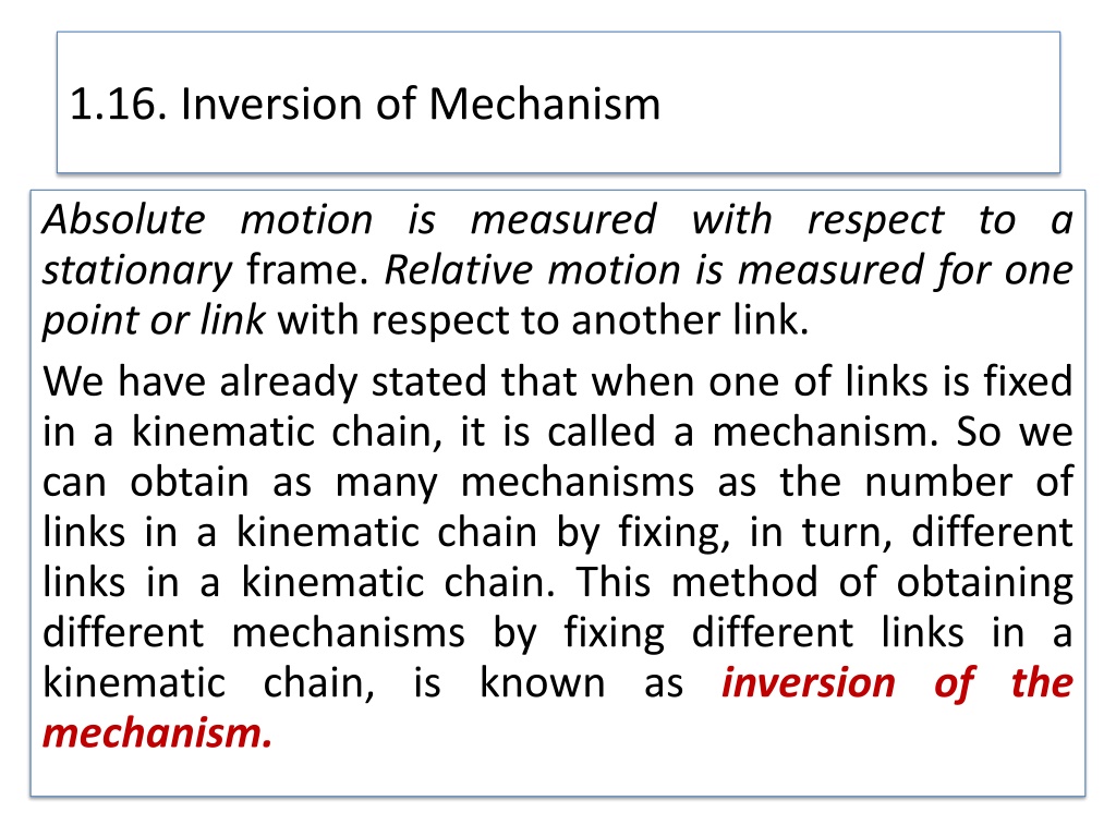
1.16. Inversion of Mechanism
Absolute motion is measured with respect to a
stationary
frame.
Relative motion is measured for one
point or link
with respect to another link.
We have already
stated
that when one of links is fixed
in a kinematic chain, it is called a
mechanism. So we
can obtain as many mechanisms as the number of
links in a kinematic chain by
fixing, in turn, different
links in a kinematic chain. This method of obtaining
different mechanisms by
fixing different links in a
kinematic chain, is known as
inversion of the
mechanism.
It may be noted that the relative motions
between the various links is not changed in
any
manner through the process of inversion,
but their absolute motions (those measured
with respect to
the fixed link) may be changed
drastically.
1.16. Inversion of Mechanism
Note:
The part of a mechanism which initially moves with
respect to the frame or fixed link is called
driver
and
that part of the mechanism to which motion is
transmitted is called
follower.
Most of the mechanisms are
reversible, so that same
link can play the role of a driver and follower at
different times. For example, in a
reciprocating steam
engine, the piston is the driver and flywheel is a
follower while in a reciprocating air
compressor, the
flywheel is a driver.
1.16. Inversion of Mechanism
The most important kinematic chains are those
which consist of four lower pairs, each pair
being a
sliding pair or a turning pair. The following three
types of kinematic chains with four lower
pairs are
important from the subject point of view :
1. Four bar chain or quadric cyclic chain,
2. Single slider crank chain,
3. Double slider crank chain.
These kinematic chains are discussed, in detail, in the
following articles.
1.16. Inversion of Mechanism
1.16. Inversion of Mechanism
1.
Four Bar Chain or Quadric Cycle Chain
We have already discussed that the kinematic chain is a combination of
four or more
kinematic pairs, such that the relative motion between the
links or elements is completely constrained.
The simplest and the basic kinematic chain is a four
-
bar chain or
q
uadric
cycle chain, as shown in Fig.
1
.
32
.
https://youtu.be/KBFFwgCCP0U
https://youtu.be/0neC37jBxQw
https://youtu.be/uvJjFgRqSTg
Fig. 1.32 Four bar chain
It consists of four links, each of
them forms a turning pair at
A, B, C and D.
The four links may be of
different lengths.
In a four
bar chain, one of the links, in particular the
shortest link, will make a complete revolution relative to
the other three links, if it satisfies the Grashof ’s law. Such
a link is known as
crank or driver
.
In
Fig.
1
.
32
,
AD (link 4 ) is
a crank
. The link BC (link 2)
which makes a partial rotation or oscillates is known
as
lever or rocker or follower
and the link CD (link 3) which
connects the crank and lever is called
connecting rod or
coupler.
The fixed link AB (link 1) is known as
frame
of
the mechanism.
When the crank (link 4) is the driver, the mechanism is
transforming rotary motion into
oscillating motion.
1.16. Inversion of Mechanism
A very important consideration in designing a mechanism is to
ensure that the input crank makes a complete revolution relative to
the
other links. The mechanism in which no link makes a complete
revolution will not be useful
in such applications. For the four-bar
linkage there is a very simple test of whether this is the case.
Grashof’s law for four-bar mechanism.
If one of the links can perform a full rotation
relative to another
link, the linkage is called a
Grashof mechanism.
Grashof’s law
states that
for a planar four-bar mechanism (linkage), the sum of
the shortest and longest link lengths
can not be greather
than the
sum of the other two link lengths if there is to be continuous
relative motion between two member
s.
This is illustrated in Fig. 1.33, where the longest link has length
l
, the shortest
link has length
s
, and the other two links have lengths
p
and
q
. Grashof’s law
states that one of the links , in particular the shortest link, will rotate
continuously relative to the other three links if only if
or
where L
max
and L
min
are the longest and shortest links, L
a
and L
b
are each links
of intermediate length. If this ınequalıty is not satisfied no link will make a
complete revolution relative to another.
1.16. Inversion of Mechanism
<
https://youtu.be/eojqAbhdg_w
Fig. 1.33. Four inversions of the Grashof chain
a)
b)
c)
d)
https://youtu.be/9D0IBiM4_1M
https://youtu.be/mwPIB89V-L8
https://
youtu.be/Tjr2c4d09wQ
It should be notted that nothing in Grashof’s law specifies the
order in which the links are connected or which link of the
four –bar chain is fixed. Hence, by fixing any of the four links,
we create four inversions of the four –bar mechanism shown
in Fig.1.33.
The
drag-link
mechanism is obtained by fixing the shortest
link
s
as the frame, as shown in Fig. 1.33a. In this inversion,
both links adjacent to s can rotate continously, and both are
properly described as cranks: the shortest of the two is
generally used as the input
If the shortest links is adjacent to the fixed link, as shown in
Figs.1.33b, a
crank-rocke
r
mechanism
is obtained. Link
s
, the
crank, since it is able to rotate continously , and link
p
, which
can only oscilate between limits, is the rocker.
By fixing the link opposite to s we obtain the the third
inversion, the
double-rocker
mechanism of Fig. 1.33c. Note
that although link s is able to make a complete revolution ,
neither link adjacent to the frame can do so; both must
oscilate between limits and are therefore rockers.
If i.e. or s=p and l=q then, the forth
inversion, the
parallelogram
or
change-point
or
crossover-
position
mechanism
is optained as shown in Fig.1.33d.
In each of these inversions , the shortest link
s
is adjacent to
the longest link
l
. However, exactly the same types of linkages
inversions will occur if the longest link
l
is opposite the
shortest links.
AI-
Inversions of Four Bar Chain
Though there are many inversions of the four bar
chain, yet the following are important from the
subject
point of view :
1.
Beam engine (crank and lever
(rocker)
mechanism).
2.
Coupling rod of a locomotive (Double crank
mechanism).
3.
Watt’s indicator mechanism (Double
lever
(rocker)
mechanism).
1.16. Inversion of Mechanism
1
. Beam engine (crank and lever
(rocker)
mechanism
https://youtu.be/1e8ZWsOzun4
A part of the mechanism of a beam engine (also known as
crank and lever
mechanism) which consists of four links,
is shown in Fig
s
.
1
.
34 and 1.35 .
Fig. 1.34 Beam engine Fig.1.35 Beam engine mechanism
In this mechanism, when the crank
rotates about the fixed centre
A, the lever
oscillates about
a fixed centre
D. The end E of the lever CDE is
connected to a
piston rod which reciprocates due to the
rotation of the crank. In other
words, the purpose of this
mechanism is to convert rotary motion into
reciprocating
motion.
1.16. Inversion of Mechanism
https://
youtu.be/bmh0a2Ol0u8
2.
Coupling rod of a locomotive (Double crank mechanism).
The mechanism of a coupling
rod of a locomotive (also known as double crank
mechanism) which consists of four links, is shown
in Fig. 1.36.
https://youtu.be/gYmT1M4NyyM
Fig. 1.36. Coupling rod of a locomotive
In this mechanism, the links
AD and BC (having equal length) act as cranks and are
connected
to the respective wheels. The link
CD acts as a coupling rod and the link AB
is fixed in order
to maintain a constant centre to centre distance between them.
This mechanism is
used
for transmitting
rotary motion from one wheel to the other
wheel.
1.16. Inversion of Mechanism
3.
Watt’s indicator (Double
rocker)
mechanism.
A Watt’s indicator mechanism
(also known as Watt's straight line mechanism or double lever mechanism) which
consists of four
links, is shown in Fig.
1
.
37
.
Fig.1.37. Watt’s indicator mechanism
The four links are : fixed link
at
A, link AC, link CE and link BFD. It may be noted that
BF and FD form
one link because these two parts have no
relative motion between them. The links
CE and BFD act
as
levers. The displacement of the link
BFD is directly
proportional
to the pressure of gas or steam which
acts on
the indicator plunger. On any small displacement of the
mechanism, the tracing point
E at the
end of the link CE
traces out
approximately
a straight line.
The initial position of the mechanism is shown in
Fig.
1
.
37
by full lines whereas the dotted lines
show the
position of the mechanism when the gas or steam pressure
acts on the indicator plunger.
1.16. Inversion of Mechanism
B. Single Slider Crank Chain
A single slider crank chain is a modification of the basic four bar chain.
It consist of one
sliding pair and three turning pairs. It is,
usually, found
in reciprocating steam engine mechanism.
This type of mechanism
converts rotary motion into reciprocating motion and vice versa.
Fig. 1.38. Single slider crank chain
1.16. Inversion of Mechanism
In a single slider crank chain, as shown in Fig.
1
.
38
,
the links 1 and 2, links 2 and 3, and links
3 and 4
form three turning pairs while the links 4 and 1 form
a sliding pair.
The link 1 corresponds to the frame of the engine,
which is fixed. The link 2 corresponds to
the crank ;
link 3 corresponds to the connecting rod and link 4
corresponds to cross-head. As the
crank rotates, the
cross-head reciprocates in the guides and thus the
piston reciprocates in the
cylinder.
1.16. Inversion of Mechanism
BI:
Inversions of Single Slider Crank Chain
We have seen in the previous article that a single
slider crank chain is a four-link mechanism.
We know
that by fixing, in turn, different links in a kinematic
chain, an inversion is obtained and
we can obtain as
many mechanisms as the links in a kinematic chain. It
is thus obvious, that four
inversions of a single slider
crank chain are possible. These inversions are found
in the following
mechanisms.
1.16. Inversion of Mechanism
1.
Pendulum pump or Bull engine.
In this mechanism, the inversion is obtained by fixing
the
cylinder or link 4 (
i.e. sliding pair), as shown in Fig.
1
.
39
. In this case, when the crank (link 2) rotates,
the
connecting rod (link 3) oscillates about a pin pivoted
to the fixed link 4 at
A and the piston
attached to the
piston rod (link 1) reciprocates. The duplex pump
which is used to supply feed water
to boilers have two
pistons attached to link 1, as shown in Fig.
1
.
39
.
1.16. Inversion of Mechanism
Fig. 1.39 Pendulum pump
1.16. Inversion of Mechanism
https://youtu.be/mxgPTsXpB6k
2.
Oscillating cylinder engine
.
The arrangement
of oscillating cylinder engine
mechanism,
as shown in Fig.
1
.
40
, is used to convert
reciprocating motion
into rotary motion. In this
mechanism, the link 3 forming the turning pair is
fixed. The link 3 corresponds to the connecting
rod of a reciprocating steam
engine mechanism.
When the crank (link 2) rotates, the piston attached
to
piston rod (link 1) reciprocates and the
cylinder (link 4) oscillates about a pin
pivoted to
the fixed link at
A.
https://youtu.be/cz4tCwwvvDM
Fig.1.40 Oscilating cylinder engine
1.16. Inversion of Mechanism
3.
Rotary internal combustion engine
or Gnome engine.
Sometimes back, rotary internal
combustion engines
were used in aviation.
But
presently
gas turbines are
used in its place.
It consists of seven cylinders in one
plane and
all revolves about fixed centre
D, as shown in
Fig.
1
.
41
, while the crank (link 2) is fixed. In
this
mechanism, when the connecting rod (link
4) rotates,
the piston (link 3) reciprocates inside
the cylinders
forming link 1.
1.16. Inversion of Mechanism
Fig. 1.41
1.16. Inversion of Mechanism
https://youtu.be/W3elogQimk4
https://youtu.be/0jHRuEkvO8E
4.
Crank and slotted lever quick return motion mechanism
.
This
mechanism is mostly used
in shaping machines, slotting
machines and in rotary internal combustion engines.
Fig.1.42
1.16. Inversion of Mechanism
https://youtu.be/s3TiMedJKds
https://youtu.be/ESBYdJx8X7k
In this mechanism, the link
AC (i.e. link 3) forming the turning
pair is fixed, as shown in Fig.
1
.
42
. The link 3 corresponds to the
connecting rod of a reciprocating steam engine. The driving
crank
CB revolves with uniform angular speed about the fixed
centre C. A sliding block attached to the crank
pin at
B slides
along the slotted bar AP and thus causes AP to oscillate about
the pivoted point A. A
short link
PR transmits the motion from AP
to the ram which carries the tool and reciprocates along the
line
of stroke
R1R2. The line of stroke of the ram (i.e. R1R2) is
perpendicular to AC produced.
1.16. Inversion of Mechanism
5.
Whitworth quick return motion mechanism.
Fig. 1.43
https://youtu.be/UuTNtg7-Bwg
1.16. Inversion of Mechanism
Whitworth quick return motion mechanism
This mechanism is mostly used in shaping
and slotting machines. In this
mechanism, the link
CD (link 2) forming the
turning pair is fixed, as
shown in
Fig.
1
.
43
. The link 2
corresponds to a crank in a reciprocating steam engine.
The driving
crank
CA (link 3) rotates at a uniform angular speed. The slider
(link 4) attached to the crank pin at A
slides along the slotted bar
PA (link 1)
which oscillates at a pivoted point D. The connecting rod PR
carries the ram at
R to which a cutting tool is fixed. The motion of the tool is constrained along
the
line
RD produced, i.e. along a line passing through D and perpendicular to
CD.
1.16. Inversion of Mechanism
When the driving crank
CA moves from the position CA1 to CA2 (or
the link DP from the
position
DP1 to
DP2) through an angle α in the
clockwise direction,
the tool moves from the left hand
end of its
stroke
to the right hand end through a distance 2
PD.
Now when the
driving crank moves from the position
CA2 to CA1 (or the link DP from
DP2 to
DP1 ) through an angle β in the clockwise direction, the tool
moves back from right hand end of its
stroke to the left hand end.
A little consideration will show that the time taken during the left to
right movement of the
ram (
i.e. during forward or cutting stroke) will
be equal to the time taken by the driving crank to move
from
CA1 to
CA2. Similarly, the time taken during the right to left movement of the
ram (or during the
idle or return stroke) will be equal to the time
taken by the driving crank to move from
CA2 to CA1.
1.16. Inversion of Mechanism
Since the crank link
CA rotates at uniform angular velocity
therefore time taken during the
cutting stroke (or forward
stroke) is more than the time taken during the return
stroke. In other words,
the mean speed of the ram during
cutting stroke is less than the mean speed during the return
stroke.
The ratio between the time taken during the cutting
and return strokes is given by
Time of cutting stroke
/
Time of return stroke
=
α
/
β =α
/( 360
°
-
α
) or
=
(360
°− β
)/
β
Note. In order to find the length of effective stroke
R1 R2,
mark P1 R1 = P2 R2 = PR. The length of effective
stroke is
also equal to 2
PD.
1.16. Inversion of Mechanism
C-Double Slider Crank Chain
A kinematic chain which consists of two turning pairs
and two sliding pairs is known as
double slider crank
chain, as shown in Fig.
1
.
44
. We see that the link 2 and
link 1 form one turning
pair and link 2 and link 3 form
the second turning pair. The link 3 and link 4 form one
sliding pair and
link 1 and link 4 form the second sliding
pair.
https://youtu.be/iMYiM8I__vE
1.16. Inversion of Mechanism
C.
Inversions of Double Slider Crank Chain
The following three inversions of a double slider crank chai
n
Are important from the subject point of view:
1.
Elliptical trammels.
It is an instrument used for
drawing ellipses. This inversion is obtained
by fixing
the slotted plate (link 4), as shown in Fig.
1
.
44
. The
fixed plate or link 4 has two straight
grooves cut in
it, at right angles to each other. The link 1 and link
3, are known as sliders and form sliding
pairs with
link 4. The link
AB (link 2) is a bar which forms
turning pair
s
with links 1 and 3.
https://youtu.be/dilOGtjHvCE
1.16. Inversion of Mechanism
Fig.1.44 Eliptical trammels
1.16. Inversion of Mechanism
When the links 1 and 3 slide along their respective grooves, any
point on the link 2 such as
P traces out an ellipse on the surface
of link 4, as shown in Fig.
1
.
44
(a). A little consideration will
show
that
AP and BP are the semi-major axis and semi-minor axis of
the ellipse
r
espectively.
1.16. Inversion of Mechanism
2.
Scotch yoke mechanism.
https://youtu.be/hsaoTo1vuY4
https://youtu.be/HhX-
8RyP214
This mechanism is used for converting rotary
motion into a
reciprocating motion. The inversion is
obtained by fixing either the link 1 or link 3. In Fig.
1
.
45
, link
1 is fixed. In this mechanism, when the
link 2 (which
corresponds to crank) rotates about
B
as centre, the link
4 (which corresponds to a frame)
reciprocates. The fixed
link 1 guides the frame.
1.16. Inversion of Mechanism
Fig 1.45
Scotch yoke mechanism.
1.16. Inversion of Mechanism
3.
Oldham’s coupling.
https://youtu.be/XvaDAbdZCyU
An
O
ldham's coupling is
used for connecting two parallel shafts
whose axes are
at a small distance apart. The shafts are
coupled in
such
a way that if one shaft rotates, the other shaft also
rotates
at
the same speed. This inversion is obtained by fixing
the link 2, as
shown in Fig.
1
.
46
(
a). The shafts to be
connected have two
f
langes
(link 1 and link 3) rigidly
fastened at their ends by forging.
The link 1 and link 3 form turning pairs with link 2. These flanges
have diametrical slots cut
in their inner faces, as shown in Fig.
1
.
46
(
b). The intermediate piece (link 4) which is a circular disc,
have two
tongues (
i.e. diametrical projections) T1 and T2 on each face at right
angles to each other, as
shown in Fig.
1
.
46
(
c). The tongues on the
link 4 closely fit into the slots in the two flanges (link 1 and
link 3).
The link 4 can slide or reciprocate in the slots in the flanges.
1.16. Inversion of Mechanism
Fig. 1.46 Oldham’s coupling.
1.16. Inversion of Mechanism
When the driving shaft
A is rotated, the flange C
(link 1) causes the intermediate piece (link
4) to
rotate at the same angle through which the flange
has rotated, and it further rotates the flange
D
(link
3) at the same angle and thus the shaft
B rotates.
Hence links 1, 3 and 4 have the same angular
velocity at every instant. A little consideration will
show, that there is a sliding motion between the
link 4 and each of the other links 1 and 3.
1.16. Inversion of Mechanism
If the distance between the axes of the shafts is constant,
the centre of intermediate piece will
describe a circle of
radius equal to the distance between the axes of the two
shafts. Therefore, the
maximum sliding speed of each
tongue along its slot is equal to the peripheral velocity of
the centre
of the disc along its circular path.
Let ω = Angular velocity of each shaft in rad/s, and
r = Distance between the axes of the shafts in metres.
∴
Maximum sliding speed of each tongue (in m/s),
v =
ω.
r
1.16. Inversion of Mechanism
Non Grashof mechanisms
Four bar linkages that do not satisfy the Grashof criterion are
called double rocker mechanisms of the second kind or triple-
rocker mechanisms. If L
max
+ L
min
>L
p
+L
q
no link can rotate
through 360
o
. A computer program based on the flowchart
of Figure 1.47 may be used to classify four-bar linkages by
characteristics of their motion.
1.16. Inversion of Mechanism
FIGURE
1.
47
Flowchat for classifying
four-bar linkages accord
ing to the characteristics
of theirmotion.
HOMEWORK
PROBLEM 1
The Grashof Criterion
This problem concerns the classification of four-bar linkages. Link
lengths: L
0
, fixed link; L
1
,
driver crank;
L
2
, coupler; L
3
, follower
crank; L
1
= 100 mm, L
2
= 200 mm, L
3
= 300 mm. Find the ranges of
values for L
0
, if the linkage can be
classified as follows:
a. Grashof mechanism
b.
Crank-rocker mechanis
m
c.
Drag link mechanism
d.
Double-rocker mechanism
e.
Change –point mechanism
f.
Triple-rocker mechanism
Mechanical advantage.
Mechanical advantage of a linkage is the
ratio of output torque exerted by the driven link to the necessary
input torque required at the driver. The mechanical advantage
of the four-bar linkage shown inFig. 1. 48 is directly proportional
to the sine of the angle
γ
between the coupler and the follower
and inversly proportional to the sine of the angle
β
between the
coupler and the driver. When the sign of the angle
β
becomes
zero , the mechanical advantage becomes infinite; thus, at such a
position , only a small imput torque is necessary to overcome a
large output torque load. This is the case when the driver AB of
Fig. 1.48 is directly in line with the coupler BC; it occurs when the
crank is in position AB
1
and again when the crank is in position
AB
4
. Note that these also difine extreme positions of travel of
the rocker DC
1
and DC
4
.When the four-bar linkage is in either of
these positions, mechanical advantage is infinite and the linkage
is said to be in a
toggle
position
.
1.17. Mechanical Advantage
Fig.1.48 Toggle positions
1.17. Mechanical Advantage
Φ
Transmission angle
: The angle
γ
between the coupler
and the follower is called
transmission angle
. As this
angle becomes small, the mechanical advantage
decreases and even a small amount of friction will cause
the mechanism to lock or jam. A common rule of thumb
is that a four- bar linkage should not be used in the rigion
where the transmission angle is less than 40
o
or 45
o
and
no great than 135
o
or 140
o
is usually satisfactory. The
extreme values of the transmission angle occur when the
crank AB lies along the line of the frame AD. In Fig.1.47
the transmission angle is minimum when the crank is
position AB
2
and maximum when the crank has position
AB
3
.
1.17. Mechanical Advantage
Consider the four-bar linkage whose links form a quadrilateral, as
in Figure 1.
49. For crank angle
Using the law of cosines for the triangle formed by the
diagonal and links 2 and 3
FIGURE 1.
49
Determination of transmission angle.
HOMEWORK PROBLEM 2
In order to operate a mechanism, an actuator, or driver
device, is required to provide the input
motion and energy.
To precisely operate a mechanism, one driver is required
for
each degree of freedom exhibited. Many different
actuators
are used in industrial and commercial machines
and mechanisms.
Some of the more common ones are
given
in the following section.
1.18. Actuators and Drivers
Electric motors (DC)
produce continuous rotary
motion. The speed and direction of the motion
can
be readily altered, but they require power
from a generator
or a battery. DC motors can
achieve extremely
high speeds––up to 30,000
rpm. These motors are
most often used in
vehicles, cordless devices, or in
applications
where multiple speeds and directional
control
are required
.
1.18. Actuators and Drivers
Engines
also generate continuous rotary motion.
The
speed of an engine can be throttled within a
range
of approximately 1000 to 8000 rpm. They
are a
popular and highly portable driver for
high-power
applications. Because they rely on
the combustion
of fuel, engines are used to
drive machines that
operate outdoors.
1.18. Actuators and Drivers
Servomotors
are motors that are coupled with a
controller
to produce a programmed motion or
hold a
fixed position. The controller requires
sensors on the
link being moved to provide
feedback information on
its position, velocity,
and acceleration. These motors
have lower
power capacity than non
servomotors and
are
significantly more expensive, but they can be
used
for machines demanding precisely guided
motion,
such as robots.
1.18. Actuators and Drivers
Electric motors (AC)
provide the least expensive
way
to generate continuous rotary motion.
However,
they are limited to a few standard
speeds that are a
function of the electric line
frequency. Single-phase motors are used in
residential
applications and are available from.
Three-phase motors are more efficient, but
mostly limited to industrial applications because
they require three-phase power service.
1.18. Actuators and Drivers
Air or hydraulic motors
also produce continuous
rotary motion and are similar to electric motors,
but
have more limited applications. This is due to
the
need for compressed air or a hydraulic
source. These
drive devices are mostly used
within machines, such
as construction
e
quipment
and aircraft, where high
pressure
hydraulic fluid
is available.
1.18. Actuators and Drivers
Hydraulic or pneumatic cylinders
are common
components
used to drive a mechanism with a
limited
linear stroke. Figure 1.
50
a illustrates a
hydraulic
cylinder. Figure 1.
50
b shows the common
kinematic
representation for the cylinder unit.
The
cylinder unit contains a rod and piston assembly
that slides relative to a cylinder. For kinematic
purposes,
these are two links (piston/rod and
cylinder),
connected with a sliding joint. In addition,
the
cylinder and rod end usually have provisions for
pin
joints.
1.18. Actuators and Drivers
Fig. 1.50 Hydrolic cylinder
1.18. Actuators and Drivers
Screw actuators
also produce a limited linear
stroke
.
These actuators consist of a motor, rotating
a screw.
A
mating nut provides the linear motion.
Screw actuators
can be accurately controlled and
can directly
replace cylinders. However, they are
considerably
more expensive than cylinders if air or
hydraulic
sources are available. Similar to cylinders,
screw actuators
also have provisions for pin joints
at the two
ends. Therefore, the kinematic diagram
is identical to
Figure 1.50b.
1.18. Actuators and Drivers
Manual,
or hand-operated, mechanisms
comprise a large
number of machines, or hand
tools. The motions
expected from human
“actuators” can be quite complex.
However, if
the expected motions are repetitive,
caution
should be taken against possible fatigue and
stain injuries
1.18. Actuators and Drivers
Example 1.10:
Figure 1.
51
shows an outrigger
foot to stabilize a utility truck. Draw a kinematic
diagram, using the bottom of the stabilizing
foot
as a point of interest. Also compute the degrees
of freedom.
Fig. 1.51 Outrigger foot
1.18. Actuators and Drivers
SOLUTION:
1.
Identify the Frame
During operation of the outriggers, the utility truck is
stationary. Therefore, the truck is designated
as the
frame. The motion of all other links is determined relative
to the truck. The frame is numbered as
link 1.
2.
Identify All Other Links
Careful observation reveals three other moving parts:
Link 2: Outrigger leg
Link 3: Cylinder
Link 4: Piston/rod
1.18. Actuators and Drivers
3.
Identify the Joints
Three pin joints are used to connect these different
parts. One connects the outrigger leg with the truck
frame.
This is labeled as joint
A. Another connects the
outrigger leg with the cylinder rod and is labeled as
joint B. The
last pin joint connects the cylinder to the
truck frame and is labeled as joint
C.
One sliding joint
is present in the cylinder unit. This connects the
piston/rod with the cylinder. It is labeled
as joint
D.
4.
Identify Any Points of Interest
The stabilizer foot is part of link 2, and a point of interest located
on the bottom of the foot is
labeled as point of
interest
X.
5.
Draw the Kinematic Diagram
The resulting kinematic diagram is given in
Figure 1.
52.
Fig. 1.52 Kinematic Diagram
1.18. Actuators and Drivers
6.
Calculate Mobility
To calculate the mobility, it was determined that there are four links in
this mechanism, as well as three pin joints
and one slider joint.
Therefore,
l
= 4, jp = (3 pins + 1 slider) = 4, jh = 0
and
n
= 3(n - 1) - 2jp - jh = 3(4 - 1) - 2(4) - 0 = 1
With one degree of freedom, the outrigger mechanism is constrained.
Moving only one link, the piston,
precisely positions all other links in
the outrigger, placing the stabilizing foot on the ground.
1.18. Actuators and Drivers
1. Eccentric Crank
On many mechanisms, the required length of a crank is
so
short that it is not feasible to fit suitably sized bearings
at the
two pin joints. A
common solution is to design the
link as an
eccentric crankshaft, as shown in
Fig
.
1.
53
a.
This is the
design used in most engines and compressors.
The pin, on the moving end of the link, is enlarged
such
that it contains the entire link. The outside circumference
of the circular lobe on the crankshaft becomes the
moving pin joint, as shown in Figure 1.
53
b. The location
of
the fixed bearing, or bearings, is offset from the
eccentric
lobe. This eccentricity of the crankshaft, , is the
effective
length of the crank. Fig
.
1.
53
c illustrates a
kinematic
model of the eccentric crank. The advantage of
the eccentric
crank is the large surface area of the
moving pin, which
reduces wear.
Fig.1.53 Eccentric crank.
2. Pin-in-a-Slot Joint
A common connection between links is a pin-in-a-slot
joint, as shown in Figure 1.
54
a. This is a higher-order joint
because it permits the two links to rotate and slide
relative
to each other. To simplify the kinematic analysis,
primary
joints can be used to model this higher-order
joint. The
pin-in-a-slot joint becomes a combination of a
pin joint
and a sliding
joint, as in Figure 1.
54
b. Note that
this
involves adding an extra link to the mechanism. In
both
cases, the relative motion between the links is the
same.
However, using a kinematic model with primary
joints
facilitates the analysis.
Fig.1.54 Pin-in-a-slot joint.
3. Screw Joint
A screw joint, as shown in Figure 1.
55
a, is another common
c
onnection between links. To start with, a screw joint permits
two relative, but dependent,
m
otions between the links being
joined. A specific rotation of one link will
cause an associated
relative translation between the two links. For
e
xample,
turning the screw one revolution may move the nut along
the
screw threads a distance of 0.1 in. Thus, only one independent
motion is introduced.
A screw joint is typically modeled with a
sliding joint, as
shown in Figure 1.
55
b. It must be understood
that out-of
plane
rotation occurs. However, only the relative
translation
between the screw and nut is considered in planar
kinematic
analysis.
Fig.1.55 Screw joint.
Example 1
.
Figure 1.
56
presents a lift table used to
adjust the working height of different objects. Draw
a kinematic diagram and
compute the degrees of
freedom.
Fig.1. 56 Lift table
Solution:
1.
Identify the Frame:
The bottom base plate rests on a fixed surface. Thus, the base
plate will be designated as the frame. The bearing
at the bottom
right of Figure 1.
56
is bolted to the base plate. Likewise, the two
bearings that support the screw on
the left are bolted to the
base plate.
From the discussion in the previous section, the out-of-plane
rotation of the screw will not be considered.
Only the relative
translation of the nut will be included in the kinematic model.
Therefore, the screw will also
be considered as part of the frame.
The motion of all other links will be determined relative to this
bottom base
plate, which will be numbered as link 1.
2.
Identify All Other Links
Careful observation reveals five other moving parts:
Link 2: Nut
Link 3: Support arm that ties the nut to the table
Link 4: Support arm that ties the fixed bearing to the slot in the
table
Link 5: Table
Link 6: Extra link used to model the pin in slot joint with separate
pin and slider joints
1.19. Commonly Used Lınks and Joınts
3.
Identify the Joints
A sliding joint is used to model the motion between the
screw and the nut. A pin joint, designated as
point
A,
connects the nut to the support arm identified as link 3. A
pin joint, designated as point
B, connects the two support
arms––link 3 and link 4. Another pin joint, designated as
point
C, connects link
4
to link 6. A sliding joint
joins link 6
to the table, link 5. A pin, designated as point
D, connects
the table to the support arm, link 3. Lastly,
a pin joint,
designated as point
E, is used to connect the base to the
support arm, link 4.
Fig.1.57 Kinematic diagram
5.
Draw the Kinematic Diagram
The kinematic diagram is given in Figure 1.
57
.
5.
Calculate Mobility
To calculate the mobility, it was determined that there are six
links in this mechanism. There are also five pin
joints and two
slider joints. Therefore
,
l
= 6
,
jp = (5 pins + 2 sliders) = 7
,
j h = 0
and
n
= 3(
l
- 1) - 2jp - jh = 3(6 - 1) - 2(7) - 0 = 15 - 14 = 1
With one degree of freedom, the lift table has constrained
motion.
Moving one link, the handle that rotates
the screw,
will precisely position all other links in the device, raising or
lowering the table.
There are two different aspects of the study of mechanical
systems:
design
and
analysis.
The concept embodied in the word “ design” might be
more properly termed
syntesis,
the process of contriving a
scheme or a method of accomplising a given purpose.
Design is the process of prescribing the sizes, shapes
material compositions, and arragements of parts so that the
resulting machine will perform the prescribed task. It calls for
imagination, intuition, creativity, judgement and experience.
Design process is by its very nature as much an art as a
science. The role of science in the design process is merely to
provide tools to be used by the designers as that practise their
art.
75
The process of evaluating the various interacting
alternatives that designers find usually requires a large
collection of mathematical and scientific tools. These tools ,
when applied properly , can provide more accurate and
more reliable information for use in judging a design than
one can achive through intuition or estimation. Thus, they
can provide tremendous help in deciding among
alternatives.
Hovever, scientific tools can not make decisions for
designer.
Designers have every right to exert their imaginations
and creative abilities.
The largest collection of scientific methods at the
desgner’s disposal fall into the category called
analysis.
These are the techniques which allow the designer to
critically examine an already existing or proposed design
in order to judge its suitability and rating of things already
conceived.
We should always bear in mind that although most of
our effort may be spent on analysis, real goal is synthesis,
design of a machine or system. Analysis is simply a tool. It
is, however a vital tool and will inevitable be used as one
step in the design process.
REFERENCES
1-
Theory of Machines , by
R.S. Khurmi, J:K. Gupta, Eurasia Publishing House,
2005.
2- Machınes And Mechanısms, Applıed Kınematıc Analysıs, Fourth Edition, by
D. H. Myszka, Prentice Hall, 2012.
3- Kinematics and Dynamics of Machinery, Third Edition in SI Units, by C.E.
Wilson, J.P. Sadler, Pearson, 2006.
4. The Theory of Machines and Mechanisms, J.E.Shigley , J.J.Uicker, Second
Edition, McGraw –Hill, 1995.
5. Internet based resources(Because of the shortage of space, the list is not
given).
Inversion of Mechanisms in Kinematics involves measuring absolute and relative motions in stationary and moving frames, respectively. By fixing different links in a kinematic chain, we can obtain various mechanisms. This process does not alter relative motions but may significantly change absolute motions. The roles of driver and follower in mechanisms are explained, and important kinematic chains with lower pairs are discussed, including the four-bar chain.

Download Presentation

Please find below an Image/Link to download the presentation.
The content on the website is provided AS IS for your information and personal use only. It may not be sold, licensed, or shared on other websites without obtaining consent from the author.If you encounter any issues during the download, it is possible that the publisher has removed the file from their server.
You are allowed to download the files provided on this website for personal or commercial use, subject to the condition that they are used lawfully. All files are the property of their respective owners.
The content on the website is provided AS IS for your information and personal use only. It may not be sold, licensed, or shared on other websites without obtaining consent from the author.
E N D
Presentation Transcript
1.16. Inversion of Mechanism Absolute motion is measured with respect to a stationary frame. Relative motion is measured for one point or link with respect to another link. We have already stated that when one of links is fixed in a kinematic chain, it is called a mechanism. So we can obtain as many mechanisms as the number of links in a kinematic chain by fixing, in turn, different links in a kinematic chain. This method of obtaining different mechanisms by fixing different links in a kinematic chain, is known as inversion of the mechanism.
1.16. Inversion of Mechanism It may be noted that the relative motions between the various links is not changed in any manner through the process of inversion, but their absolute motions (those measured with respect to the fixed link) may be changed drastically.
1.16. Inversion of Mechanism Note: The part of a mechanism which initially moves with respect to the frame or fixed link is called driver and that part of the mechanism to which motion is transmitted is called follower. Most of the mechanisms are reversible, so that same link can play the role of a driver and follower at different times. For example, in a reciprocating steam engine, the piston is the driver and flywheel is a follower while in a reciprocating air compressor, the flywheel is a driver.
1.16. Inversion of Mechanism The most important kinematic chains are those which consist of four lower pairs, each pair being a sliding pair or a turning pair. The following three types of kinematic chains with four lower pairs are important from the subject point of view : 1. Four bar chain or quadric cyclic chain, 2. Single slider crank chain, 3. Double slider crank chain. These kinematic chains are discussed, in detail, in the following articles.
1.16. Inversion of Mechanism 1.Four Bar Chain or Quadric Cycle Chain We have already discussed that the kinematic chain is a combination of four or more kinematic pairs, such that the relative motion between the links or elements is completely constrained. The simplest and the basic kinematic chain is a four- bar chain or quadric cycle chain, as shown in Fig. 1. 32. https://youtu.be/KBFFwgCCP0U https://youtu.be/0neC37jBxQw https://youtu.be/uvJjFgRqSTg Fig. 1.32 Four bar chain It consists of four links, each of them forms a turning pair at A, B, C and D. The four links may be of different lengths.
1.16. Inversion of Mechanism In a four bar chain, one of the links, in particular the shortest link, will make a complete revolution relative to the other three links, if it satisfies the Grashof s law. Such a link is known as crank or driver. In Fig. 1.32, AD (link 4 ) is a crank. The link BC (link 2) which makes a partial rotation or oscillates is known as lever or rocker or follower and the link CD (link 3) which connects the crank and lever is called connecting rod or coupler. The fixed link AB (link 1) is known as frame of the mechanism. When the crank (link 4) is the driver, the mechanism is transforming rotary motion into oscillating motion.
1.16. Inversion of Mechanism A very important consideration in designing a mechanism is to ensure that the input crank makes a complete revolution relative to the other links. The mechanism in which no link makes a complete revolution will not be useful in such applications. For the four-bar linkage there is a very simple test of whether this is the case. Grashof s law for four-bar mechanism. If one of the links can perform a full rotation relative to another link, the linkage is called a Grashof mechanism. Grashof s law states that for a planar four-bar mechanism (linkage), the sum of the shortest and longest link lengths can not be greather than the sum of the other two link lengths if there is to be continuous relative motion between two members.
1.16. Inversion of Mechanism This is illustrated in Fig. 1.33, where the longest link has length l, the shortest link has length s , and the other two links have lengths p and q. Grashof s law states that one of the links , in particular the shortest link, will rotate continuously relative to the other three links if only if or + + L L L L max min a b where Lmax and Lmin are the longest and shortest links, La and Lb are each links of intermediate length. If this nequal ty is not satisfied no link will make a complete revolution relative to another.
1.16. Inversion of Mechanism Fig. 1.33. Four inversions of the Grashof chain c) a) b) d) < https://youtu.be/mwPIB89V-L8 https://youtu.be/9D0IBiM4_1M https://youtu.be/Tjr2c4d09wQ https://youtu.be/eojqAbhdg_w
1.16. Inversion of Mechanism It should be notted that nothing in Grashof s law specifies the order in which the links are connected or which link of the four bar chain is fixed. Hence, by fixing any of the four links, we create four inversions of the four bar mechanism shown in Fig.1.33. The drag-link mechanism is obtained by fixing the shortest link s as the frame, as shown in Fig. 1.33a. In this inversion, both links adjacent to s can rotate continously, and both are properly described as cranks: the shortest of the two is generally used as the input If the shortest links is adjacent to the fixed link, as shown in Figs.1.33b, a crank-rocker mechanismis obtained. Link s, the crank, since it is able to rotate continously , and link p, which can only oscilate between limits, is the rocker.
1.16. Inversion of Mechanism By fixing the link opposite to s we obtain the the third inversion, the double-rocker mechanism of Fig. 1.33c. Note that although link s is able to make a complete revolution , neither link adjacent to the frame can do so; both must oscilate between limits and are therefore rockers. If i.e. or s=p and l=q then, the forth inversion, the parallelogram or change-point or crossover- position mechanism is optained as shown in Fig.1.33d. In each of these inversions , the shortest link s is adjacent to the longest link l . However, exactly the same types of linkages inversions will occur if the longest link l is opposite the shortest links. + + L L Lp Lq max min
1.16. Inversion of Mechanism AI-Inversions of Four Bar Chain Though there are many inversions of the four bar chain, yet the following are important from the subject point of view : 1. Beam engine (crank and lever(rocker) mechanism). 2. Coupling rod of a locomotive (Double crank mechanism). 3. Watt s indicator mechanism (Double lever(rocker) mechanism).
1.16. Inversion of Mechanism 1. Beam engine (crank and lever (rocker) mechanism https://youtu.be/1e8ZWsOzun4 A part of the mechanism of a beam engine (also known as crank and lever mechanism) which consists of four links, is shown in Figs. 1.34 and 1.35 . https://youtu.be/bmh0a2Ol0u8 https://youtu.be/bmh0a2Ol0u8 Fig. 1.34 Beam engine Fig.1.35 Beam engine mechanism In this mechanism, when the crank rotates about the fixed centre A, the lever oscillates about a fixed centre D. The end E of the lever CDE is connected to a piston rod which reciprocates due to the rotation of the crank. In other words, the purpose of this mechanism is to convert rotary motion into reciprocating motion.
1.16. Inversion of Mechanism 2. Coupling rod of a locomotive (Double crank mechanism). The mechanism of a coupling rod of a locomotive (also known as double crank mechanism) which consists of four links, is shown in Fig. 1.36. https://youtu.be/gYmT1M4NyyM Fig. 1.36. Coupling rod of a locomotive In this mechanism, the links AD and BC (having equal length) act as cranks and are connected to the respective wheels. The link CD acts as a coupling rod and the link AB is fixed in order to maintain a constant centre to centre distance between them. This mechanism is used for transmitting rotary motion from one wheel to the other wheel.
1.16. Inversion of Mechanism 3. Watt s indicator (Double rocker) mechanism. A Watt s indicator mechanism (also known as Watt's straight line mechanism or double lever mechanism) which consists of four links, is shown in Fig. 1.37. Fig.1.37. Watt s indicator mechanism The four links are : fixed link at A, link AC, link CE and link BFD. It may be noted that BF and FD form one link because these two parts have no relative motion between them. The links CE and BFD act as levers. The displacement of the link BFD is directly proportional to the pressure of gas or steam which acts on the indicator plunger. On any small displacement of the mechanism, the tracing point E at the end of the link CE traces out approximately a straight line. The initial position of the mechanism is shown in Fig. 1.37 by full lines whereas the dotted lines show the position of the mechanism when the gas or steam pressure acts on the indicator plunger.
1.16. Inversion of Mechanism B. Single Slider Crank Chain A single slider crank chain is a modification of the basic four bar chain. It consist of one sliding pair and three turning pairs. It is, usually, found in reciprocating steam engine mechanism. This type of mechanism converts rotary motion into reciprocating motion and vice versa. Fig. 1.38. Single slider crank chain
1.16. Inversion of Mechanism In a single slider crank chain, as shown in Fig. 1.38, the links 1 and 2, links 2 and 3, and links 3 and 4 form three turning pairs while the links 4 and 1 form a sliding pair. The link 1 corresponds to the frame of the engine, which is fixed. The link 2 corresponds to the crank ; link 3 corresponds to the connecting rod and link 4 corresponds to cross-head. As the crank rotates, the cross-head reciprocates in the guides and thus the piston reciprocates in the cylinder.
1.16. Inversion of Mechanism BI: Inversions of Single Slider Crank Chain We have seen in the previous article that a single slider crank chain is a four-link mechanism. We know that by fixing, in turn, different links in a kinematic chain, an inversion is obtained and we can obtain as many mechanisms as the links in a kinematic chain. It is thus obvious, that four inversions of a single slider crank chain are possible. These inversions are found in the following mechanisms.
1.16. Inversion of Mechanism 1. Pendulum pump or Bull engine. In this mechanism, the inversion is obtained by fixing the cylinder or link 4 (i.e. sliding pair), as shown in Fig. 1.39. In this case, when the crank (link 2) rotates, the connecting rod (link 3) oscillates about a pin pivoted to the fixed link 4 at A and the piston attached to the piston rod (link 1) reciprocates. The duplex pump which is used to supply feed water to boilers have two pistons attached to link 1, as shown in Fig. 1.39.
1.16. Inversion of Mechanism Fig. 1.39 Pendulum pump https://youtu.be/mxgPTsXpB6k
1.16. Inversion of Mechanism 2. Oscillating cylinder engine. The arrangement of oscillating cylinder engine mechanism, as shown in Fig. 1.40, is used to convert reciprocating motion into rotary motion. In this mechanism, the link 3 forming the turning pair is fixed. The link 3 corresponds to the connecting rod of a reciprocating steam engine mechanism. When the crank (link 2) rotates, the piston attached to piston rod (link 1) reciprocates and the cylinder (link 4) oscillates about a pin pivoted to the fixed link at A. https://youtu.be/cz4tCwwvvDM Fig.1.40 Oscilating cylinder engine
1.16. Inversion of Mechanism 3. Rotary internal combustion engine or Gnome engine. Sometimes back, rotary internal combustion engines were used in aviation. But presently gas turbines are used in its place. It consists of seven cylinders in one plane and all revolves about fixed centre D, as shown in Fig. 1.41, while the crank (link 2) is fixed. In this mechanism, when the connecting rod (link 4) rotates, the piston (link 3) reciprocates inside the cylinders forming link 1.
1.16. Inversion of Mechanism http://www.century-of-flight.net/Aviation%20history/airplane%20at%20war/upload2/new%20images/4.gif Fig. 1.41 https://youtu.be/W3elogQimk4 https://youtu.be/0jHRuEkvO8E
1.16. Inversion of Mechanism 4. Crank and slotted lever quick return motion mechanism. This mechanism is mostly used in shaping machines, slotting machines and in rotary internal combustion engines. Fig.1.42 https://youtu.be/ESBYdJx8X7k https://youtu.be/s3TiMedJKds
1.16. Inversion of Mechanism In this mechanism, the link AC (i.e. link 3) forming the turning pair is fixed, as shown in Fig. 1.42. The link 3 corresponds to the connecting rod of a reciprocating steam engine. The driving crank CB revolves with uniform angular speed about the fixed centre C. A sliding block attached to the crank pin at B slides along the slotted bar AP and thus causes AP to oscillate about the pivoted point A. A short link PR transmits the motion from AP to the ram which carries the tool and reciprocates along the line of stroke R1R2. The line of stroke of the ram (i.e. R1R2) is perpendicular to AC produced.
1.16. Inversion of Mechanism Whitworth quick return motion mechanism 5. Whitworth quick return motion mechanism. Fig. 1.43 https://youtu.be/UuTNtg7-Bwg
1.16. Inversion of Mechanism This mechanism is mostly used in shaping and slotting machines. In this mechanism, the link CD (link 2) forming the turning pair is fixed, as shown in Fig. 1.43. The link 2 corresponds to a crank in a reciprocating steam engine. The driving crank CA (link 3) rotates at a uniform angular speed. The slider (link 4) attached to the crank pin at A slides along the slotted bar PA (link 1) which oscillates at a pivoted point D. The connecting rod PR carries the ram at R to which a cutting tool is fixed. The motion of the tool is constrained along the line RD produced, i.e. along a line passing through D and perpendicular to CD.
1.16. Inversion of Mechanism When the driving crank CA moves from the position CA1 to CA2 (or the link DP from the position DP1 to DP2) through an angle in the clockwise direction, the tool moves from the left hand end of its stroke to the right hand end through a distance 2 PD. Now when the driving crank moves from the position CA2 to CA1 (or the link DP from DP2 to DP1 ) through an angle in the clockwise direction, the tool moves back from right hand end of its stroke to the left hand end. A little consideration will show that the time taken during the left to right movement of the ram (i.e. during forward or cutting stroke) will be equal to the time taken by the driving crank to move from CA1 to CA2. Similarly, the time taken during the right to left movement of the ram (or during the idle or return stroke) will be equal to the time taken by the driving crank to move from CA2 to CA1.
1.16. Inversion of Mechanism Since the crank link CA rotates at uniform angular velocity therefore time taken during the cutting stroke (or forward stroke) is more than the time taken during the return stroke. In other words, the mean speed of the ram during cutting stroke is less than the mean speed during the return stroke. The ratio between the time taken during the cutting and return strokes is given by Time of cutting stroke/ Time of return stroke = / = /( 360 - ) or = (360 )/ Note. In order to find the length of effective stroke R1 R2, mark P1 R1 = P2 R2 = PR. The length of effective stroke is also equal to 2 PD.
1.16. Inversion of Mechanism C-Double Slider Crank Chain A kinematic chain which consists of two turning pairs and two sliding pairs is known as double slider crank chain, as shown in Fig. 1.44. We see that the link 2 and link 1 form one turning pair and link 2 and link 3 form the second turning pair. The link 3 and link 4 form one sliding pair and link 1 and link 4 form the second sliding pair. https://youtu.be/iMYiM8I__vE
1.16. Inversion of Mechanism C.Inversions of Double Slider Crank Chain The following three inversions of a double slider crank chain Are important from the subject point of view: 1. Elliptical trammels. It is an instrument used for drawing ellipses. This inversion is obtained by fixing the slotted plate (link 4), as shown in Fig. 1.44. The fixed plate or link 4 has two straight grooves cut in it, at right angles to each other. The link 1 and link 3, are known as sliders and form sliding pairs with link 4. The link AB (link 2) is a bar which forms turning pairs with links 1 and 3. https://youtu.be/dilOGtjHvCE
1.16. Inversion of Mechanism Fig.1.44 Eliptical trammels
1.16. Inversion of Mechanism When the links 1 and 3 slide along their respective grooves, any point on the link 2 such as P traces out an ellipse on the surface of link 4, as shown in Fig. 1.44 (a). A little consideration will show that AP and BP are the semi-major axis and semi-minor axis of the ellipse respectively.
1.16. Inversion of Mechanism 2. Scotch yoke mechanism. https://youtu.be/hsaoTo1vuY4 8RyP214 This mechanism is used for converting rotary motion into a reciprocating motion. The inversion is obtained by fixing either the link 1 or link 3. In Fig. 1.45, link 1 is fixed. In this mechanism, when the link 2 (which corresponds to crank) rotates about B as centre, the link 4 (which corresponds to a frame) reciprocates. The fixed link 1 guides the frame. https://youtu.be/HhX-
1.16. Inversion of Mechanism Fig 1.45 Scotch yoke mechanism.
1.16. Inversion of Mechanism 3. Oldham s coupling. https://youtu.be/XvaDAbdZCyU An Oldham's coupling is used for connecting two parallel shafts whose axes are at a small distance apart. The shafts are coupled in such a way that if one shaft rotates, the other shaft also rotates at the same speed. This inversion is obtained by fixing the link 2, as shown in Fig. 1.46 (a). The shafts to be connected have two flanges (link 1 and link 3) rigidly fastened at their ends by forging. The link 1 and link 3 form turning pairs with link 2. These flanges have diametrical slots cut in their inner faces, as shown in Fig. 1.46 (b). The intermediate piece (link 4) which is a circular disc, have two tongues (i.e. diametrical projections) T1 and T2 on each face at right angles to each other, as shown in Fig. 1.46 (c). The tongues on the link 4 closely fit into the slots in the two flanges (link 1 and link 3). The link 4 can slide or reciprocate in the slots in the flanges.
1.16. Inversion of Mechanism Fig. 1.46 Oldham s coupling.
1.16. Inversion of Mechanism When the driving shaft A is rotated, the flange C (link 1) causes the intermediate piece (link 4) to rotate at the same angle through which the flange has rotated, and it further rotates the flange D (link 3) at the same angle and thus the shaft B rotates. Hence links 1, 3 and 4 have the same angular velocity at every instant. A little consideration will show, that there is a sliding motion between the link 4 and each of the other links 1 and 3.
1.16. Inversion of Mechanism If the distance between the axes of the shafts is constant, the centre of intermediate piece will describe a circle of radius equal to the distance between the axes of the two shafts. Therefore, the maximum sliding speed of each tongue along its slot is equal to the peripheral velocity of the centre of the disc along its circular path. Let = Angular velocity of each shaft in rad/s, and r = Distance between the axes of the shafts in metres. Maximum sliding speed of each tongue (in m/s), v = .r
1.16. Inversion of Mechanism Non Grashof mechanisms Four bar linkages that do not satisfy the Grashof criterion are called double rocker mechanisms of the second kind or triple- rocker mechanisms. If Lmax + Lmin>Lp +Lq no link can rotate through 360o. A computer program based on the flowchart of Figure 1.47 may be used to classify four-bar linkages by characteristics of their motion.
1.16. Inversion of Mechanism FIGURE 1. 47 Flowchat for classifying four-bar linkages accord ing to the characteristics of theirmotion.
HOMEWORK PROBLEM 1 The Grashof Criterion This problem concerns the classification of four-bar linkages. Link lengths: L0, fixed link; L1, driver crank; L2, coupler; L3, follower crank; L1= 100 mm, L2= 200 mm, L3= 300 mm. Find the ranges of values for L0, if the linkage can be classified as follows: a. Grashof mechanism b. Crank-rocker mechanism c. Drag link mechanism d. Double-rocker mechanism e. Change point mechanism f. Triple-rocker mechanism
1.17. Mechanical Advantage Mechanical advantage. Mechanical advantage of a linkage is the ratio of output torque exerted by the driven link to the necessary input torque required at the driver. The mechanical advantage of the four-bar linkage shown inFig. 1. 48 is directly proportional to the sine of the angle between the coupler and the follower and inversly proportional to the sine of the angle between the coupler and the driver. When the sign of the angle becomes zero , the mechanical advantage becomes infinite; thus, at such a position , only a small imput torque is necessary to overcome a large output torque load. This is the case when the driver AB of Fig. 1.48 is directly in line with the coupler BC; it occurs when the crank is in position AB1 and again when the crank is in position AB4. Note that these also difine extreme positions of travel of the rocker DC1 and DC4.When the four-bar linkage is in either of these positions, mechanical advantage is infinite and the linkage is said to be in a toggle position.
1.17. Mechanical Advantage Fig.1.48 Toggle positions
1.17. Mechanical Advantage Transmission angle : The angle between the coupler and the follower is called transmission angle. As this angle becomes small, the mechanical advantage decreases and even a small amount of friction will cause the mechanism to lock or jam. A common rule of thumb is that a four- bar linkage should not be used in the rigion where the transmission angle is less than 40o or 45o and no great than 135o or 140o is usually satisfactory. The extreme values of the transmission angle occur when the crank AB lies along the line of the frame AD. In Fig.1.47 the transmission angle is minimum when the crank is position AB2 and maximum when the crank has position AB3.
1.17. Mechanical Advantage Consider the four-bar linkage whose links form a quadrilateral, as in Figure 1.49. For crank angle 2 + = L L L Ld Using the law of cosines for the triangle formed by the diagonal and links 2 and 3 2 2 0 2 1 cos L 0 1 1 = + 2 2 2 2 3 2 cos Ld L L L L 2 3 FIGURE 1.49 Determination of transmission angle.
HOMEWORK PROBLEM 2 Given the driver crank length L1= 100mm, coupler length L2= 200 mm, and follower length L3= 300 mm, and considering the transmission angle, find the range of values for the fixed link L0if the linkage is to be a crank rocker. Make the design decision to limit the transmission angle to 45 135 .
1.18. Actuators and Drivers In order to operate a mechanism, an actuator, or driver device, is required to provide the input motion and energy. To precisely operate a mechanism, one driver is required for each degree of freedom exhibited. Many different actuators are used in industrial and commercial machines and mechanisms. Some of the more common ones are given in the following section.
1.18. Actuators and Drivers Electric motors (DC) produce continuous rotary motion. The speed and direction of the motion can be readily altered, but they require power from a generator or a battery. DC motors can achieve extremely high speeds up to 30,000 rpm. These motors are most often used in vehicles, cordless devices, or in applications where multiple speeds and directional control are required.
1.18. Actuators and Drivers Engines also generate continuous rotary motion. The speed of an engine can be throttled within a range of approximately 1000 to 8000 rpm. They are a popular and highly portable driver for high-power applications. Because they rely on the combustion of fuel, engines are used to drive machines that operate outdoors.