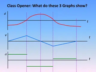
Motion Analysis and Kinematics in Mechanisms
Understanding the concepts of position, displacement, velocity, and acceleration in motion analysis of mechanisms. Exploring the use of loop closure equations to analyze kinematic chains and mechanisms. Introduction to vector quantities in motion analysis and graphical methods for velocity analysis.

Download Presentation

Please find below an Image/Link to download the presentation.
The content on the website is provided AS IS for your information and personal use only. It may not be sold, licensed, or shared on other websites without obtaining consent from the author.If you encounter any issues during the download, it is possible that the publisher has removed the file from their server.
You are allowed to download the files provided on this website for personal or commercial use, subject to the condition that they are used lawfully. All files are the property of their respective owners.
The content on the website is provided AS IS for your information and personal use only. It may not be sold, licensed, or shared on other websites without obtaining consent from the author.
E N D
Presentation Transcript
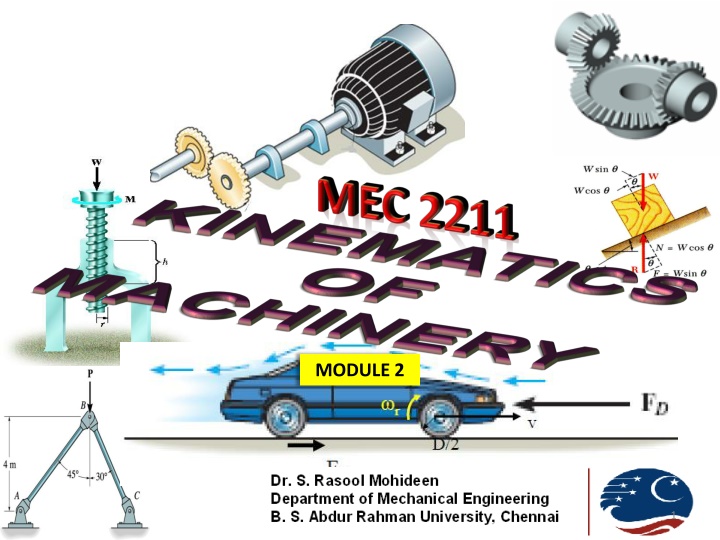
MODULE 2 1
MODULE 2 VELOCITY ANALYSIS 2 Intro Position and Displacement LCE Relative velocity Graphical method Instantaneous centre Method Complex Algebraic Method
Motion Analysis Major Parameters Position with respect to a coordinate system Displacement position difference Velocity- rate change of displacement Acceleration- rate of change of velocity -Rate of change of acceleration ? All are vector quantity
Position Position of an object is defined with respect to a datum This datum is nothing but a coordinate system (CS) Considering a Cartesian coordinate system, Let the point A be at x distance from Y axis and y distance from X axis Point A is positioned at a particular direction (angle) and Magnitude Hence it is represented as vector Position of A with respect to the origin O is written as PAO and denoted as vector oa When the observer is at another sub CS, then the position of point A with respect to sub CS is called Apparent position and position with respect to main CS is Absolute position PAO=PAB + PBO i.e., oa =ob+ ba y Y x A B O X
Displacement It is the position difference of a point Suppose the point A moves to A1 , their position difference AA1 is termed as displacement This is actually the difference between vectors oa and oa1 D=PAO-PA1O d=oa-oa1 Y A A1 O X
Loop Closure Equation 3 B 2 4 C Consider the Four bar mechanism ABCD Assembly of the four links kinematically Fixing link 1 in CS, Position of A with respect to O is PAO Fixing link 2 with link 1, absolute position of B i.e., PBO=PBA+PAO Fixing link 3 to link 2, absolute position of C i.e., PCO=PCB+PBO Fixing link 4 with link 3, absolute position of B i.e., PDO=PDC+PCO Fixing link 1 and link 4, absolute position of A i.e., PAO=PAD+PDO Therefore PAO=PAD+PDC+PCB+PBA+PAO Canceling the same terms, PAD+PDC+PCB+PBA = 0 The above equation is called LOOP CLOSURE EQUATION (LCE) which is nothing but the position difference between the various points of the mechanism in sequence and is equal to zero 1 A D Y Y B B C C Y Y A A B D D O O X X A A D D O O X X
Loop Closure Equation (Contd..) LCE for the OCM shown in Fig. 1 is written as Q PQP+PRQ+PSR+PPS=0 S, R P Fig. 1 , O LCE for the QRM mechanism shown in Fig. 2 Two loops are there ABCDA BMNOB PDB+PCD+PAC+PBA=0 PMB+PNM+PON+PBO=0 D, Fig. 2
Problem1 Find the loop closure equation for the mechanism shown (Link 2 is fixed) The loop is bcdefgab Pcb+Pdc+Ped+Pfe+Pgf+Pag+Pba=0 LCE:
Problem 2 Find the LCE for the mechanism shown U S R T Q
Velocity Analysis Velocity analysis of mechanism can be carried out by many methods Some of them are Relative velocity method, Instantaneous centre method and Algebraic method First two methods listed above are graphical methods Last method is analytical
Relative Velocity Method If we want to find the speed of a man travelling inside a metro train from Air Port First we must find the speed of man (with respect to train ) Next we must find the speed of train (with respect to station) Summing up the two speeds will give the speed of man (with respect to station) This is called relative velocity
Relative Velocity of Turning Link Consider a link OA rotating at rad/sec, clockwise around the pivot O Initial position = PAO Final Position =PA O Change in position= AA i.e., displacement = AA Arc length AA = OA sin (d ) =OA (d ) as d is small Therefore velocity VAO = rate of change of displacement =OA(d /dt) =OA ( ) The relative velocity of any point A of a rotating link about the pivot O is denoted as VAO Its magnitude is OA (its distance from pivot) times It is direction is perpendicular to the position of link It is represented as vector oa A A O
Relative Velocity of Sliding Link VBO B Consider a link B sliding with a linear velocity of v m/sec, The relative velocity of B is denoted as VBO It is direction is parallel to the motion of link B It is represented as vector ob
Relative Velocity of Turning- Sliding Link Consider a link B sliding on link OC , with relative velocity VBC, acting parallel to to the link OC ( slider motion) Link OC turns around O with rad/s , The relative velocity of C is denoted as VCO, Acting perpendicular to link OC The absolute velocity of B is VBO=VBC+ VCO It is represented as vector ob VBC VCO C, B (on slider) O
Velocity Analysis of FBM Consider a FBM, OABC (Link OC is fixed) Link OA rotates with rad/sec, CW Loop closure equation (LCE) for the FBM shown is PAO+PBA+PCB+POC=0 Convert it to velocity equation I.e., VAO+VBA+VCB+VOC=0 In the above equation , term VCB is not feasible as point C cannot move (point in the fixed link) It is feasible, if we have VBC Therefore VBC = -VCB Similarly VCO is zero ( as it is fixed) B A O C
Velocity Analysis of FBM (Contd..) Now rewriting the velocity equation, we get VAO+VBA-VBC =0 or VAO+VBA = VBC VBC can also be written as VBO as O and A points in the fixed link Therefore VBA+VAO = VBO Now develop the velocity table Velocity Component Vector Magnitude direction Sense representation OA X 2 - VAO VBA VBO oa OA CW ab AB - ob - CB -
Velocity Analysis of FBM (Contd..) Velocity Diagram Components of Velocity diagram are nothing but the vectors shown in column 2 in the table From an arbitrary point O , start drawing the first component oa, which is completely known Draw a line perpendicular to link OA to the length of OA( 2) downwards For the second component ab, as only its direction is known, draw a line through point b , perpendicular to link AB Similarly for the third component ob or cb, since only its direction is known, draw a line through point o , perpendicular to link CB The perpendicular lines thro points o and a will meet at the unknown point b Hence oab form the velocity (vector) diagram for the mechanism OABC A b o c, B a O C
Velocity Analysis of FBM Velocity Diagram (Contd..) To find the angular velocity of link AB, measure ab in the VD and divide it length AB i.e., VBA= AB ( 3) Therefore 3 = VBA/AB or ab/AB Similarly 4 = VBC/CB or bc/AB Sense? To find the sense of angular velocities( ): Comparing the two figures In Fig.2, the velocity component ab shows link AB in fig.1 would move up wards, i.e., end B would rotate CCW with respect to pivot A . Hence the sense of 3 is CCW Similarly, the velocity component cb in Fig.2, shows link CB in fig.1 would move towards right, i.e., end B would rotate CW with respect to pivot A . Hence the sense of 3 is CCW B A O C Fig.1 b o c, a Fig.2
Velocity Analysis of FBM Velocity Diagram (Contd..) E To find the velocity of intermittent point D : Portion AB and AD will have same angular velocity ( 3) AB= AD= 3, i.e., VBA/AB = VDA/AD Hence AD/AB = VDA / VBA or VDA =VBA (AD/AB) So plot point d at ad ( VDA) distance from point a in fig. 2 and join od. This gives the absolute velocity of D (VDO) To find the velocity of offset point E : Join point E with points A and B VEO=VEA+VAO and VEC=VEB+VBC As VEO=VEC, VEA+VAO=VEB+VBC or oa+ae = eb+bc Now draw a line perpendicular to AE ( in fig.1) through point a in fig.2 and another line perpendicular to EC (in fig.1) through point b in fig.2. These lines would intersect to give point e in V/D. Join e with o to get the absolute velocity of E D B A = ad O C Fig.1 b o, c d Fig.2 e a
Problem 1 ABCD is a Four Bar Chain with the link AD is fixed as in Figure . The length of the links are AB = 6.25 cm, BC = 17.5 cm, CD = 11.25 cm, DA = 20 cm. The crank AB makes 100 rpm in the clockwise direction. Find the following when the angle BADis 60 . 1.The angular velocity of the links CD and BC 2.Velocity of point E, 10 cm from C on the link BC. 3.The velocity of point F, which is 10.5 cm from B and C and lying outside ABCD.
Velocity Component Vector Magnitude direction Sense representation VBA ab 6.25 X 10.47 AB CW VCB bc - CB - VCO ac - OC - F C LCE B VBA+VCB+VDC+VAD=0 VBA+VCB-VCD=0 VBA+VCB=VCD D A
Velocity Component Vector Magnitude direction Sense representation VBA VCB ab 6.25 X 10.47 AB CW bc - CB - VCA = VCD ac - DC - c d,a b
Solution Draw the schematic diagram given to scale Write the loop closure equation Convert it to velocity equation Check the feasibility and rewrite Develop the relative velocity table Draw the velocity diagram to scale Find the necessary unknowns By measurement, dc = 3 cm, thus cm/s ( ) 45 15 3 = = CD V scale: 1cm = 15 cm/s (for example) VCD 45 =CD = = 4 CD 11 25 . Angular velocities of link CD and BC rad/s Locate point e on bc using ratio; cb CE ce 10 VBC 5 . 2 15 =BC = = . 2 142 rad/s BC 17 5 . CB= 17 5 . 5 . 2 = (or) ce = = = . 1 428 ce . 3 66 15 54 9 . V cm/s E
Solution (Contd..) Locate the point F on the free body diagram. Draw bf perpendicular to BF, and cf perpendicular to CFto intersect at f . Then af is the velocity of F. cm (scaled down) cm/s. 1 . 44 15 94 . 2 = = F V = af = . 2 94 VF
Problem 2 The crank and connecting rod of a theoretical steam engine are 0.5 m and 2.0 m long respectively. The crank makes 180 rpm in the clockwise direction. When it has turned 45 from the inner dead centre position, determine; 1.Velocity of pistons 2.Angular velocity of the connecting rod 3.Velocity of point E on the connecting rod 1.5 m from the gudgeon pin.
Solution 8 . 6 VBA =BA = = 4 . 3 BA 2 rad/sec ( 2 ) 5 . 0 8 . 6 AE ( ) = = 7 . 1 = ae ab AB r The vector oe represents velocity of E w.r.t O. By measurement; Velocity of point E, V = vector oe = 8.5 m/s E


")


")


")