Solar Observatory Mission L1 & L5 Cooperative Mission Overview
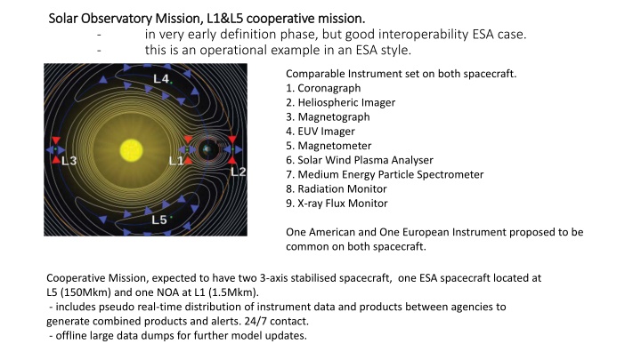
Solar Observatory Mission L1 & L5 Cooperative Mission is in the early definition phase with good interoperability between ESA and NOAA. The mission involves two 3-axis stabilized spacecraft positioned at L5 and L1, each equipped with a similar set of instruments. Real-time data distribution between agencies facilitates the generation of combined products and alerts. The ground segment includes standard ESA operations for continuous real-time data download, distribution, and alert generation, with low latency and offline large data dumps for further analysis and model updates.

Download Presentation

Please find below an Image/Link to download the presentation.
The content on the website is provided AS IS for your information and personal use only. It may not be sold, licensed, or shared on other websites without obtaining consent from the author.If you encounter any issues during the download, it is possible that the publisher has removed the file from their server.
You are allowed to download the files provided on this website for personal or commercial use, subject to the condition that they are used lawfully. All files are the property of their respective owners.
The content on the website is provided AS IS for your information and personal use only. It may not be sold, licensed, or shared on other websites without obtaining consent from the author.
E N D
Presentation Transcript
Solar Observatory Mission, L1&L5 cooperative mission. Solar Observatory Mission, L1&L5 cooperative mission. - in very early definition phase, but good interoperability ESA case. - this is an operational example in an ESA style. Comparable Instrument set on both spacecraft. 1. Coronagraph 2. Heliospheric Imager 3. Magnetograph 4. EUV Imager 5. Magnetometer 6. Solar Wind Plasma Analyser 7. Medium Energy Particle Spectrometer 8. Radiation Monitor 9. X-ray Flux Monitor One American and One European Instrument proposed to be common on both spacecraft. Cooperative Mission, expected to have two 3-axis stabilised spacecraft, one ESA spacecraft located at L5 (150Mkm) and one NOA at L1 (1.5Mkm). - includes pseudo real-time distribution of instrument data and products between agencies to generate combined products and alerts. 24/7 contact. - offline large data dumps for further model updates.
Typical ground segment overview Typical ground segment overview Standard ESA Operations concept for a scientific observatory mission. - continuous realtime data download, distribution and alert generation. - Low latency of data download and distribution. - Realtime cooperation with an equivalent NOAA mission science generation. - offline large science download via optical (supplementary to realtime) - MTL driven schedule. ESOC/MOC Mission Operations Centre ESTRACK SIM S/C Simulator MCS ECC ESTRACK Control Centre Mission Control System WAN SOC Science Operations Centre DDS MPS FDS Data Disposition System Mission Planning System Flight Dynamics System Scientific Mission Planning Instrument Command Requests Science Data Archive & Processing User
ESTRACK European Space Tracking Core elements of the network 35m deep space antennae located in DSA 1: New Norcia (Western Australia) S/X-Band & S/X-Band DSA 2: Cebreros (Spain) X-Band & X/K/Ka-Band DSA 3: Malarg e (Argentina) X/Ka-Band & X/K/Ka-Band Various 12, 13 and 15m class antennas used for S/X-Band LEOP, near Earth and Earth Observation missions, e.g. Kourou (French Guayana) Kiruna (Sweden) One 5.5m antenna used for launcher tracking CEBREROS 35 m ESA UNCLASSIFIED - For Official Use M. Lanucara, K.-J. Schulz, S. Kraft | ESOC | 22/03/2018 | Slide 3
ESTRACK locations ESA UNCLASSIFIED - For Official Use M. Lanucara, K.-J. Schulz, S. Kraft | ESOC | 22/03/2018 | Slide 4
Considerations relevant to L1 / L5 missions Around the clock coverage 24/7 High availability targeted (99% - TBC) Low latency in delivering of the products (15 minutes to 1 hour) Studies identified X-Band as baseline on the basis of Good coverage around the world, and also specifically within ESTRACK Performance reasonably maintained at large availability even at 99% Adequate downlink bandwidth available (10MHz per channel) and no medium term risks of spectrum congestion Ground station would support dual polarisation (currently optional for satellite) Availability of several baselines for Delta DOR tracking, e.g. during the cruise phase to transfer to L5 Sufficient link budget expected for operational purposes Possible North Pacific gap in Estrack 35m coverage. ESA UNCLASSIFIED - For Official Use M. Lanucara, K.-J. Schulz, S. Kraft | ESOC | 22/03/2018 | Slide 5
Typical Operability Standards & IF Documents for ESA Missions. ECSS-E-70-41C, ECSS Space Engineering: Ground Systems and Operations- Telemetry and Telecommand Packet Utilisation, issued 15 April 2016 PLATO Space to Ground Interface Control Document (SGICD) [Part 1] RF and Communications, PTO-ESOC-MOC-ICD-0001, Issue1.0 PLATO Space to Ground Interface Control Document (SGICD) Part 2 TM / TC Data Specification, PTO-ESOC-MOC-ICD-0003, Issue1.0 ESA PSS-04-104, Ranging Standard, ESA, Volume 1, Issue 1, March 1991 ECSS-E-ST-40C, 6 March 2009 Software ECSS-E-ST-50-03C, 31 July 2008 Space data links - Telemetry transfer frame protocol ECSS-E-ST-50-05C Rev. 2, 4 October 2011 Radio Frequency and Modulation Standard ECSS-E-ST-50-04C, 31 July 2008 Space data links-Telecommand protocols, Synchronization and Channel Coding ECSS-E-70C, 31 July 2008 Ground systems and operations ECSS-E-ST-70-11C, 31 July 2008 Space segment operability ECSS-E-ST-70-31C, 31 July 2008 Ground systems and operations- Monitoring and control data definition ECSS-E-ST-70-01C, 16 April 2010 Spacecraft On-Board Control procedures ECSS-E-ST-50C, 31 July 2008 Communications ECSS-E-ST-50-01C, 31 July 2008 Space data links - Telemetry synchronization and channel coding ECSS-E-ST-50-02C, 31 July 2008 Ranging and Doppler tracking ESSB-ST-E-006 Issue 1, 20 July 2011 ESA Procedural Requirements for Frequency Assignment CCSDS 135.0-B-4, October 2009 Space Link Identifiers CCSDS 301.0-B-4, November 2010 Time Code Formats CCSDS 320.0-B-5 Cor. 1, Dec-2013 CCSDS Global Spacecraft Identification Field Code Assignment Control Procedures CCSDS 732.0-B-2, January 2007 File Delivery Protocol (CFDP) CCSDS 720.1-G-3 Apr-2007, CCSDS File Delivery Protocol (CFDP) Part 1: Introduction and Overview, Green book. CCSDS 720.2-G-3 Apr-2007, CCSDS File Delivery Protocol (CFDP) Part 2: Implementers Guide, Green book CCSDS 727.0-B-4 Jan-2007, CCDS File Delivery Protocol, Blue book EGOS-MCS-S2K-ICD-0001 SCOS-2000 Database Import ICD, Version 6.9 GRST-TMTC-ICD-1001 TMTCS SOFTWARE INTERFACE CONTROL DOCUMENT V4.1.4 : VOLUME 2 - EXTERNAL INTERFACES EGOS-GEN-EDDS-ICD-1001 EDDS ICD issue11.0 ESA UNCLASSIFIED - For Official Use M. Lanucara, K.-J. Schulz, S. Kraft | ESOC | 22/03/2018 | Slide 6
Ground Segment Overview (standard layout) High availability space & ground system. 24/7 realtime data download, processing, distribution and alerts. MTL driven, file based offline download L5 orbit is stable, wheel offloading, attitude & antenna pointing without interruption. LEOP Ground Stations X-band Routine Ground Station(s) Nominal Back-up NNO-2 X-band & Optical Demo Maspalomas ESTRACK 35m NASA-DSN Malindi - X S/C / AVM & EGSE TM, TC, Files Tracking TM, TC, Tracking VPN for SVT , SOVT & Launch : TM ,TC, Files, VoIP NDIU Mission Analysis Streaming Data Ingestion Archive System Data Ingestion Archive System Data Dissemination Simulator Network I/F Quick Look Planning Mission Planning Data Analysis Quick Look Mission Control System Data Analysis Flight Dynamics Sys. Data Distribution L/M/S P/L Plan. Data Distribution L/M/S P/L Plan. Ops Support Tools Offline SOC Simulator SOC (TBC) Operational DB MOC (ESOC) SOC (TBC) TC-File, HKTM & OBSW Instrument Teams S/C DB FDS DB SDE/SVF Industry ESAC Responsibility ESOC Responsibility Industry Responsibility Legend: ESA UNCLASSIFIED - For Official Use M. Lanucara, K.-J. Schulz, S. Kraft | ESOC | 22/03/2018 | Slide 7
Standard Mission Data System Infrastructure Reference Architecture ESA Unclassified for Official Use | Spacecraft Operations - Basics | ESA/ESTEC | 2014 | Page 8
Operations Approach (3/6) Verification Verification of system level requirements, flowed down to all ground segment sub-systems Validation Validation of ground segment against test tools, PSS, Simulator, RF- Suitcase All elements of the ground segment are validated in end-to-end System Validation Tests (SVT), SOVTs, MRTs,,, including the space segment, before launch; All operational procedures are validated individually against the space segment or a realistic simulator; Training All members of the Mission Control Team are trained individually in their area of expertise; training by doing is preferred. The Mission Control Team (Flight Control, Flight Dynamics, Ground Control, Spacecraft Manufacturers, Users, Project Team) is trained in a simulations campaign on all nominal and contingency scenarios ESA Unclassified for Official Use | Spacecraft Operations - Basics | ESA/ESTEC | 2013 | Page 9
Operations Approach (4/6) - Validation and Training Set-up Executed following Ground Segment Test and Validation Plan, against operational test tools, with final validation on space segment models. Mission Control Systems Ground Station Interface System Validation Tests Pre-Launch Including all Internal & External Interfaces. Mission Control Systems Ground Station Simulator Simulations (at Control Centre) Spacecraft Simulator Operations Phase Mission Control Systems Flight ESA Unclassified for Official Use | Spacecraft Operations - Basics | ESA/ESTEC | 2013 | Page 10
Operations Approach (5/6) - Validation and Training Schedule SVT-0 S/C location: AIT site When: L- 18 months Duration: ~2days Objective: e2e connectivity, simple commanding test SVT-2 S/C location: Launch site When: L- 4 to 3 months Duration: ~1 week Objective: confidence and regression test Launch LIT Listen In Tests From L-24months When needed on non- interference level Simulations campaign From L-6 to 4 months 2 days per week SOVT & SVT-1 S/C location: AIT site When: L- 12 to 9 months Duration: ~2 weeks Objective: full e2e validation test ESA Unclassified for Official Use | Spacecraft Operations - Basics | ESA/ESTEC | 2013 | Page 11
Operations Approach (6/6) - SVT and Simulations Conduct System Validation Tests Typically conducted from ESOC Dedicated Control Room; AIV team activates spacecraft every morning (but sometimes kept active overnight) and hands over control to ESOC; Systematic test of control functions but also validation of selected operational scenarios; 8 to 10 hours daily testing; parallel tests execution possible; sometimes round the clock tests are required; Plan is revised at the end of each test day. System Operational Validation Tests To and From users / Payload/Science Operations team end to end. Simulations Campaign Mainly conducted from Main Control Room; Briefing, 8 hours simulation, de-briefing; two sims per week; Nominal and several contingency scenarios trained for each critical mission phase. ESA Unclassified for Official Use | Spacecraft Operations - Basics | ESA/ESTEC | 2013 | Page 12
Teams, Roles and Responsibilities Flight Control Team (1/3) SOM POWER SYSTEM SPACON AOCS OBSM Analyst ESA Unclassified for Official Use | Spacecraft Operations - Basics | ESA/ESTEC | 2013 | Page 13


")

")
")
")
")