Overview of CMOS Comparators and Offset Cancellation


EVM and SFO/STO
Date:
2021-04-07
Slide 1
Brian Hart (Cisco Systems)
Apr 2021

Authors:

In D0.4, 11be fixed a long-standing problem with SFO/STO in
the TX EVM test procedure, but more discussion is requested
•
There is an 11me comment on the SFO/STO EVM problem in 11a/HT/VHT, but the PHY experts are
here and 11be has already taken steps to fix its version of the problem
•
These steps were made as part of 20/1958r3, which allowed a STA to use 2 RF LOs to transmit 320
MHz (e.g., 160+160 MHz segments), but ultimately
this EVM topic is orthogonal to 2 RF LOs
.
•
20/1958r3 added “single” to the TX EVM procedure to make it clear that receivers did not need to
perform CFO estimation/correction or pilot estimation per 160 MHz but, at the same time, there was a
concern that this “single” would incorrectly harden the language against correction of both CPE and
STO, so in D0.4 it was clarified that a
single
estimate of
both
CPE and STO was performed:
•
However, some questions have been raised on these 11be steps, and some wider discussion was
requested. E.g., STO can be corrected from CPE without a further estimation.
Slide 2
Brian Hart (Cisco Systems)
Apr 2021
STO Concerns: the 802.11a/n/ac/ax TX EVM
Procedures Miss the Mark on Two Goals
•
Goal A: Incorrect calculations by the
receiving
test equipment should
not contribute to the numerator (error) quantity in the EVM calculation
and thereby penalize the
transmitter
•
Goal B: If two entities (e.g., vendor and customer) independently
follow the 802.11 EVM test procedures to test a STAUT, they should
both agree if the STAUT passed or failed
•
Sadly the 802.11beD0.3 TX EVM procedure missed the mark on both
these items (the same as for 11a/HT/VHT/HE over 22 years)
•
Out of necessity, unwritten conventions were adopted
, and test
equipment vendors provide customers with further workarounds [1]
Slide 3
Brian Hart (Cisco Systems)
Apr 2021
Impact of Oscillator Offsets (1/2)
•
In 5/6 GHz, STAUTs are allowed to have +-20ppm offset in their
reference oscillator
•
This manifests itself as
Carrier Frequency Offset (CFO; aka
“frequency offset”) within the mixer and
Sampling Frequency
Offset (SFO; aka “sampling offset drift”) within the ADCs
•
The EVM test procedures have always dealt with CFO thoroughly
and explicitly:
•
Frequency offset is estimated and corrected during the preamble
•
Because of various impairments, the test equipment can never estimate CFO perfectly, but
the majority of the CFO is removed here
•
The effect of any residual CFO (i.e., actual CFO minus estimated CFO) appears as
Common Phase Error (CPE) that increases every OFDM symbol.
•
The EVM procedure allows this CFO residue (and other impairments such as
carrier phase noise) to be estimated and corrected using the pilot tones during the
EHT-LTF and Data fields
Slide 4
Brian Hart (Cisco Systems)
Apr 2021
Impact of Oscillator Offsets (2/2)
•
The EVM test procedures have never dealt with SFO adequately:
•
In 11a/HT/VHT, there is no text at all (see backup)
•
In HE/EHT, step d) says “Sampling offset drift [
=SFO
] shall be also compensated”
•
There is no text describing how sampling offset drift should be determined, so presumably
it is
calculated
(not independently
estimated
) from the estimated CFO, since the estimated
CFO and known carrier frequency allow the underlying reference oscillator offset (ppm)
to be determined
•
Because of the position of the text, the strong implication is that the SFO calculation is
made one time during the preamble, and the subsequent correction (e.g., digital
resampling with a fixed ratio) continues unchanged for the duration of the PPDU
•
SFO correction is a natural requirement given the dense subcarriers of HE/EHT, since
otherwise ICI dominates the calculated EVM
•
Because of various impairments, the test equipment can never estimate the (CFO or)
reference oscillator offset perfectly, yet still the majority of the HE/EHT SFO is removed
here
•
The effect of any residual SFO (i.e., actual SFO minus estimated SFO) appears as
Symbol Timing Offset (STO) that increases every OFDM symbol.
Slide 5
Brian Hart (Cisco Systems)
Apr 2021
•
STO due to residual SFO increases over time, but
•
The simplest interpretation of the EVM test procedure is that residual STO is
neither estimated nor corrected per OFDM symbol:
•
g) For each of the data OFDM symbols, transform the symbol into subcarrier received
values, estimate the phase [
CPE
] from the pilot subcarriers, and compensate the subcarrier
values according to the estimated phase [
i.e. CPE-compensation only
], group the results
from all of the receiver chains in each subcarrier to a vector, and multiply the vector by a
zero-forcing equalization matrix generated from the estimated channel
•
The PPDUs under test shall be
at least
16 (or 32) data OFDM symbols long
•
The EVM calculation uses
all
transmitted OFDM symbols
•
.
STO Was Not Adequately Addressed by
the D0.3 802.11 EVM Test Procedure
Slide 6
Brian Hart (Cisco Systems)
Apr 2021
How Goal A and B Are Not Met
•
Goal A is not met because STO due to the test equipment making
an imperfect estimate of the SFO is not the fault of the
transmitter
.
•
Tolerable only if the EVM contribution due to mis-estimated SFO isn’t “the straw
that breaks the camel’s back” and causes the measured EVM to flip from passing to
failing (being well below the EVM limit is
usually
sufficient)
•
Goal B is not met because EVM is calculated over
at least
16 (or
32) OFDM symbols:
•
Vendor might test over
16 (or 32)
OFDM symbols and report that their product
passes
•
Customer might test over
max
OFDM symbols (as they’re entitled to do) and –
with bad enough residual STO – report that the vendor’s product fails
•
… This doesn’t happen in practice because of
unwritten
rules such as
don’t
test
EVM over max OFDM symbols
•
Unwritten rules mean that the underlying standard is incomplete
Slide 7
Brian Hart (Cisco Systems)
Apr 2021
Simulated Impact of Residual SFO for EHT
•
Plot shows 802.11 EVM versus number of
OFDM symbols in the Data field for various
TX ppm’s
•
EVM limit for MCS12/13 is -38 dB
•
At 16 OFDM symbols, need <0.05ppm
residual SFO for its contribution to be
negligible (realistic, given HETB also needs
to maintain 350 Hz / 7 GHz = 0.05ppm of
accuracy)
•
But care is still needed: 0.2ppm residual SFO
would cause STAUT to fail test
•
With 399 OFDM symbols, need <0.002ppm
residual SFO for its contribution to be
negligible, which is surely unrealistic
Slide 8
Brian Hart (Cisco Systems)
Apr 2021
•
320MHz, 4KQAM, 1SS, 0.8us GI, 4x EHTLTF, 20
random Data fields, 100ns windowing
•
No impairments except SFO, ideal CPE correction
(0 always) and equalization
Mitigation Options
•
Option 0: No change to D0.4
•
Explicit reference to CPE and STO estimation and compensation during EHTLTFs and Data field
•
Option 1: Revert EVM text changes in 20/1958r3, then change “estimate the phase” to “estimate a single
phase” for the EHTLTF and Data fields
•
i.e., limit 20/1958r3 to fixing 2 RF LOs, and leave EVM with the two Goals unmet and unaddressed; continue the discussion in 11me
•
Option 1a: Like Option 1 during the Data field, but allow CPE and STO correction during the EHTLTFs
but
not
during the Data field
•
i.e., limit 20/1958r3 to fixing 2 RF LOs, and leave EVM with the two Goals unmet and unaddressed; continue the discussion in 11me
•
Option 2: Limit the EVM calculation to the first 16 (or 32 for ru26) OFDM symbols in the Data field
•
Though, then EVM degradations after 16/32 symbols in longer PPDUs are untested
•
(Option 3a: Allow STO correction whenever residual SFO would cause an EVM degradation above EVM
threshold – 10 dB
•
But how is residual SFO itself estimated? – and if from the pilots, then this is really option 0 again)
•
Option 3b: Allow STO correction after every 16 (or 32 for ru26) OFDM symbols in the Data field
•
Option 3c: Allow STO correction after every 32 OFDM symbols in the Data field
•
Options 3b and 3c are NOT intended to model actual receiver implementations; only that implementations do address STO (in whatever way)
•
Options 3b and 3c have the advantage than a) cumulative STO is corrected before it affects EVM, b) the EVM test is well defined however long the
PPDU is, c) existing EVM measurements over 16/32 OFDM symbols are still valid, d) this still encourages “clean” transmitters since any STO-related
impairments not related to oscillator offset between the 16/32 OFDM symbols need to be kept small
Slide 9
Brian Hart (Cisco Systems)
Apr 2021
Strawpoll
•
If we were to change the text from D0.4, vote Y/N/A on each of the
following:
•
Option 1: Revert EVM text changes in 20/1958r3, then change “estimate the phase” to
“estimate a single phase” for the EHTLTF and Data fields
•
Option 1a: Continue to allow CPE and STO correction during the EHTLTFs but
not
during the
Data field (see backup for sample language)
•
Option 2: Limit the EVM calculation to the first 16 (or 32 for ru26) OFDM symbols in the Data
field
•
Option 3b: Allow STO correction after every 16 (or 32 for ru26) OFDM symbols in the Data
field
•
Option 3c: Allow STO correction after every 32 OFDM symbols in the Data field
Slide 10
Brian Hart (Cisco Systems)
Apr 2021
References
[1]
https://www.rohde-schwarz.com/us/manual/r-s-fsw-k91-wlan-user-manual-manuals-
gb1_78701-28989.html
(and thence
https://scdn.rohde-
schwarz.com/ur/pws/dl_downloads/pdm/cl_manuals/user_manual/1173_9357_01/FSW_K91_WLA
N_UserManual_en_34.pdf
; see pages 72 and 204)
Slide 11
Brian Hart (Cisco Systems)
Apr 2021
Backup
Slide 12
Brian Hart (Cisco Systems)
Apr 2021
Sample language for Option 1
Slide 13
Brian Hart (Cisco Systems)
Apr 2021
…
c) Coarse and fine frequency offsets shall be estimated.
d) Symbols in a PPDU shall be derotated according to a single estimated frequency offset. Sampling offset drift shall be also
compensated.
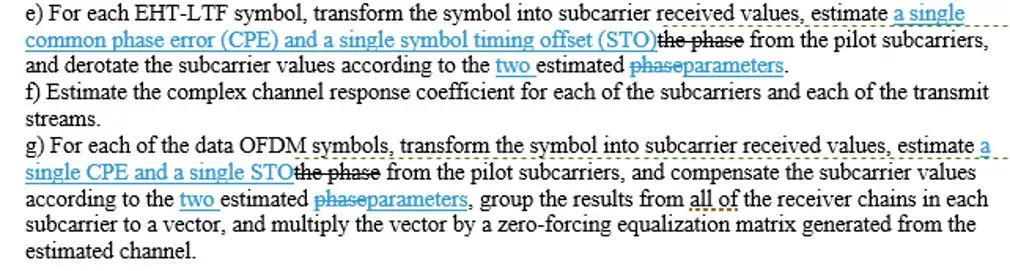
e) For each EHT-LTF symbol, transform the symbol into subcarrier received values, estimate
a single phase
a single common phase
error (CPE) and a single symbol timing offset (STO)
from the pilot subcarriers, and derotate the subcarrier values according to
the
estimated phase
two estimated parameters
.
f) Estimate the complex channel response coefficient for each of the subcarriers and each of the transmit streams.
g) For each of the data OFDM symbols, transform the symbol into subcarrier received values, estimate
a single phase
a single CPE and
a single STO
from the pilot subcarriers, and compensate the subcarrier values according to the
estimated phase
two estimated
parameters
, group the results from all of the receiver chains in each subcarrier to a vector, and multiply the vector by a zero-
forcing equalization matrix generated from the estimated channel.
…
N
SYM
is the number of data OFDM symbols.
Sample language for Option 1a
Slide 14
Brian Hart (Cisco Systems)
Apr 2021
…
c) Coarse and fine frequency offsets shall be estimated.
d) Symbols in a PPDU shall be derotated according to a single estimated frequency offset. Sampling offset drift shall be also
compensated.
e) For each EHT-LTF symbol, transform the symbol into subcarrier received values, estimate
a single phase
a single common phase
error (CPE) and a single symbol timing offset (STO)
from the pilot subcarriers, and derotate the subcarrier values according to
the
estimated phase
two estimated parameters
.
Symbol timing offset (STO) shall be also compensated according to a single
parameter per EHT-LTF symbol
.
f) Estimate the complex channel response coefficient for each of the subcarriers and each of the transmit streams.
g) For each of the data OFDM symbols, transform the symbol into subcarrier received values, estimate
a single CPE
and a single STO
from the pilot subcarriers, and compensate the subcarrier values according to the
estimated CPE
two estimated parameters
, group
the results from all of the receiver chains in each subcarrier to a vector, and multiply the vector by a zero-forcing equalization
matrix generated from the estimated channel.
…
N
SYM
is the number of data OFDM symbols.
Sample language for Option 2
Slide 15
Brian Hart (Cisco Systems)
Apr 2021
…
c) Coarse and fine frequency offsets shall be estimated.
d) Symbols in a PPDU shall be derotated according to a single estimated frequency offset. Sampling offset drift shall be also
compensated.
e) For each EHT-LTF symbol, transform the symbol into subcarrier received values, estimate
a single phase
a single common phase
error (CPE) and a single symbol timing offset (STO)
from the pilot subcarriers, and derotate the subcarrier values according to
the
estimated phase
two estimated parameters
.
f) Estimate the complex channel response coefficient for each of the subcarriers and each of the transmit streams.
g) For each of the data OFDM symbols, transform the symbol into subcarrier received values, estimate
a single phase
a single CPE and
a single STO
from the pilot subcarriers, and compensate the subcarrier values according to the
estimated phase
two estimated
parameters
, group the results from all of the receiver chains in each subcarrier to a vector, and multiply the vector by a zero-
forcing equalization matrix generated from the estimated channel.
…
N
SYM,EVM
equals 32 data OFDM symbols for occupied RUs with 26 tones and 16 data OFDM symbols for occupied RUs with more than
26 tones.
N
SYM
is the number of data OFDM symbols.
Change
N
SYM
to
N
SYM,EVM
Sample language for Option 3b/c
Slide 16
Brian Hart (Cisco Systems)
Apr 2021
…
c) Coarse and fine frequency offsets shall be estimated.
d) Symbols in a PPDU shall be derotated according to a single estimated frequency offset. Sampling offset drift shall be also
compensated.
e) For each EHT-LTF symbol, transform the symbol into subcarrier received values, estimate a single common phase error (CPE) and a
single symbol timing offset (STO) from the pilot subcarriers, and derotate the subcarrier values according to the two estimated
parameters.
f) Estimate the complex channel response coefficient for each of the subcarriers and each of the transmit streams.
g) For each of the data OFDM symbols, transform the symbol into subcarrier received values,
and
estimate a single CPE
and a single
STO
from the pilot subcarriers
. After every
N
SYM,STO
OFDM symbols, calculate a single STO for the next
N
SYM,STO
OFDM
symbols.
, and c
Compensate the subcarrier values according to the
estimated CPE and STO
two estimated parameters
, group the
results from all of the receiver chains in each subcarrier to a vector, and multiply the vector by a zero-forcing equalization matrix
generated from the estimated channel.
Option 3b:
N
SYM,STO
equals 32 for occupied RUs with 26 tones and 16 for occupied RUs with more than 26 tones.
Option 3c:
N
SYM,STO
equals 32 for all occupied RUs.
N
SYM
is the number of data OFDM symbols.
The Situation is Worse for 11a/HT/VHT
Slide 17
Brian Hart (Cisco Systems)
Apr 2021
•
Nothing like “Sampling offset drift shall be also compensated.” in step d), so at 5 GHz the residual SFO is
+-20ppm
“b) Transition from L-STF to L-LTF shall be detected and fine timing shall be established.
c) Coarse and fine frequency offsets shall be estimated.
d) Symbols in a PPDU shall be derotated according to estimated frequency offset.”
•
Again, the plain reading of the EVM test procedure is that residual STO is neither estimated nor corrected per OFDM
symbol:
g) For each of the data OFDM symbols, transform the symbol into subcarrier received values, estimate
the
phase [
CPE
] from the pilot
subcarriers, derotate the subcarrier values according to
the estimated phase
[
i.e. CPE-compensation only
], group the results from all of the
receiver chains in each subcarrier to a vector, and multiply the vector by a zero-forcing equalization matrix generated from the estimated
channel …
•
The PPDUs under test shall be
at least
16 data OFDM symbols long
•
The EVM calculation refers to Nsym, which is defined elsewhere as the
total
number of OFDM symbols in the Data field
Simulated Impact of Residual SFO for 11a
•
Plot shows 802.11 EVM versus number of
OFDM symbols in the Data field for various
TX ppm’s
•
EVM limit for 54 Mbps is -25 dB
•
At 16 OFDM symbols, EVM contribution
from 20ppm SFO is negligible
•
This may be the reason why SFO/STO was not
mentioned in the 802.11a EVM procedure
•
For maximum length PPDUs, need 0.2ppm
SFO for its contribution to be negligible
•
Yet 11a devices are allowed to have up to +-
20ppm oscillator offsets
•
So there was still a flaw
Slide 18
Brian Hart (Cisco Systems)
Apr 2021
•
20MHz, 64QAM, 1SS, 0.8us GI, 20 random Data
fields, 100ns windowing
•
No impairments except SFO, ideal CPE correction
(0 always) and equalization
Simulated Impact of Residual SFO for HT
•
Plot shows 802.11 EVM versus number of
OFDM symbols in the Data field for various
TX ppm’s
•
EVM limit for HT MCS7 is -27 dB
•
At 16 OFDM symbols, need 5-10ppm SFO
for its contribution to be negligible
•
For maximum length PPDUs, need 0.05ppm
SFO for its contribution to be negligible
•
Yet HT devices are allowed to have up to +-
20ppm oscillator offsets at 5 GHz
•
The flaw continues
Slide 19
Brian Hart (Cisco Systems)
Apr 2021
•
40MHz, 64QAM, 1SS, 0.4us GI, 20 random Data
fields, 100ns windowing
•
No impairments except SFO, ideal CPE correction
(0 always) and equalization
Simulated Impact of Residual SFO for VHT
•
Plot shows 802.11 EVM versus number of
OFDM symbols in the Data field for various
TX ppm’s
•
EVM limit for VHT MCS9 is -32 dB
•
At 16 OFDM symbols, need 1ppm SFO for
its contribution to be negligible
•
Different from EHT since EHT has 2x BW, OFDM
symbols are 13.6/3.6 = 3.8x longer, EVM
requirements for 4KQAM are higher than for
256QAM
•
For maximum length PPDUs, need 0.01-
0.02ppm SFO for its contribution to be
negligible
•
Yet VHT devices are allowed to have up to
+-20ppm oscillator offsets
•
The flaw continues
Slide 20
Brian Hart (Cisco Systems)
Apr 2021
•
160MHz, 256QAM, 1SS, 0.4us GI, 20 random Data
fields, 100ns windowing
•
No impairments except SFO, ideal CPE correction
(0 always) and equalization
doc.: IEEE 802.11-yy/xxxxr0
Month Year
John Doe, Some Company
Page
world of CMOS comparators and learn about offset cancellation techniques. Dive into practical offset cancellation methods and the use of opamps as comparators. Discover the benefits of fully-differential comparators and dynamic comparators with regenerative gain. Uncover small-signal models and the need for RS latch in dynamic comparator applications.

Download Presentation

Please find below an Image/Link to download the presentation.
The content on the website is provided AS IS for your information and personal use only. It may not be sold, licensed, or shared on other websites without obtaining consent from the author.If you encounter any issues during the download, it is possible that the publisher has removed the file from their server.
You are allowed to download the files provided on this website for personal or commercial use, subject to the condition that they are used lawfully. All files are the property of their respective owners.
The content on the website is provided AS IS for your information and personal use only. It may not be sold, licensed, or shared on other websites without obtaining consent from the author.
E N D
Presentation Transcript
Apr 2021 doc.: IEEE 802.11-21/0618r0 EVM and SFO/STO Date: 2021-04-07 Authors: Name Brian Hart Affiliations Address Cisco Systems Phone email brianh@cisco.com Submission Slide 1 Brian Hart (Cisco Systems)
Apr 2021 doc.: IEEE 802.11-21/0618r0 In D0.4, 11be fixed a long-standing problem with SFO/STO in the TX EVM test procedure, but more discussion is requested There is an 11me comment on the SFO/STO EVM problem in 11a/HT/VHT, but the PHY experts are here and 11be has already taken steps to fix its version of the problem These steps were made as part of 20/1958r3, which allowed a STA to use 2 RF LOs to transmit 320 MHz (e.g., 160+160 MHz segments), but ultimately this EVM topic is orthogonal to 2 RF LOs. 20/1958r3 added single to the TX EVM procedure to make it clear that receivers did not need to perform CFO estimation/correction or pilot estimation per 160 MHz but, at the same time, there was a concern that this single would incorrectly harden the language against correction of both CPE and STO, so in D0.4 it was clarified that a single estimate of both CPE and STO was performed: However, some questions have been raised on these 11be steps, and some wider discussion was requested. E.g., STO can be corrected from CPE without a further estimation. Slide 2 Submission Brian Hart (Cisco Systems)
Apr 2021 doc.: IEEE 802.11-21/0618r0 STO Concerns: the 802.11a/n/ac/ax TX EVM Procedures Miss the Mark on Two Goals Goal A: Incorrect calculations by the receiving test equipment should not contribute to the numerator (error) quantity in the EVM calculation and thereby penalize the transmitter Goal B: If two entities (e.g., vendor and customer) independently follow the 802.11 EVM test procedures to test a STAUT, they should both agree if the STAUT passed or failed Sadly the 802.11beD0.3 TX EVM procedure missed the mark on both these items (the same as for 11a/HT/VHT/HE over 22 years) Out of necessity, unwritten conventions were adopted, and test equipment vendors provide customers with further workarounds [1] Submission Slide 3 Brian Hart (Cisco Systems)
Apr 2021 doc.: IEEE 802.11-21/0618r0 Impact of Oscillator Offsets (1/2) In 5/6 GHz, STAUTs are allowed to have +-20ppm offset in their reference oscillator This manifests itself as Carrier Frequency Offset (CFO; aka frequency offset ) within the mixer and Sampling Frequency Offset (SFO; aka sampling offset drift ) within the ADCs The EVM test procedures have always dealt with CFO thoroughly and explicitly: Frequency offset is estimated and corrected during the preamble Because of various impairments, the test equipment can never estimate CFO perfectly, but the majority of the CFO is removed here The effect of any residual CFO (i.e., actual CFO minus estimated CFO) appears as Common Phase Error (CPE) that increases every OFDM symbol. The EVM procedure allows this CFO residue (and other impairments such as carrier phase noise) to be estimated and corrected using the pilot tones during the EHT-LTF and Data fields Slide 4 Submission Brian Hart (Cisco Systems)
Apr 2021 doc.: IEEE 802.11-21/0618r0 Impact of Oscillator Offsets (2/2) The EVM test procedures have never dealt with SFO adequately: In 11a/HT/VHT, there is no text at all (see backup) In HE/EHT, step d) says Sampling offset drift [=SFO] shall be also compensated There is no text describing how sampling offset drift should be determined, so presumably it is calculated (not independently estimated) from the estimated CFO, since the estimated CFO and known carrier frequency allow the underlying reference oscillator offset (ppm) to be determined Because of the position of the text, the strong implication is that the SFO calculation is made one time during the preamble, and the subsequent correction (e.g., digital resampling with a fixed ratio) continues unchanged for the duration of the PPDU SFO correction is a natural requirement given the dense subcarriers of HE/EHT, since otherwise ICI dominates the calculated EVM Because of various impairments, the test equipment can never estimate the (CFO or) reference oscillator offset perfectly, yet still the majority of the HE/EHT SFO is removed here The effect of any residual SFO (i.e., actual SFO minus estimated SFO) appears as Symbol Timing Offset (STO) that increases every OFDM symbol. Submission Slide 5 Brian Hart (Cisco Systems)
Apr 2021 doc.: IEEE 802.11-21/0618r0 STO Was Not Adequately Addressed by the D0.3 802.11 EVM Test Procedure STO due to residual SFO increases over time, but The simplest interpretation of the EVM test procedure is that residual STO is neither estimated nor corrected per OFDM symbol: g) For each of the data OFDM symbols, transform the symbol into subcarrier received values, estimate the phase [CPE] from the pilot subcarriers, and compensate the subcarrier values according to the estimated phase [i.e. CPE-compensation only], group the results from all of the receiver chains in each subcarrier to a vector, and multiply the vector by a zero-forcing equalization matrix generated from the estimated channel The PPDUs under test shall be at least 16 (or 32) data OFDM symbols long The EVM calculation uses all transmitted OFDM symbols Submission Slide 6 Brian Hart (Cisco Systems) .
Apr 2021 doc.: IEEE 802.11-21/0618r0 How Goal A and B Are Not Met Goal A is not met because STO due to the test equipment making an imperfect estimate of the SFO is not the fault of the transmitter. Tolerable only if the EVM contribution due to mis-estimated SFO isn t the straw that breaks the camel s back and causes the measured EVM to flip from passing to failing (being well below the EVM limit is usually sufficient) Goal B is not met because EVM is calculated over at least 16 (or 32) OFDM symbols: Vendor might test over 16 (or 32) OFDM symbols and report that their product passes Customer might test over max OFDM symbols (as they re entitled to do) and with bad enough residual STO report that the vendor s product fails This doesn t happen in practice because of unwritten rules such as don t test EVM over max OFDM symbols Unwritten rules mean that the underlying standard is incomplete Submission Slide 7 Brian Hart (Cisco Systems)
Apr 2021 doc.: IEEE 802.11-21/0618r0 Simulated Impact of Residual SFO for EHT Plot shows 802.11 EVM versus number of OFDM symbols in the Data field for various TX ppm s EVM limit for MCS12/13 is -38 dB At 16 OFDM symbols, need <0.05ppm residual SFO for its contribution to be negligible (realistic, given HETB also needs to maintain 350 Hz / 7 GHz = 0.05ppm of accuracy) But care is still needed: 0.2ppm residual SFO would cause STAUT to fail test With 399 OFDM symbols, need <0.002ppm residual SFO for its contribution to be negligible, which is surely unrealistic 320MHz, 4KQAM, 1SS, 0.8us GI, 4x EHTLTF, 20 random Data fields, 100ns windowing No impairments except SFO, ideal CPE correction (0 always) and equalization Submission Slide 8 Brian Hart (Cisco Systems)
Apr 2021 doc.: IEEE 802.11-21/0618r0 Mitigation Options Option 0: No change to D0.4 Explicit reference to CPE and STO estimation and compensation during EHTLTFs and Data field Option 1: Revert EVM text changes in 20/1958r3, then change estimate the phase to estimate a single phase for the EHTLTF and Data fields i.e., limit 20/1958r3 to fixing 2 RF LOs, and leave EVM with the two Goals unmet and unaddressed; continue the discussion in 11me Option 1a: Like Option 1 during the Data field, but allow CPE and STO correction during the EHTLTFs but not during the Data field i.e., limit 20/1958r3 to fixing 2 RF LOs, and leave EVM with the two Goals unmet and unaddressed; continue the discussion in 11me Option 2: Limit the EVM calculation to the first 16 (or 32 for ru26) OFDM symbols in the Data field Though, then EVM degradations after 16/32 symbols in longer PPDUs are untested (Option 3a: Allow STO correction whenever residual SFO would cause an EVM degradation above EVM threshold 10 dB But how is residual SFO itself estimated? and if from the pilots, then this is really option 0 again) Option 3b: Allow STO correction after every 16 (or 32 for ru26) OFDM symbols in the Data field Option 3c: Allow STO correction after every 32 OFDM symbols in the Data field Options 3b and 3c are NOT intended to model actual receiver implementations; only that implementations do address STO (in whatever way) Options 3b and 3c have the advantage than a) cumulative STO is corrected before it affects EVM, b) the EVM test is well defined however long the PPDU is, c) existing EVM measurements over 16/32 OFDM symbols are still valid, d) this still encourages clean transmitters since any STO-related impairments not related to oscillator offset between the 16/32 OFDM symbols need to be kept small Submission Slide 9 Brian Hart (Cisco Systems)
Apr 2021 doc.: IEEE 802.11-21/0618r0 Strawpoll If we were to change the text from D0.4, vote Y/N/A on each of the following: Option 1: Revert EVM text changes in 20/1958r3, then change estimate the phase to estimate a single phase for the EHTLTF and Data fields Option 1a: Continue to allow CPE and STO correction during the EHTLTFs but not during the Data field (see backup for sample language) Option 2: Limit the EVM calculation to the first 16 (or 32 for ru26) OFDM symbols in the Data field Option 3b: Allow STO correction after every 16 (or 32 for ru26) OFDM symbols in the Data field Option 3c: Allow STO correction after every 32 OFDM symbols in the Data field Submission Slide 10 Brian Hart (Cisco Systems)
Apr 2021 doc.: IEEE 802.11-21/0618r0 References [1] https://www.rohde-schwarz.com/us/manual/r-s-fsw-k91-wlan-user-manual-manuals- gb1_78701-28989.html (and thence https://scdn.rohde- schwarz.com/ur/pws/dl_downloads/pdm/cl_manuals/user_manual/1173_9357_01/FSW_K91_WLA N_UserManual_en_34.pdf ; see pages 72 and 204) Submission Slide 11 Brian Hart (Cisco Systems)
Apr 2021 doc.: IEEE 802.11-21/0618r0 Backup Submission Slide 12 Brian Hart (Cisco Systems)
Apr 2021 doc.: IEEE 802.11-21/0618r0 Sample language for Option 1 c) Coarse and fine frequency offsets shall be estimated. d) Symbols in a PPDU shall be derotated according to a single estimated frequency offset. Sampling offset drift shall be also compensated. e) For each EHT-LTF symbol, transform the symbol into subcarrier received values, estimate a single phasea single common phase error (CPE) and a single symbol timing offset (STO) from the pilot subcarriers, and derotate the subcarrier values according to the estimated phasetwo estimated parameters. f) Estimate the complex channel response coefficient for each of the subcarriers and each of the transmit streams. g) For each of the data OFDM symbols, transform the symbol into subcarrier received values, estimate a single phasea single CPE and a single STO from the pilot subcarriers, and compensate the subcarrier values according to the estimated phasetwo estimated parameters, group the results from all of the receiver chains in each subcarrier to a vector, and multiply the vector by a zero- forcing equalization matrix generated from the estimated channel. NSYM is the number of data OFDM symbols. Submission Slide 13 Brian Hart (Cisco Systems)
Apr 2021 doc.: IEEE 802.11-21/0618r0 Sample language for Option 1a c) Coarse and fine frequency offsets shall be estimated. d) Symbols in a PPDU shall be derotated according to a single estimated frequency offset. Sampling offset drift shall be also compensated. e) For each EHT-LTF symbol, transform the symbol into subcarrier received values, estimate a single phasea single common phase error (CPE) and a single symbol timing offset (STO) from the pilot subcarriers, and derotate the subcarrier values according to the estimated phasetwo estimated parameters. Symbol timing offset (STO) shall be also compensated according to a single parameter per EHT-LTF symbol. f) Estimate the complex channel response coefficient for each of the subcarriers and each of the transmit streams. g) For each of the data OFDM symbols, transform the symbol into subcarrier received values, estimate a single CPE and a single STO from the pilot subcarriers, and compensate the subcarrier values according to the estimated CPEtwo estimated parameters, group the results from all of the receiver chains in each subcarrier to a vector, and multiply the vector by a zero-forcing equalization matrix generated from the estimated channel. NSYM is the number of data OFDM symbols. Submission Slide 14 Brian Hart (Cisco Systems)
Apr 2021 doc.: IEEE 802.11-21/0618r0 Sample language for Option 2 c) Coarse and fine frequency offsets shall be estimated. d) Symbols in a PPDU shall be derotated according to a single estimated frequency offset. Sampling offset drift shall be also compensated. e) For each EHT-LTF symbol, transform the symbol into subcarrier received values, estimate a single phasea single common phase error (CPE) and a single symbol timing offset (STO) from the pilot subcarriers, and derotate the subcarrier values according to the estimated phasetwo estimated parameters. f) Estimate the complex channel response coefficient for each of the subcarriers and each of the transmit streams. g) For each of the data OFDM symbols, transform the symbol into subcarrier received values, estimate a single phasea single CPE and a single STO from the pilot subcarriers, and compensate the subcarrier values according to the estimated phasetwo estimated parameters, group the results from all of the receiver chains in each subcarrier to a vector, and multiply the vector by a zero- forcing equalization matrix generated from the estimated channel. Change NSYM to NSYM,EVM NSYM,EVMequals 32 data OFDM symbols for occupied RUs with 26 tones and 16 data OFDM symbols for occupied RUs with more than 26 tones.NSYM is the number of data OFDM symbols. Submission Slide 15 Brian Hart (Cisco Systems)
Apr 2021 doc.: IEEE 802.11-21/0618r0 Sample language for Option 3b/c c) Coarse and fine frequency offsets shall be estimated. d) Symbols in a PPDU shall be derotated according to a single estimated frequency offset. Sampling offset drift shall be also compensated. e) For each EHT-LTF symbol, transform the symbol into subcarrier received values, estimate a single common phase error (CPE) and a single symbol timing offset (STO) from the pilot subcarriers, and derotate the subcarrier values according to the two estimated parameters. f) Estimate the complex channel response coefficient for each of the subcarriers and each of the transmit streams. g) For each of the data OFDM symbols, transform the symbol into subcarrier received values, and estimate a single CPE and a single STO from the pilot subcarriers. After every NSYM,STOOFDM symbols, calculate a single STO for the next NSYM,STOOFDM symbols. , and cCompensate the subcarrier values according to the estimated CPE and STOtwo estimated parameters, group the results from all of the receiver chains in each subcarrier to a vector, and multiply the vector by a zero-forcing equalization matrix generated from the estimated channel. Option 3b: NSYM,STO equals 32 for occupied RUs with 26 tones and 16 for occupied RUs with more than 26 tones. Option 3c: NSYM,STOequals 32 for all occupied RUs. NSYM is the number of data OFDM symbols. Submission Slide 16 Brian Hart (Cisco Systems)
Apr 2021 doc.: IEEE 802.11-21/0618r0 The Situation is Worse for 11a/HT/VHT Nothing like Sampling offset drift shall be also compensated. in step d), so at 5 GHz the residual SFO is +-20ppm b) Transition from L-STF to L-LTF shall be detected and fine timing shall be established. c) Coarse and fine frequency offsets shall be estimated. d) Symbols in a PPDU shall be derotated according to estimated frequency offset. Again, the plain reading of the EVM test procedure is that residual STO is neither estimated nor corrected per OFDM symbol: g) For each of the data OFDM symbols, transform the symbol into subcarrier received values, estimate the phase [CPE] from the pilot subcarriers, derotate the subcarrier values according to the estimated phase [i.e. CPE-compensation only], group the results from all of the receiver chains in each subcarrier to a vector, and multiply the vector by a zero-forcing equalization matrix generated from the estimated channel The PPDUs under test shall be at least 16 data OFDM symbols long The EVM calculation refers to Nsym, which is defined elsewhere as the total number of OFDM symbols in the Data field Submission Slide 17 Brian Hart (Cisco Systems)
Apr 2021 doc.: IEEE 802.11-21/0618r0 Simulated Impact of Residual SFO for 11a Plot shows 802.11 EVM versus number of OFDM symbols in the Data field for various TX ppm s EVM limit for 54 Mbps is -25 dB At 16 OFDM symbols, EVM contribution from 20ppm SFO is negligible This may be the reason why SFO/STO was not mentioned in the 802.11a EVM procedure For maximum length PPDUs, need 0.2ppm SFO for its contribution to be negligible Yet 11a devices are allowed to have up to +- 20ppm oscillator offsets So there was still a flaw 20MHz, 64QAM, 1SS, 0.8us GI, 20 random Data fields, 100ns windowing No impairments except SFO, ideal CPE correction (0 always) and equalization Submission Slide 18 Brian Hart (Cisco Systems)
Apr 2021 doc.: IEEE 802.11-21/0618r0 Simulated Impact of Residual SFO for HT Plot shows 802.11 EVM versus number of OFDM symbols in the Data field for various TX ppm s EVM limit for HT MCS7 is -27 dB At 16 OFDM symbols, need 5-10ppm SFO for its contribution to be negligible For maximum length PPDUs, need 0.05ppm SFO for its contribution to be negligible Yet HT devices are allowed to have up to +- 20ppm oscillator offsets at 5 GHz The flaw continues 40MHz, 64QAM, 1SS, 0.4us GI, 20 random Data fields, 100ns windowing No impairments except SFO, ideal CPE correction (0 always) and equalization Submission Slide 19 Brian Hart (Cisco Systems)
Apr 2021 doc.: IEEE 802.11-21/0618r0 Simulated Impact of Residual SFO for VHT Plot shows 802.11 EVM versus number of OFDM symbols in the Data field for various TX ppm s EVM limit for VHT MCS9 is -32 dB At 16 OFDM symbols, need 1ppm SFO for its contribution to be negligible Different from EHT since EHT has 2x BW, OFDM symbols are 13.6/3.6 = 3.8x longer, EVM requirements for 4KQAM are higher than for 256QAM For maximum length PPDUs, need 0.01- 0.02ppm SFO for its contribution to be negligible Yet VHT devices are allowed to have up to +-20ppm oscillator offsets The flaw continues 160MHz, 256QAM, 1SS, 0.4us GI, 20 random Data fields, 100ns windowing No impairments except SFO, ideal CPE correction (0 always) and equalization Submission Slide 20 Brian Hart (Cisco Systems)