NMOS Transistors in CMOS Logic Circuits

MOS Transistors
CMOS Inverter
and Logic Families

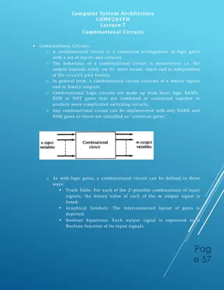
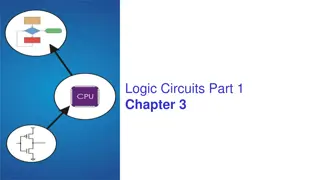
Levels-of-Design Pyramid
2
Transistors

Gates

MSI Circuits
(Adders, Multiplexers)
Systems
n
-
t
y
p
e
o
x
i
d
e
i
n
s
u
l
a
t
o
r
m
e
t
a
l
p
-
t
y
p
e
m
e
t
a
l
g
a
t
e
s
o
u
r
c
e
d
r
a
i
n
n
-
t
y
p
e
e
e
e
e
e
e
h
h
h
h
h
h
NMOS (N-Channel Metal Oxide Semiconductor)
transistor
3
h
“Doping” silicon for semi-conductance
Silicon by itself does not conduct well; it just makes a lattice (Group IV on periodic table)
Make silicon a better conductor by adding Group III or Group V elements:
process called
doping
hole
Add Group III elements like gallium or indium
to get
p-type material
Note that the Ga atom has only 3 valence
electrons with which to bond; missing bond
is called a
hole
Add Group V elements like arsenic or
phosphorus to get
n-type material
Note that the As atom has 5 valence electrons; it
has an unbonded electron
4
n
-
t
y
p
e
o
x
i
d
e
i
n
s
u
l
a
t
o
r
m
e
t
a
l
p
-
t
y
p
e
m
e
t
a
l
g
a
t
e
s
o
u
r
c
e
d
r
a
i
n
n
-
t
y
p
e
+
+
+
+
+
+
_
_
_
When the transistor is left alone, some electrons from the
n-type wells diffuse into the p-type material to fill holes.
This creates negative ions in the p-type material and
positive ions are left behind in the n-type material.
h
h
h
h
NMOS transistor with no applied voltages
e
5
e
e
e
e
h
h
h
h
e
h
h
h
n
-
t
y
p
e
o
x
i
d
e
i
n
s
u
l
a
t
o
r
m
e
t
a
l
p
-
t
y
p
e
m
e
t
a
l
g
a
t
e
s
o
u
r
c
e
d
r
a
i
n
n
-
t
y
p
e
+
+
+
+
+
+
_
_
_
_
_
_
When a small, positive V
GS
is applied, holes “move away”
from the gate.
Electrons from complete atoms elsewhere in the p-type
material move to fill holes near the gate instead.
h
h
h
h
_
_
_
h
V
G
S
>
0
NMOS transistor with small gate voltage
6
n
-
t
y
p
e
o
x
i
d
e
i
n
s
u
l
a
t
o
r
m
e
t
a
l
p
-
t
y
p
e
m
e
t
a
l
g
a
t
e
s
o
u
r
c
e
d
r
a
i
n
n
-
t
y
p
e
+
+
+
+
+
+
_
_
_
_
_
_
W
h
e
n
V
G
S
i
s
l
a
r
g
e
r
t
h
a
n
a
t
h
r
e
s
h
o
l
d
v
o
l
t
a
g
e
V
T
H
(
n
)
,
t
h
e
a
t
t
r
a
c
t
i
o
n
t
o
t
h
e
g
a
t
e
i
s
s
o
g
r
e
a
t
t
h
a
t
f
r
e
e
e
l
e
c
t
r
o
n
s
c
o
l
l
e
c
t
t
h
e
r
e
.
T
h
e
a
p
p
l
i
e
d
V
G
S
c
r
e
a
t
e
s
a
n
i
n
d
u
c
e
d
n
-
t
y
p
e
c
h
a
n
n
e
l
u
n
d
e
r
t
h
e
g
a
t
e
(
a
n
a
r
e
a
w
i
t
h
f
r
e
e
e
l
e
c
t
r
o
n
s
)
.
h
h
h
h
_
_
_
h
V
G
S
>
V
T
H
(
n
)
h
h
h
h
h
e
e
e
e
e
NMOS transistor “activated” with gate voltage
7
n
-
t
y
p
e
o
x
i
d
e
i
n
s
u
l
a
t
o
r
m
e
t
a
l
p
-
t
y
p
e
m
e
t
a
l
g
a
t
e
s
o
u
r
c
e
d
r
a
i
n
n
-
t
y
p
e
+
+
+
+
+
+
_
_
_
_
_
When a positive V
DS
is applied, the free electrons flow from the source
to the drain. (Positive current flows from drain to source).
The amount of current depends on V
DS
, as well as the number of
electrons in the channel, channel dimensions, and material.
h
h
h
h
h
V
G
S
>
V
T
H
(
n
)
h
h
h
h
h
V
D
S
>
0
_
_
_
_
e
e
e
e
e
NMOS transistor with drain current
8
NMOS transistor acts as a switch
9
When gate voltage is 0 V
•
No channel is formed
•
current does not flow easily
•
“open switch”
When gate voltage is above threshold voltage
•
electrons are drawn into channel
•
current can flow through channel with little resistance
•
“closed switch”
MOS transistors can be used as a
voltage-controlled switch
This is the basis of computing with 1’s (open) and 0’s (closed)
G
D
S
I
D
I
G
-
V
D
S
+
+
V
G
S
_
NMOS circuit symbol
10
•
I
G
is (approx) 0 A
•
There is no one equation like Ohm’s law for
transistors since they have 3 terminals
•
We will model as open circuit when “open”,
small resistance when “closed”
d
r
a
i
n
s
o
u
r
c
e
p
-
t
y
p
e
p
-
t
y
p
e
o
x
i
d
e
i
n
s
u
l
a
t
o
r
m
e
t
a
l
n
-
t
y
p
e
m
e
t
a
l
g
a
t
e
S
a
m
e
a
s
N
M
O
S
,
o
n
l
y
p
-
t
y
p
e
a
n
d
n
-
t
y
p
e
s
w
i
t
c
h
e
d
(
a
n
e
g
a
t
i
v
e
g
a
t
e
v
o
l
t
a
g
e
f
o
r
m
s
t
h
e
c
h
a
n
n
e
l
a
n
d
l
e
t
s
c
u
r
r
e
n
t
f
l
o
w
)
PMOS (P-Channel Metal Oxide Semiconductor)
Transistor
11
G
D
S
I
D
I
G
-
V
D
S
+
+
V
G
S
_
PMOS transistor circuit symbol
•
Symbol has “dot” at gate. NMOS does not.
•
I
D
, V
GS
, V
DS
, and V
TH(p)
are all negative.
These values are positive for NMOS.
•
Channel formed (“closed” switch) when V
GS
< V
TH(p)
.
Opposite for NMOS.
12
CMOS Inverter
D
S
V
DD
(Logic 1, usually 5 V)
D
S
V
OUT
V
IN
13
CMOS Inverter
D
S
5 V
D
S
V
OUT
V
IN
≈ 0 V
PMOS is “pull-up device”
14
100
0 V because no
current flows
= 5 V
CMOS Inverter
D
S
5 V
D
S
V
OUT
V
IN
≈ 5 V
15
100
0 V because no
current flows
= 0 V
NMOS is “pull-down device”
V
OUT
V
IN
5V
5 V
Voltage Transfer Characteristic
16
Slope = -1
Slope = -1
V
IL
V
IH
V
IL
: Highest input voltage
recognizable as logic 0
V
IH
: Lowest input voltage
recognizable as logic 1
V
OL
: Maximum logic 0 output
voltage
V
OH
: Minimum logic 1 output
voltage
V
OL
V
OH
Logic Families
17
The specific voltages required to turn the transistors on and
off varies, depending on the size of the transistors and the
materials used.
The voltage requirements for a specific gate can be found on
its datasheet, or approximated by considering its
logic family
,
or underlying technology.
Table 1.4 on page 25 of textbook
Compatibility
18
Figure 1.23 on page 23 of textbook, "Digital Design and Computer Architecture, ARM
edition" by Harris and Harris.
http://booksite.elsevier.com/9780128000564/figures.php
Compatibility Considerations
19
•
Driver can’t break receiver’s gate with a high voltage
We require:
V
OH
driver >> V
DD
receiver
(unless the gate is built with special compatibility)
•
Driver can’t output into receiver’s Forbidden Zone
We require:
V
OH
driver > V
IH
receiver
and
V
OL
driver < V
IL
receiver
with some room for noise!
Noise Margin
20
If V
OH
driver is very close to V
IH
receiver, then some noise
fluctuations on the output could take it into the Forbidden
Zone. The same is true if V
OL
driver is close to V
IL
receiver.
•
The noise margin NM
H
is defined as the difference
between V
OH
driver and V
IH
receiver:
NM
H
= V
OH
driver - V
IH
receiver
•
The noise margin NM
L
is defined as the difference
between V
OL
driver and V
IL
receiver:
NM
L
= V
IL
receiver - V
OL
driver
Explore the operation of NMOS transistors in CMOS logic circuits, learn about doping silicon for semi-conductance, and discover how gate voltages affect the behavior of NMOS transistors at different levels of activation. Dive into the intricacies of MOS transistors, CMOS inverters, and logic families to enhance your knowledge of semiconductor technology.

Download Presentation

Please find below an Image/Link to download the presentation.
The content on the website is provided AS IS for your information and personal use only. It may not be sold, licensed, or shared on other websites without obtaining consent from the author.If you encounter any issues during the download, it is possible that the publisher has removed the file from their server.
You are allowed to download the files provided on this website for personal or commercial use, subject to the condition that they are used lawfully. All files are the property of their respective owners.
The content on the website is provided AS IS for your information and personal use only. It may not be sold, licensed, or shared on other websites without obtaining consent from the author.
E N D
Presentation Transcript
MOS Transistors CMOS Inverter and Logic Families
Levels-of-Design Pyramid Systems MSI Circuits (Adders, Multiplexers) Gates Transistors 2
NMOS (N-Channel Metal Oxide Semiconductor) transistor gate source drain metal oxide insulator h metal metal n-type e ee n-type e ee h h p-type h h h h metal 3
Doping silicon for semi-conductance Silicon by itself does not conduct well; it just makes a lattice (Group IV on periodic table) Make silicon a better conductor by adding Group III or Group V elements: process called doping Add Group III elements like gallium or indium to get p-type material Si Si Si Si Note that the Ga atom has only 3 valence electrons with which to bond; missing bond is called a hole Si Ga Si hole Si Si Si Si Si Si Si Si Add Group V elements like arsenic or phosphorus to get n-type material Si e As Si Note that the As atom has 5 valence electrons; it has an unbonded electron Si Si Si Si 4
NMOS transistor with no applied voltages gate source drain metal oxide insulator h h metal metal n-type + + + e e e n-type + + + _ h _ h h _ h e e e _ h _ h _ h p-type h h metal When the transistor is left alone, some electrons from the n-type wells diffuse into the p-type material to fill holes. This creates negative ions in the p-type material and positive ions are left behind in the n-type material. 5
NMOS transistor with small gate voltage VGS > 0 gate - + source drain metal oxide insulator h h metal metal n-type + + + _ _ _ n-type + + + _ _ h _ _ _ _ p-type h h metal When a small, positive VGSis applied, holes move away from the gate. Electrons from complete atoms elsewhere in the p-type material move to fill holes near the gate instead. 6
NMOS transistor activated with gate voltage VGS > VTH(n) gate - + source drain metal oxide insulator _ _ e e metal metal n-type + + + _ _ n-type + + + _ e e e _ _ _ _ p-type h h h h h h h h h h metal When VGS is larger than a threshold voltage VTH(n), the attraction to the gate is so great that free electrons collect there. The applied VGS creates an induced n-type channel under the gate (an area with free electrons). 7
NMOS transistor with drain current - + VDS > 0 VGS > VTH(n) gate - + source drain metal oxide insulator _ _ e e metal metal n-type + + + _ _ n-type + + + _ e e e _ _ _ _ p-type h h h h h h h h h h metal When a positive VDS is applied, the free electrons flow from the source to the drain. (Positive current flows from drain to source). The amount of current depends on VDS, as well as the number of electrons in the channel, channel dimensions, and material. 8
NMOS transistor acts as a switch When gate voltage is 0 V No channel is formed current does not flow easily open switch When gate voltage is above threshold voltage electrons are drawn into channel current can flow through channel with little resistance closed switch MOS transistors can be used as a voltage-controlled switch This is the basis of computing with 1 s (open) and 0 s (closed) 9
NMOS circuit symbol G IG ID S D - VDS + IG is (approx) 0 A There is no one equation like Ohm s law for transistors since they have 3 terminals We will model as open circuit when open , small resistance when closed 10
PMOS (P-Channel Metal Oxide Semiconductor) Transistor gate drain source metal oxide insulator metal metal p-type p-type n-type metal Same as NMOS, only p-type and n-type switched (a negative gate voltage forms the channel and lets current flow) 11
PMOS transistor circuit symbol G IG ID S D - VDS + Symbol has dot at gate. NMOS does not. ID, VGS, VDS, and VTH(p) are all negative. These values are positive for NMOS. Channel formed ( closed switch) when VGS < VTH(p). Opposite for NMOS. 12
CMOS Inverter VDD (Logic 1, usually 5 V) S VOUT D D VIN S 13
CMOS Inverter 5 V S 100 0 V because no current flows VOUT D = 5 V D VIN 0 V S PMOS is pull-up device 14
CMOS Inverter 5 V S VOUT D = 0 V D VIN 5 V 0 V because no current flows 100 S NMOS is pull-down device 15
Voltage Transfer Characteristic VOUT VIL: Highest input voltage recognizable as logic 0 5 V VOH VIH: Lowest input voltage recognizable as logic 1 Slope = -1 VOL: Maximum logic 0 output voltage VOH: Minimum logic 1 output voltage Slope = -1 VOL VIN 16 VIL VIH 5V
Logic Families The specific voltages required to turn the transistors on and off varies, depending on the size of the transistors and the materials used. The voltage requirements for a specific gate can be found on its datasheet, or approximated by considering its logic family, or underlying technology. Logic Family VDD VIL VIH VOL VOH TTL 5V (4.75V-5.25V) 0.8 V 2.0 V 0.4 V 2.4 V CMOS 5V (4.5V-6V) 1.35 V 3.15 V 0.33 V 3.84 V LVTTL 3.3V (3V-3.6V) 0.8 V 2.0 V 0.4 V 2.4 V LVCMOS 3.3V 0.9 V 1.8 V 0.36 V 2.7 V Table 1.4 on page 25 of textbook 17
Compatibility Figure 1.23 on page 23 of textbook, "Digital Design and Computer Architecture, ARM edition" by Harris and Harris. http://booksite.elsevier.com/9780128000564/figures.php 18
Compatibility Considerations Driver can t break receiver s gate with a high voltage We require: VOH driver >> VDD receiver (unless the gate is built with special compatibility) Driver can t output into receiver s Forbidden Zone We require: VOH driver > VIH receiver and VOL driver < VIL receiver with some room for noise! 19
Noise Margin If VOH driver is very close to VIH receiver, then some noise fluctuations on the output could take it into the Forbidden Zone. The same is true if VOL driver is close to VIL receiver. The noise margin NMH is defined as the difference between VOH driver and VIH receiver: NMH = VOH driver - VIH receiver The noise margin NML is defined as the difference between VOL driver and VIL receiver: NML = VIL receiver - VOL driver 20


")


")