Solar Energy Generator Design Rendering and Prototype Details
Solar Energy Generator design includes a prototype system mounted in a Pelican case with various peripherals. The system features a Laser Cut Delrin Panel covering all electronics with display, buttons, and a rotary encoder. External connections are facilitated through Souriau UTS circular connectors. The system layout includes Port Connections and a detailed Final PCB Overview. Usage scenarios depict the integration of solar panels, batteries, and various sensors for efficient energy generation.

Download Presentation

Please find below an Image/Link to download the presentation.
The content on the website is provided AS IS for your information and personal use only. It may not be sold, licensed, or shared on other websites without obtaining consent from the author.If you encounter any issues during the download, it is possible that the publisher has removed the file from their server.
You are allowed to download the files provided on this website for personal or commercial use, subject to the condition that they are used lawfully. All files are the property of their respective owners.
The content on the website is provided AS IS for your information and personal use only. It may not be sold, licensed, or shared on other websites without obtaining consent from the author.
E N D
Presentation Transcript
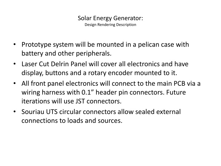
Solar Energy Generator: Design Rendering Description Prototype system will be mounted in a pelican case with battery and other peripherals. Laser Cut Delrin Panel will cover all electronics and have display, buttons and a rotary encoder mounted to it. All front panel electronics will connect to the main PCB via a wiring harness with 0.1 header pin connectors. Future iterations will use JST connectors. Souriau UTS circular connectors allow sealed external connections to loads and sources.
Solar Energy Generator: Front Panel Diagram Pelican Case Delrin Front Panel OLED Display Select Select Rotary Encoder Display Display Load Load Back Back Enter Enter Momentary Push Buttons
Solar Energy Generator: Internal case layout LiFePO4 Battery Pelican Case 5V Buck Module Port A Port C PCB Port B Port D I2C/SPI Isolator
Port Connections Souriau UTS 8 Pin connectors Ports A and B: Solar Panel Input, Battery Voltage output Ports C and D: Regulated 5V output, Battery Voltage output All connectors share the same body, but different pin locations are populated depending on function. Connection something to the wrong port wont cause any damage. Each port Contains locations for Panel+, Panel-, Battery V+, Regulated V+, GND, Control, and pins for future expansion with sensors and digital communication.
Solar Energy Generator: Final PCB Overview Power Stage Battery Terminal Panel Input Battery Temp, I2C Voltage + Current Sense Voltage + Current Sense Gate Drive Load Output 2 MCU 12V, 5V, 3.3V, 1.8V Regulators Load switch relays SPI, SCI, GPIO Load Output 1 De bounce Programming Buttons Display
Solar Energy Generator: A Usage Scenario Solar Panel Battery Serial Interface Microcontroller, Light sensor, Wireless radio LED Lamp
Solar Energy Generator: Final PCB 3D View