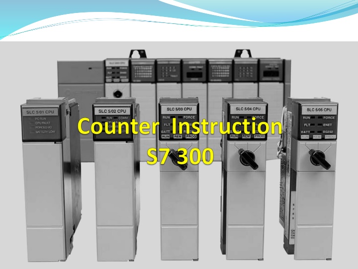
Mechanical Counters: Functionality and Resetting Processes
Mechanical counters operate similarly to programmed counters, adding a number each time the lever is activated before resetting to zero with a pushbutton. This system offers a practical and efficient means of tracking units or processes with its simple yet effective design. Explore the mechanisms behind mechanical counters and their applications in various industries.

Download Presentation

Please find below an Image/Link to download the presentation.
The content on the website is provided AS IS for your information and personal use only. It may not be sold, licensed, or shared on other websites without obtaining consent from the author.If you encounter any issues during the download, it is possible that the publisher has removed the file from their server.
You are allowed to download the files provided on this website for personal or commercial use, subject to the condition that they are used lawfully. All files are the property of their respective owners.
The content on the website is provided AS IS for your information and personal use only. It may not be sold, licensed, or shared on other websites without obtaining consent from the author.
E N D
Presentation Transcript
Mechanical counters can serve the same function as programmed counters Every time the actuating lever is moved over, the counter adds one number; the actuating lever then returns automatically to its original position Resetting to zero is done with a pushbutton located on the side of the unit Actuating lever 0000312 Reset button Mechanical counter
Electronic counters can count up, count down, or be combined to count up and down Although the majority of counters used in industry are up- counters, numerous applications require the implementation of down-counters or of combination up/ down-counters Electronic counters
All PLC manufacturers offer some form of counter instruction as part of their instruction set One common counter application is keeping track of the number of items moving past a given point PLC Counter application
The following counter instructions are available: S_CUD Up-Down Counter S_CD Down Counter S_CU Up Counter ---( SC ) Set Counter Coil ---( CU ) Up Counter Coil ---( CD ) Down Counter Coil
Counters have an area reserved for them in the memory of CPU This memory area reserves one 16-bit word for each counter address The ladder logic instruction set supports 256 counters The counter instructions are the only functions that have access to the counter memory area
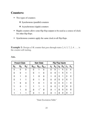
Bits 0 through 11 of the counter word contain the count value in binary code. The range of the count value is 0 to 999 A preset value should be entered in in the format: C#127
A positive edge transition at input S of the Up-Down Counter instruction sets the counter with the value at the Preset Value (PV) input A signal state of 1 at input R resets the counter. Resetting the counter places the value of the count at 0 The counter is incremented by 1 if the signal state at input CU changes from 0 to 1 and the value of the counter is less than 999 The counter is decremented by 1 if the signal state at input CD changes from 0 to 1 and the value of the counter is more than 0 If there is a positive edge at both count inputs, both operations are executed and the count remains the same
A positive edge transition at input S of the Up Counter instruction sets the counter with the value at the Preset Value (PV) input With a positive edge, the counter is reset at input R. The resetting of the counter sets the count value to 0 With a positive edge, the value of the counter at input CU is increased by 1 when the count value is less than 999 A signal state check for 1 at output Q produces a result of 1 when the count is greater than 0; the check produces a result of 0 when the count is equal to 0
This control application is designed to turn the red pilot light on and the green pilot light off after an accumulated count of 7 Ladder logic program C101 L1 Inputs PB1 (Count) Outputs L2 I1.0 M10.1 S_CU PB1 (Count) CU Q Rung 1 I1.0 I1.1 Red PL CV PB2 (Set value) PB2 (Set value) S Rung 2 Q2.0 R I1.2 I1.1 #7 PV CV_BCD PB3 (Reset) G Q2.1 PB3 (Reset) Rung 3 R Green PL I1.2 M10.1 Q2.0 Rung 4 Red PL Counter done bit M10.1 Q2.1 Rung 5 Green PL Counter done bit Simple up-counter program
T rue 1 2 3 4 5 6 7 Rung 1 (count) False Rung 2 (Preset value) Rung 4 Rung 5 Rung 3 (reset) 7 6 Preset 5 4 Accumulated value 3 2 1 Timing diagram
A positive edge transition at input S of the Down Counter instruction sets the counter with the value at the Preset Value (PV) input With a positive edge, the counter is reset at input R. The resetting of the counter sets the count value to 0 With a positive edge, the value of the counter at the input is reduced by 1 when the count value is greater than 0 A signal state check for 1 at output Q produces a result of 1 when the count is greater than 0; the check produces a result of 0 when the count is equal to 0
Set Counter Value executes only if there is a positive edge in RLO. At that time, the preset value transferred into the specified counter
Up Counter Coil increments the value of the specified counter by one if there is a positive edge in the RLO and the value of the counter is less than "999 If there is no positive edge in the RLO or the counter already has the value "999", the value of the counter will be unchanged
Down Counter Coil decrements the value of the specified counter by one, if there is a positive edge in the RLO state and the value of the counter is more than "0 If there is no positive edge in the RLO or the counter has already the value "0", the value of the counter will be unchanged