Counters and Time Delays in Electronics
COUNTERS
AND
TIME
DELAYS
PAVITHRA D.R ,BMSCW
•
A
counter
is
designed
simply
by
loading
appropriate
number
into
one
of
the registers
and
using
INR
or
DNR
instructions.
•
Loop
is
established
to
update
the
count.
•
Each
count
is
checked
to
determine
whether
it
has
reached
final
number
;if
not,
the
loop
is
repeated.
C
OUNTER
AND
T
IME
D
ELAYS
PAVITHRA D.R ,BMSCW
T
IME
D
ELAY
Procedure
used
to
design
a
specific
delay.
A
register
is
loaded
with
a
number
,
depending
on
the
time
delay
required
and
then
the register
is
decremented
until
it
reaches
zero
by
setting
up
a
loop
with
conditional
jump
instruction.
Time
delay
using
One
register:
PAVITHRA D.R ,BMSCW
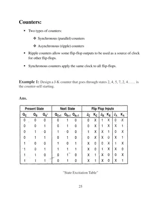
C
OMMENTS
T
Clock
frequency of the system = 2
MHz
Clock
period= 1/T= 0.5
μ
s
Time
to execute MVI = 7 T
states
* 0.5= 3.5
μ
s
Time
Delay in Loop T
L
= T*Loop T states *
N
10
= 0.5 * 14*
255
= 1785
μ
s
= 1.8
ms
N
10
= Equivalent
decimal number
of
hexadecimal
count loaded in the
delay
register
T
LA
=
Time
to execute loop
instructions
=T
L
–(3T
states* clock period)=1785-1.5=1783.5
μ
s
Note:
Total time delay Td= To+ TLA
To=T X outside loop T-states
PAVITHRA D.R ,BMSCW
PAVITHRA D.R ,BMSCW
Flowchart
fo
r
t
i
me
delay
with
two
loops
PAVITHRA D.R ,BMSCW
Flowchart
of
a
counter
with
time
delay
PAVITHRA D.R ,BMSCW
I
LLUSTRATIVE
P
ROGRAM
:
H
EXADECIMAL
C
OUNTER
Write
a
Program
to
count
continuously
from
FFH
to
00H
using
register
C
with
delay
count
8CH between
each
count
and
display
the
number
at
one
of
the
output
ports.
MVI
B,00H
DCR
B
MVI
C,8CH
NEXT:
DELAY:
DCR
C
JNZ
DELAY
MOV
A,B
OUT
PORT#
JMP
NEXT
PAVITHRA D.R ,BMSCW
I
LLUSTRATIVE
P
ROGRAM
: Z
ERO
TO
NINE
(M
ODULO
TEN
)
C
OUNTER
S
T
A
R
T
:
MVI
B,00H
MOV
A,B
DSPLAY:
OUT
PORT
#
LXI
H,16-bit
LO
O
P:
DCX H
MOV A,L
ORA H
JNZ
LOOP
INR B
MOV A,B
CPI
0AH
JNZ
DSPLAY
JZ
START
Start
Initialize counter
Display Output
Load Delay
register
Decrement Delay
register
Is Delay
register=0?
Next Count
Is count
=0AH?
If yes, Initialize
counter
If no, Display
Output
PAVITHRA D.R ,BMSCW
I
LLUSTRATIVE
P
ROGRAM
:
G
ENERATING
PULSE
WAVEFORMS
•
Generates
a
continuous
square
wave
with
the
period
of
500
Micro
Sec.
Assume
the system
clock period
is
325ns,
and
use
bit
D0
output
the square
wave.
PAVITHRA D.R ,BMSCW
Explore the fundamental concepts of counters and time delays in electronic systems as explained by Pavithra D.R. from BMSCW. Learn about the design and operation of counters, time delay procedures, label states, time delay using register pairs, flowcharts for time delays, and illustrative programming examples. Gain insights into implementing hexadecimal counters with specific delays and displaying output values. Enhance your knowledge of electronic circuits through detailed explanations and visual aids.

Download Presentation

Please find below an Image/Link to download the presentation.
The content on the website is provided AS IS for your information and personal use only. It may not be sold, licensed, or shared on other websites without obtaining consent from the author.If you encounter any issues during the download, it is possible that the publisher has removed the file from their server.
You are allowed to download the files provided on this website for personal or commercial use, subject to the condition that they are used lawfully. All files are the property of their respective owners.
The content on the website is provided AS IS for your information and personal use only. It may not be sold, licensed, or shared on other websites without obtaining consent from the author.
E N D
Presentation Transcript
COUNTERS AND TIME DELAYS PAVITHRA D.R ,BMSCW
COUNTER AND TIME DELAYS A counter is designed simply by loading appropriate number into one of the registers and using INR or DNR instructions. Loop is established to update the count. Each count is checked to determine whether it has reached final number ;if not, the loop is repeated. PAVITHRA D.R ,BMSCW
TIME DELAY Procedure used to design a specific delay. A register is loaded with a number , depending on the time delay required and decremented until it reaches zero by setting up a loop with conditional jump instruction. then the register is Time delayusing One register: PAVITHRA D.R ,BMSCW
LABEL STATES OPCODE OPERAND COMMENTS T MVI DCR JNZ C,FFH C LOOP ;Loadregister C ;DecrementC ;Jump backto 7 4 LOOP: 10/7 Clock frequency of the system = 2MHz Clock period= 1/T= 0.5 s Time to execute MVI = 7 T states * 0.5= 3.5 s Time Delay in Loop TL= T*Loop T states *N10 = 0.5 * 14* 255 = 1785 s = 1.8 ms N10 = Equivalent decimal number of hexadecimal count loaded in the delay register TLA= Time to execute loop instructions =TL (3T states* clock period)=1785-1.5=1783.5 s Note: Total time delay Td= To+ TLA To=T X outside loop T-states PAVITHRA D.R ,BMSCW
TIME DELAY USING A REGISTER PAIR Label Opcode LXI LOOP: DCX MOV ORA JNZ Operand B,2384H B A,C B LOOP Comments Load BC with 16-bit count Decrement BC by 1 Place contents of C inA OR B with C to set Zero flag if result not equal to 0 , jump back to loop T states 10 6 4 4 10/7 Time Delay in Loop TL= T*Loop T states *N10 = 0.5 * 24* 9092 = 109 ms Time Delay using a LOOP within a LOOP Delay in Loop TL1=1783.5 s Delay in Loop TL2=(0.5*21+TL1)*56 =100.46ms MVI B,38H MVI C,FFH DCR C JNZ LOOP1 DCR B JNZ LOOP2 7T 7T 4T 10/7 T 4T 10/7T LOOP2: LOOP1: PAVITHRA D.R ,BMSCW
Flowchart for time delay with two loops PAVITHRA D.R ,BMSCW
Flowchart of a counter with time delay PAVITHRA D.R ,BMSCW
ILLUSTRATIVE PROGRAM: HEXADECIMAL COUNTER Write a Program to count continuously from FFH to 00H using register C with delay count 8CH between each count and display the number at one of the output ports. MVI B,00H DCR B MVI C,8CH NEXT: DELAY: DCR C JNZ DELAY MOV A,B OUT PORT# JMP NEXT PAVITHRA D.R ,BMSCW
ILLUSTRATIVE PROGRAM: ZERO TO NINE (MODULO TEN) COUNTER Start START: MVI B,00H MOVA,B Initialize counter DSPLAY: OUT PORT# LXI H,16-bit LOOP: DCX H MOV A,L ORA H JNZ LOOP INR B MOV A,B CPI 0AH Display Output Load Delay register Decrement Delay register Is Delay register=0? Next Count JNZ DSPLAY JZ START Is count =0AH? If yes, Initialize counter If no, Display Output PAVITHRA D.R ,BMSCW
ILLUSTRATIVE PROGRAM: GENERATING PULSE WAVEFORMS Generates square wave with the period of 500 Micro Sec. Assume the system clock period is 325ns, and output the square wave. a continuous use bit D0 PAVITHRA D.R ,BMSCW