Sequential Counters in Digital Circuits
 undefined


Counters
Introduction: Counters
Counter
is a sequential circuit consisting of a set of flip-flops
which can go through sequence of states.
It is used to count the number of clock cycles.
Since the clock pulses occur at known intervals, the counter
can be used for measuring time such as period or frequency.
In addition to being a storage element, a flip-flop also can be
used as a counter by stacking flip-flops serially by connecting
series of flip-flops.
The counting depends on the number of counts or number of
distinct states the counter has.
Introduction: Counters
•
A counter is first described by a state diagram, which is
shows the sequence of states through which the counter
advances when it is clocked
.
Introduction: Counters
•
The circuit has no inputs other than the clock pulse.
•
No outputs other than its internal state (outputs are taken
off each flip-flop in the counter).
•
The next state of the counter depends entirely on its present
state, and the state transition occurs every time the clock
pulse occurs.
Introduction: Counters
•
Once the sequential circuit is defined by the state
diagram, the next step is to obtain the next-state table,
which is derived from the state diagram
Introduction: Counters
The number of distinct states the counter can take is 2
N
. It
depends on the number of flip-flops that the counter has.
There are two types of counting namely Up counting & Down
counting
In Up counting, If start the count with 0, the number of states
will go to 2
N-1
In Down counting, the count starts from 2
N-1
to 0.
Let us assume that there are three flip-flops have the outputs
A B C as QA QB and QC and the count starts from 0 0 0
then 0 0 1 .... 0 1 1.
The complementary outputs (Q bar) Q’A Q’B and Q’C and
this would start from 1 1 1, 1 1 0 .... 000.
Introduction: Counters
When take the output from Q, it becomes up counting as well
as the output of Q’ or Q bar becomes down counting.
So it is a very major use of Flip-flops, (i.e.)
use flip-flops in a
chain and for counting events.
If counter start from 000 to 111 and then again from 000, it is
referred to full cycle.
The total number of states the counter has is called
MODULO or MODULUS.
Sometimes, not want to count till the end of the last state or
want to terminate the count at the count which is less than
maximum and go back to 0.
Introduction: Counters
For example, the counter has four bits and it has 0 to 15
states and may want to terminate with 9 that is 0 to 9
and start again with 0, there will be a decimal counter.
By using this decimal counter,
able to start at any count
or end at any count within the possible range.
Asynchronous (Ripple) Counters
When the output of a flip-flop is used as the clock input for
the next flip-flop, the counter is referred to as
ripple counter
or
asynchronous counter
.
Asynchronous counters
: the flip-flops do not change states at
exactly the same time as they do not have a common clock
pulse.
In
ripple counters
, the input clock pulse “ripples” through the
counter – the drawback is cumulative delay.
A counter has a natural count of 2
n
where n is the number of
FFs in the counter.
Counter can operate in either a count-up or count-down
mode.
Digital clock is an typical application for counters.
Asynchronous (Ripple) Counters
•
A binary ripple counter can be constructed using clocked JK FFs.
•
The following figure shown Negative Edge Triggered, JK FFs connected in cascade.
•
The system clock drives FF A. The output of A drives B, the output of B drives FF C.
•
A
l
l
t
h
e
J
&
K
i
n
p
u
t
s
a
r
e
t
i
e
d
t
o
+
V
c
c
.
T
h
i
s
m
e
a
n
s
t
h
a
t
e
a
c
h
F
F
w
i
l
l
c
h
a
n
g
e
s
t
a
t
e
w
i
t
h
a
N
T
a
t
i
t
s
c
l
o
c
k
i
n
p
u
t
.
Asynchronous (Ripple) Counters
In ripple or asynchronous counter, the A FF must change state
before it can trigger the B FF and the B FF has to change state
before it can trigger the C FF.
The triggers move through the FFs like a ripple in water.
Because of this, the overall propagation delay time is the sum
of the individual delays.
For instance, if each FF in this three FF counter has a
propagation delay time of 10 ns, the overall propagation delay
time for the counter is 30 ns.
Asynchronous (Ripple) Counters
•
A binary ripple counter counts in a straight binary sequence.
•
If a counter has n flip flop, will have 2n output conditions (000
through 111).
•
If 5 FFs and then 32 output conditions (00000 through 11111).
•
A 3-bit FF counter is often referred to as a modulus-8 (or
mod-8) counter since it has eight states.
•
Similarly, a 4 FF counter is a mod-16 counter and a six FF
counter is mod-64 counter.
•
The modulus of a counter is the total number of states
through which the counter can progress.
Ripple Down Counter
[3-bit ripple counter]
The system clock is still used at the clock input to FF a, but
the complement of A, A’ is used to drive FF B, likewise, B’ is
used to drive FF C.
Ripple Up-Down Counter
•
A 3-bit asynchronous up-down counter that counts in a straight binary sequence is
shown below.
•
It is simply a combination of the two counters discussed previously.
•
For this, counter to progress through a count-up sequence, it is necessary to
trigger each FF with the true side of the previous FF (as opposed to the
complement side).
•
If the count-down control line is low and count-up control line high, and the counter
will have count-up wave forms.
•
On the other hand, if count-down is high and count-up is low, each FF will be
triggered from the complement side of the previous FF.
•
The counter will then be in a count-down mode and will progress through the
waveforms.
Synchronous (Parallel) Counters
Asynchronous counters are not useful at very high
frequencies, especially for counters with large number of
bits.
Another problem caused by propagation delays in
asynchronous counts occurs when try to electronically
detect (decode) the counter outputs states.
Both of these problems can be overcome by the use of a
synchronous or parallel counter.
Synchronous (Parallel) Counters
Synchronous (parallel) counters
:
the clock inputs of all the flip-flops are
connected together and are triggered by the input pulses.
Clock pulses are applied to the input of all FFs.
All the flip-flops change state simultaneously (in parallel).
T=0 or J=K=0 (FF does not change state)
T=1 or J=K=1 (FF complements)
Design these counters using the sequential logic design process.
Example: 2-bit synchronous binary counter (using T flip-flops, or JK flip-
flops with identical J,K inputs).
Synchronous (Parallel) Counters
Example: 3-bit synchronous binary counter.
TA
2
= A
1
.A
0
TA
1
= A
0
TA
0
=
1
Synchronous (Parallel) Counters
Note that in a binary counter, the n
th
bit (shown
underlined) is always complemented whenever
0
11…11
1
00…00
or
1
11…11
0
00…00
Synchronous (Parallel) Counters
Example: 4-bit synchronous binary counter.
TA
3
=
A
2
.
A
1
.
A
0
TA
2
=
A
1
.
A
0
TA
1
=
A
0
TA
0
= 1
Up/Down Synchronous Counters
Up/down synchronous counter
: a
bidirectional
counter that is capable of counting either up or
down.
An input (control) line
Up
/
Down
(or simply
Up
)
specifies the direction of counting.
Up
/
Down
= 1
Count upward
Up
/
Down
= 0
Count downward
Up/Down Synchronous Counters
Example: A 3-bit up/down synchronous binary
counter.
Up/Down Synchronous Counters
Example: A 3-bit up/down synchronous binary
counter (cont’d).
TQ
0
= 1
TQ
1
= (
Q
0
.
Up
) + (
Q
0
'
.
Up'
)
TQ
2
= (
Q
0
.
Q
1
.
Up
)
+ (
Q
0
'
.
Q
1
'
.
Up'
)
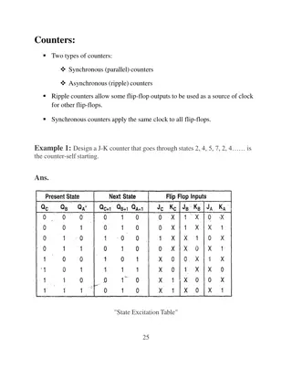
Sequential counters, comprised of flip-flops, are essential in digital circuits for counting clock cycles. They advance through states based on clock pulses and can measure time intervals. The circuit's output state solely depends on its present state, with transitions occurring at each clock pulse. Different counting modes like Up and Down counting, along with state diagrams and next-state tables, play crucial roles in defining counter behavior. The number of distinct states in a counter is determined by the number of flip-flops used. By utilizing these concepts, counters can fulfill various counting needs efficiently.

Download Presentation

Please find below an Image/Link to download the presentation.
The content on the website is provided AS IS for your information and personal use only. It may not be sold, licensed, or shared on other websites without obtaining consent from the author.If you encounter any issues during the download, it is possible that the publisher has removed the file from their server.
You are allowed to download the files provided on this website for personal or commercial use, subject to the condition that they are used lawfully. All files are the property of their respective owners.
The content on the website is provided AS IS for your information and personal use only. It may not be sold, licensed, or shared on other websites without obtaining consent from the author.
E N D
Presentation Transcript
Introduction: Counters Counter is a sequential circuit consisting of a set of flip-flops which can go through sequence of states. It is used to count the number of clock cycles. Since the clock pulses occur at known intervals, the counter can be used for measuring time such as period or frequency. In addition to being a storage element, a flip-flop also can be used as a counter by stacking flip-flops serially by connecting series of flip-flops. The counting depends on the number of counts or number of distinct states the counter has.
Introduction: Counters A counter is first described by a state diagram, which is shows the sequence of states through which the counter advances when it is clocked.
Introduction: Counters The circuit has no inputs other than the clock pulse. No outputs other than its internal state (outputs are taken off each flip-flop in the counter). The next state of the counter depends entirely on its present state, and the state transition occurs every time the clock pulse occurs.
Introduction: Counters Once the sequential circuit is defined by the state diagram, the next step is to obtain the next-state table, which is derived from the state diagram
Introduction: Counters The number of distinct states the counter can take is 2N. It depends on the number of flip-flops that the counter has. There are two types of counting namely Up counting & Down counting In Up counting, If start the count with 0, the number of states will go to 2N-1 In Down counting, the count starts from 2N-1 to 0. Let us assume that there are three flip-flops have the outputs A B C as QA QB and QC and the count starts from 0 0 0 then 0 0 1 .... 0 1 1. The complementary outputs (Q bar) Q A Q B and Q C and this would start from 1 1 1, 1 1 0 .... 000.
Introduction: Counters When take the output from Q, it becomes up counting as well as the output of Q or Q bar becomes down counting. So it is a very major use of Flip-flops, (i.e.) use flip-flops in a chain and for counting events. If counter start from 000 to 111 and then again from 000, it is referred to full cycle. The total number of states the counter has is called MODULO or MODULUS. Sometimes, not want to count till the end of the last state or want to terminate the count at the count which is less than maximum and go back to 0.
Introduction: Counters For example, the counter has four bits and it has 0 to 15 states and may want to terminate with 9 that is 0 to 9 and start again with 0, there will be a decimal counter. By using this decimal counter, able to start at any count or end at any count within the possible range.
Asynchronous (Ripple) Counters When the output of a flip-flop is used as the clock input for the next flip-flop, the counter is referred to as ripple counter or asynchronous counter. Asynchronous counters: the flip-flops do not change states at exactly the same time as they do not have a common clock pulse. In ripple counters, the input clock pulse ripples through the counter the drawback is cumulative delay. A counter has a natural count of 2n where n is the number of FFs in the counter. Counter can operate in either a count-up or count-down mode. Digital clock is an typical application for counters.
Asynchronous (Ripple) Counters A binary ripple counter can be constructed using clocked JK FFs. The following figure shown Negative Edge Triggered, JK FFs connected in cascade. The system clock drives FF A. The output of A drives B, the output of B drives FF C. All the J & K inputs are tied to +Vcc. This means that each FF will change state with a NT at its clock input.
Asynchronous (Ripple) Counters In ripple or asynchronous counter, the A FF must change state before it can trigger the B FF and the B FF has to change state before it can trigger the C FF. The triggers move through the FFs like a ripple in water. Because of this, the overall propagation delay time is the sum of the individual delays. For instance, if each FF in this three FF counter has a propagation delay time of 10 ns, the overall propagation delay time for the counter is 30 ns.
Asynchronous (Ripple) Counters A binary ripple counter counts in a straight binary sequence. If a counter has n flip flop, will have 2n output conditions (000 through 111). If 5 FFs and then 32 output conditions (00000 through 11111). A 3-bit FF counter is often referred to as a modulus-8 (or mod-8) counter since it has eight states. Similarly, a 4 FF counter is a mod-16 counter and a six FF counter is mod-64 counter. The modulus of a counter is the total number of states through which the counter can progress.
Ripple Down Counter [3-bit ripple counter] The system clock is still used at the clock input to FF a, but the complement of A, A is used to drive FF B, likewise, B is used to drive FF C.
Ripple Up-Down Counter A 3-bit asynchronous up-down counter that counts in a straight binary sequence is shown below. It is simply a combination of the two counters discussed previously. For this, counter to progress through a count-up sequence, it is necessary to trigger each FF with the true side of the previous FF (as opposed to the complement side). If the count-down control line is low and count-up control line high, and the counter will have count-up wave forms. On the other hand, if count-down is high and count-up is low, each FF will be triggered from the complement side of the previous FF. The counter will then be in a count-down mode and will progress through the waveforms.
Synchronous (Parallel) Counters Asynchronous counters are not useful at very high frequencies, especially for counters with large number of bits. Another problem caused by propagation delays in asynchronous counts occurs when try to electronically detect (decode) the counter outputs states. Both of these problems can be overcome by the use of a synchronous or parallel counter.
Synchronous (Parallel) Counters Synchronous (parallel) counters: the clock inputs of all the flip-flops are connected together and are triggered by the input pulses. Clock pulses are applied to the input of all FFs. All the flip-flops change state simultaneously (in parallel). T=0 or J=K=0 (FF does not change state) T=1 or J=K=1 (FF complements) Design these counters using the sequential logic design process. Example: 2-bit synchronous binary counter (using T flip-flops, or JK flip- flops with identical J,K inputs). Present state A1 A0A1 0 0 0 1 1 0 1 1 Next state +A0 0 1 1 0 00 01 + 1 0 1 0 11 10
Synchronous (Parallel) Counters Example: 3-bit synchronous binary counter. TA2 = A1.A0 TA1 = A0 TA0 = 1 A2 A1 A0 Q Q Q J K J K J K CP 1
Synchronous (Parallel) Counters Note that in a binary counter, the nth bit (shown underlined) is always complemented whenever 011 11 100 00 or 111 11 000 00
Synchronous (Parallel) Counters Example: 4-bit synchronous binary counter. TA3 = A2 . A1. A0 TA2 = A1. A0 TA1 = A0 TA0 = 1 A1.A0 A2.A1.A0 1 A0 A1 A2 A3 J J J J Q Q Q Q Q C C C C Q' Q' Q' Q' Q' K K K K CLK
Up/Down Synchronous Counters Up/down synchronous counter: a bidirectional counter that is capable of counting either up or down. An input (control) line Up/Down (or simply Up) specifies the direction of counting. Up/Down = 1 Count upward Up/Down = 0 Count downward
Up/Down Synchronous Counters Example: A 3-bit up/down synchronous binary counter. Clock pulse 0 1 2 3 4 5 6 7 Q2 0 0 0 0 1 1 1 1 Q1 0 0 1 1 0 0 1 1 Q0 0 1 0 1 0 1 0 1 Up Down Up counter TQ0 = 1 TQ1 = Q0 TQ2 = Q0.Q1 Down counter TQ0 = 1 TQ1 = Q0 TQ2 = Q0 .Q1
Up/Down Synchronous Counters Example: A 3-bit up/down synchronous binary counter (cont d). TQ0 = 1 TQ1 = (Q0.Up) + (Q0'.Up' ) TQ2 = ( Q0.Q1.Up )+ (Q0'. Q1'. Up' ) Q0 Q1 Q2 1 T T T Q Q Q Q Q Q Up C C C Q' Q' Q' Q' Q' Q' CLK


 Counters")
 Counters")
 Counters")
 Counters")


 Counters")
 Counters")
 Counters")
 Counters")
 Counters")