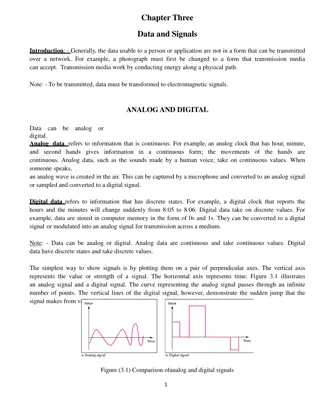
Lab 4: Analog-to-Digital Converter
Explore sample codes for Analog-to-Digital Converter (ADC) implementations in embedded systems. Learn how to perform single and continuous conversions, interact with pins, use timers for sampling, and enable interrupts. The provided code snippets demonstrate practical applications in ADC programming for embedded systems at National Tsing Hua University.

Download Presentation

Please find below an Image/Link to download the presentation.
The content on the website is provided AS IS for your information and personal use only. It may not be sold, licensed, or shared on other websites without obtaining consent from the author.If you encounter any issues during the download, it is possible that the publisher has removed the file from their server.
You are allowed to download the files provided on this website for personal or commercial use, subject to the condition that they are used lawfully. All files are the property of their respective owners.
The content on the website is provided AS IS for your information and personal use only. It may not be sold, licensed, or shared on other websites without obtaining consent from the author.
E N D
Presentation Transcript
CS4101 Introduction to Embedded Systems Lab 4: Analog-to-Digital Converter Prof. Chung-Ta King Department of Computer Science National Tsing Hua University, Taiwan National Tsing Hua University
Sample Code 1 for ADC10 Repetitive single conversion: Repetitively perform single samples on A1 (pin P1.1) with reference to Vcc If A1 > 0.5*Vcc, P1.0 set, else reset. Set ADC10SC to start sample and conversion But ADC10SC automatically cleared at end of conversion. Enable the next conversion in ISR of ADC10 and iterate Use ADC10 internal oscillator to time the sample and conversion 1 National Tsing Hua University
Sample Code 1 for ADC10 void main(void) { WDTCTL = WDTPW + WDTHOLD; // Stop WDT // H&S time 16x, interrupt enabled ADC10CTL0 = ADC10SHT_2 + ADC10ON + ADC10IE; ADC10CTL1 = INCH_1; // Input from A1 ADC10AE0 |= 0x02; // Enable pin A1 for analog in P1DIR |= 0x01; // Set P1.0 to output ADC10CTL0 |= ENC + ADC10SC; // Start sampling for (;;) { } } #pragma vector=ADC10_VECTOR __interrupt void ADC10_ISR(void) { if (ADC10MEM < 0x1FF) P1OUT &= ~0x01; else P1OUT |= 0x01; ADC10CTL0 |= ENC + ADC10SC; // enable sampling } 2 National Tsing Hua University
Sample Code 2 for ADC10 Continuous sampling driven by Timer0_A3 A1 is sampled 16/second with reference to 1.5V, where ACLK runs at 32 KHz driven by an external crystal (2048 ACLK cycles give 1/16 second (ACLK/2048)) If A1 > 0.5V, P1.0 is set, else reset. Timer0_A3 is run in up mode with CCR0 defining the sampling period (2048 cycles) Use CCR1 to automatically trigger ADC10 conversion 3 National Tsing Hua University
Sample Code 2 for ADC10 #include msp430.h int i=1; void main(void) { WDTCTL = WDTPW + WDTHOLD; // Stop WDT // TA1 trigger sample start ADC10CTL1 = SHS_1 + CONSEQ_2 + INCH_1; ADC10CTL0 = SREF_1 + ADC10SHT_2 + REFON + ADC10ON + ADC10IE; __enable_interrupt(); // Enable interrupts TA0CCR0 = 30; // Delay for Volt Ref to settle TA0CCTL0 |= CCIE; // Compare-mode interrupt TA0CTL = TASSEL_2 + MC_1; // SMCLK, Up mode while(i); // Wait for settle TA0CCTL0 &= ~CCIE; // Disable timer Interrupt __disable_interrupt(); How to break? 4 National Tsing Hua University
Sample Code 2 for ADC10 ADC10CTL0 |= ENC; // ADC10 Enable ADC10AE0 |= 0x02; // P1.1 ADC10 option select P1DIR |= 0x01; // Set P1.0 output TA0CCR0 = 2048-1; // Sampling period TA0CCTL1 = OUTMOD_3; // TACCR1 set/reset TA0CCR1 = 2046; // TACCR1 OUT1 on time TA0CTL = TASSEL_1 + MC_1; // ACLK, up mode while(1); } Timer0_A CCR1 out mode 3: The output (OUT1) is set when the timer counts to the TA0CCR1 value and is reset when the timer counts to the TA0CCR0 value. 5 National Tsing Hua University
Sample Code 2 for ADC10 // ADC10 interrupt service routine #pragma vector=ADC10_VECTOR __interrupt void ADC10_ISR(void){ if (ADC10MEM < 0x155) // ADC10MEM = A1 > 0.5V? P1OUT &= ~0x01; // Clear P1.0 LED off else P1OUT |= 0x01; // Set P1.0 LED on } #pragma vector=TIMERA0_VECTOR __interrupt void ta0_isr(void){ TA0CTL = 0; i = 0; } Break the while loop in main() that waits for the internal voltage reference to settle 6 National Tsing Hua University
Lab 4 Basic 1: Flash the red and green LED alternatively on interrupts from button releases. The LEDs flash at 1 Hz (0.3 sec on and 0.7 sec off) by interrupts (ACLK sourced from VLO). Every time the button is pushed, measure the temperature once, convert it to Celsius and store in a variable. Show the value of the variable in the debug mode of CCS. Use 1.5V voltage reference, the single-channel-single- conversion mode, and the triggering source of ADC10SC. Hint: V = 0.00355 * C + 0.986, where V is Voltage and C is Celsius If voltage >= 1.125V, change LED flash frequency to 2 Hz (0.3 sec on and 0.2 sec off); otherwise, back to 1 Hz. 7 National Tsing Hua University
Lab 4 Basic 2: When the button is up, neither of the LEDs is on. When the button is down, only flash the green LED at 1 Hz (0.3 sec on and 0.7 sec off) with ACLK sourced from VLO. While the button is pressed, measure the temperature every 0.5 sec, using repeat-single-conversion mode triggered continuously by Timer0_A3. If the average temperature of the last second rises, then flash the red LED instead (on for 0.2 sec and off for 0.8 sec), which is controlled by Timer1_A3 driven by SMCLK sourced by DCO. Otherwise, flash the green LED as specified above. All events must be detected and handled by interrupts. 8 National Tsing Hua University