Keystone I Boot Procedure Introduction


K
e
y
s
t
o
n
e
I
B
o
o
t
P
r
o
c
e
d
u
r
e
I
n
t
r
o
d
u
c
t
i
o
n
1
C
h
i
n
a
M
u
l
t
i
c
o
r
e
A
p
p
l
i
c
a
t
i
o
n
M
a
r
,
2
0
1
4

A
g
e
n
d
a
•
Keystone I Boot Overview
•
Rom Boot Loader
•
Intermediate Boot Loader
2
K
e
y
s
t
o
n
e
I
D
S
P
F
a
m
i
l
y
3
C667x
•
Fixed/Float 32-bit
DSP (up to 8 cores)
up to 320 GMAC/160
GFLOP @ 1.25GHz
•
32KB L1P
•
32KB L1D
•
512KB L2 Per Core
•
4MB Shared L2
•
72-Bit DDR3-1333
•
Network
Coprocessor
•
Multicore Navigator
•
SYS/BIOS, Multicore
SDK
C665x
•
Fixed/Float 32-bit
DSP (up to 8 cores)
up to 320 GMAC/160
GFLOP @ 1.25GHz
•
32KB L1P
•
32KB L1D
•
1MB L2 Per Core
•
1MB Shared L2
•
32-Bit DDR3-1333
•
Multicore Navigator
•
Power Optimized
•
SYS/BIOS, Multicore
SDK
C6670
•
Fixed/Float 32-bit
DSP (4 cores) up to
160 GMAC/80
GFLOP @ 1.25GHz
•
32KB L1P
•
32KB L1D
•
1MB L2 Per Core
•
2MB Shared L2
•
72-Bit DDR3-1333
•
Network
Coprocessor
•
Wireless Application
Accelerators
•
Multicore Navigator
•
SYS/BIOS, Multicore
SDK
R
e
s
e
t
T
y
p
e
s
4
D
i
f
f
e
r
e
n
t
B
o
o
t
I
m
a
g
e
L
o
c
a
t
i
o
n
5
•
Storage
–
NAND Flash
–
NOR Flash
–
EEPROM
–
FTP
•
Host knows
memory map of the
boot device
–
SRIO DIO
–
I2C
–
Hyperlink
–
PCIE
•
Host do not knows
memory map of the
boot device
–
SRIO Message
–
EMAC
–
UART
R
B
L
a
n
d
I
B
L
•
Rom Boot Loader
–
RBL is a code used directly for
the device startup
–
RBL code is burned in the DSP
ROM (Non-modifiable)
–
Base address for the RBL is
0x20B00000
–
Supported boot mode is fixed
6
•
Intermediate Boot Loader
–
IBL is a code used for second-
stage boot after RBL
–
IBL code is always burned in
the I2C EEPROM and can be
modified by customers
–
Base address for the IBL is in
L2 or SL2 memory.
–
Supported boot mode is easy
to extend.
Rom Boot Loader
Intermediate Boot Loader
A
g
e
n
d
a
•
Keystone I Boot Overview
•
Rom Boot Loader
•
Intermediate Boot Loader
7
R
B
L
P
r
o
c
e
s
s
8
Boot Start
Hiber
Enabled
Check
Hibernation
Latch Boot
Mode Pins
Boot
Parameter
Table Init
PLL
Required
?
POR
Reset
Branch to
PWRSTATCTL
Branch to boot
function
PLL bypassed
Boot Mode
Specific
Process
Initialize the
PLLs
Y
E
S
N
O
N
O
Y
E
S
Y
E
S
N
O
B
o
o
t
M
o
d
e
P
i
n
•
Boot mode and configurations are chosen using bootstrap pins on the device.
–
Pins are latched and stored in13 bits of the DEVSTAT register during POR.
•
The configuration format for these 13 bits are shown in the table:
•
Boot Device [2:0] is dedicated for selecting the boot mode
•
Device Configuration [9:3] is used to specify the boot mode specific configurations.
•
PLL Multi [12:10] are used for PLL selection. In case of I2C/SPI boot mode, it is used
for extended device configuration. (PLL is bypassed for these two boot modes)
9
R
B
L
B
o
o
t
M
o
d
e
s
•
I2C Boot
–
Master Boot (from I2C EEPROM)
–
Master-Broadcast Boot(Master Boot followed by broadcast to slave cores)
–
Passive Boot (external I2C host)
•
SPI Boot (from SPI flash)
•
SRIO Boot (from external host connected through SRIO, DIO or Message)
•
Ethernet Boot (boot from external host connected through Ethernet)
•
PCIe Boot (boot from external host connected through PCIe )
•
HyperLink Boot (boot from external host connected through HyperLink)
•
EMIF16 NOR Boot (boot from NOR Flash)
–
Device Manual will detail supported types.
–
C665x have NAND boot as well
10
B
o
o
t
T
a
b
l
e
•
The image to be loaded into the device is
converted to Boot Table recognizable by
the RBL.
•
Code and data sections are inserted into
the boot table automatically by the HEX
conversion utility.
11
B
o
o
t
C
o
n
f
i
g
u
r
a
t
i
o
n
T
a
b
l
e
•
A boot configuration table is used to
program peripheral registers.
•
For example, DDR initilization…
•
Each table entry in the boot configuration
table has three elements:
–
The address to be modified
–
The set mask
–
The clear mask
12
I
2
C
M
a
s
t
e
r
•
Uses 7 bits of device in Master
Mode
•
Make the initial read of the I2C
EEPROM while PLL is in
bypass.
•
The initial boot parameter
table will contain the desired
clock multiplier which will be
setup prior to any subsequent
reads.
13
I
2
C
P
a
s
s
i
v
e
•
Uses 5 bits of device
configuration
•
Does not drive the clock, but
simply received on the
specified address.
•
The I2C address is calculated
by adding 0x19 to the I2C
address specified in the
device configuration.
14
S
P
I
•
RBL reads either a boot
parameter table or boot
table from SPI flash
•
The table loaded can
contain a boot parameter
table for any other boot
mode.
15
E
M
I
F
1
6
•
Used to boot from the NOR
flash.
•
RBL configures the EMIF16
, sets the boot complete bit
and branches to EMIF16
CS2 data memory at
0x70000000.
•
No Memory is reserved by
the boot loader.
16
E
t
h
e
r
n
e
t
•
Ethernet(SGMII) boot
configuration sets SERDES
clock and device ID.
17
S
R
I
O
•
SRIO boot configuration
sets the Clock, Lane
configuration, and mode
18
P
C
I
-
E
•
In PCIe mode,
most PCIE
configuration registers
should be setup by host
remotely.
•
And then the host loads all
the sections directly to the
memory.
19
H
y
p
e
r
l
i
n
k
•
HyperLink boot mode boots
the DSP through the ultra
short range HyperLink.
•
The host loads the boot
image directly through the
link and then generates the
interrupt to wake the DSP.
20
B
o
o
t
M
u
l
t
i
c
o
r
e
•
During the boot process, the boot loader code is loaded into the L2 of corePac0 from
the ROM.
•
The high 0xD23F (52K) bytes of L2 in all corePacs are reserved for the boot code.
User should not overwrite this area.
•
All the other Cores will execute an IDLE.
•
User should load the image into the L2 of CorePacs they want to boot up.
•
Before setting the boot complete register, the user should also set the start address of
the code in the respective BOOT MAGIC ADDRESS of the CorePac L2.
•
Finally, the user image should also write the IPC interrupt register to bring the required
corePacs out of IDLE.
21
A
g
e
n
d
a
•
Keystone I Boot Overview
•
Rom Boot Loader
•
Intermediate Boot Loader
22
W
h
y
I
B
L
?
•
Boot from Nand flash on C667x/C6670
•
Boot from FTP server
•
Boot from images with different format
•
Boot from multiple images
•
Extended functions before boot
23
I
B
L
S
u
p
p
o
r
t
Default device
•
Nand Flash
•
Nor Flash
•
TFTP
24
Image Format
•
ELF
•
BBLOB
E
a
s
y
t
o
U
s
e
•
Compile IBL source code in MCSDK directory
•
Burn IBL and parameter set to I2C EEPROM
•
Generate user image
•
Burn user image to Nand/Nor or upload to FTP server
•
Set boot mode pin on DSP
•
Power on DSP
25
R
e
f
e
r
e
n
c
e
•
KeyStone Architecture Bootloader User Guide
•
TMS320C667x/0(C665x) Multicore Fixed and Floating-Point Digital Signal Processor
Data Manual
•
BIOS-MCSDK User Guide
•
http://processors.wiki.ti.com/index.php/MAD_Utils_User_Guide
•
http://linux-c6x.org/wiki/index.php/IBL_version_1.0.0.11
•
www.deyisupport.com
26
B
a
c
k
u
p
27
Boot procedure introduction for Keystone I multicore DSP application. Learn about ROM boot loader, intermediate boot loader, DSP family details, reset types, different boot image locations, and RBL/IBL functionalities. Gain insights into boot modes, memory maps, and code burning processes for efficient device startup and customization.

Download Presentation

Please find below an Image/Link to download the presentation.
The content on the website is provided AS IS for your information and personal use only. It may not be sold, licensed, or shared on other websites without obtaining consent from the author.If you encounter any issues during the download, it is possible that the publisher has removed the file from their server.
You are allowed to download the files provided on this website for personal or commercial use, subject to the condition that they are used lawfully. All files are the property of their respective owners.
The content on the website is provided AS IS for your information and personal use only. It may not be sold, licensed, or shared on other websites without obtaining consent from the author.
E N D
Presentation Transcript
Keystone I Boot Procedure Introduction China Multicore Application Mar, 2014 TI Information Selective Disclosure TI Information Selective Disclosure 1
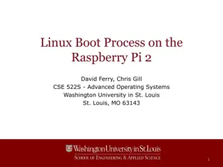
Agenda Keystone I Boot Overview Rom Boot Loader Intermediate Boot Loader TI Information Selective Disclosure 2
Keystone I DSP Family C665x C667x C6670 Fixed/Float 32-bit DSP (up to 8 cores) up to 320 GMAC/160 GFLOP @ 1.25GHz 32KB L1P 32KB L1D 1MB L2 Per Core 1MB Shared L2 32-Bit DDR3-1333 Multicore Navigator Power Optimized SYS/BIOS, Multicore SDK Fixed/Float 32-bit DSP (up to 8 cores) up to 320 GMAC/160 GFLOP @ 1.25GHz 32KB L1P 32KB L1D 512KB L2 Per Core 4MB Shared L2 72-Bit DDR3-1333 Network Coprocessor Multicore Navigator SYS/BIOS, Multicore SDK Fixed/Float 32-bit DSP (4 cores) up to 160 GMAC/80 GFLOP @ 1.25GHz 32KB L1P 32KB L1D 1MB L2 Per Core 2MB Shared L2 72-Bit DDR3-1333 Network Coprocessor Wireless Application Accelerators Multicore Navigator SYS/BIOS, Multicore SDK TI Information Selective Disclosure 3
Reset Types Reset Types Initiator Exception Boot Pin Boot Process POR (Power On Reset) POR active low RESETFULL active low Latched and update None(Reset everything on DSP) Yes RESET active low Emulation PLLCTL register Watchdog timers Test/emu logic Reset isolation modules Hard Reset No Yes Test/emu logic reset isolation modules EMIF16 MMRs, DDR3 EMIF MMRs, the sticky bits in PCIe MMRs RESET active low PLLCTL register (RSCTRL) Watchdog timers Soft Reset No Yes Software (through LPSC MMR) Watchdog timers LRESET pin C66x CorePac local reset Only Reset CorePac without destroying memory No No TI Information Selective Disclosure 4
Different Boot Image Location Host knows memory map of the boot device SRIO DIO I2C Hyperlink PCIE Host do not knows memory map of the boot device SRIO Message EMAC UART Storage NAND Flash NOR Flash EEPROM FTP TI Information Selective Disclosure 5
RBL and IBL Intermediate Boot Loader Intermediate Boot Loader Rom Boot Loader Rom Boot Loader IBL is a code used for second- stage boot after RBL IBL code is always burned in the I2C EEPROM and can be modified by customers Base address for the IBL is in L2 or SL2 memory. Supported boot mode is easy to extend. RBL is a code used directly for the device startup RBL code is burned in the DSP ROM (Non-modifiable) Base address for the RBL is 0x20B00000 Supported boot mode is fixed TI Information Selective Disclosure 6
Agenda Keystone I Boot Overview Rom Boot Loader Intermediate Boot Loader TI Information Selective Disclosure 7
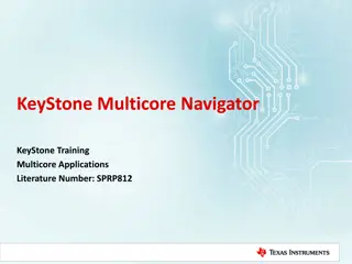
RBL Process Check Hibernation Hiber Enabled YES Branch to PWRSTATCTL NO NO Boot PLL POR Reset YES Branch to boot function NO Boot Start Parameter Table Init Required ? PLL bypassed YES Boot Mode Specific Process Latch Boot Mode Pins Initialize the PLLs TI Information Selective Disclosure 8
Boot Mode Pin Boot mode and configurations are chosen using bootstrap pins on the device. Pins are latched and stored in13 bits of the DEVSTAT register during POR. The configuration format for these 13 bits are shown in the table: Boot Mode Pins 12 11 10 9 8 7 PLL Mult I2C/SPI Ext Dev Cfg 6 5 4 3 2 1 0 Device Configuration Boot Device Boot Device [2:0] is dedicated for selecting the boot mode Device Configuration [9:3] is used to specify the boot mode specific configurations. PLL Multi [12:10] are used for PLL selection. In case of I2C/SPI boot mode, it is used for extended device configuration. (PLL is bypassed for these two boot modes) TI Information Selective Disclosure 9
RBL Boot Modes I2C Boot Master Boot (from I2C EEPROM) Master-Broadcast Boot(Master Boot followed by broadcast to slave cores) Passive Boot (external I2C host) SPI Boot (from SPI flash) SRIO Boot (from external host connected through SRIO, DIO or Message) Ethernet Boot (boot from external host connected through Ethernet) PCIe Boot (boot from external host connected through PCIe ) HyperLink Boot (boot from external host connected through HyperLink) EMIF16 NOR Boot (boot from NOR Flash) Device Manual will detail supported types. C665x have NAND boot as well TI Information Selective Disclosure 10
Boot Table 32-bit Program Entrance The image to be loaded into the device is converted to Boot Table recognizable by the RBL. 32-bit Section Length 32-bit Section Address Code and data sections are inserted into the boot table automatically by the HEX conversion utility. Section Data 32-bit Section Length 32-bit Section Address Section Data 0x00000000 (Boot Table End) TI Information Selective Disclosure 11
Boot Configuration Table A boot configuration table is used to program peripheral registers. For example, DDR initilization Each table entry in the boot configuration table has three elements: The address to be modified The set mask The clear mask Address Entry 0 Set Mask Clear Mask Address Entry 1 Set Mask Clear Mask Set Mask Bit Clear Mask Bit Operation 0x00000000 0 1 0 1 0 0 1 1 Unchange Set Clear Toggle Entry N Termination 0x00000000 0x00000000 TI Information Selective Disclosure 12
I2C Master Uses 7 bits of device in Master Mode I2C Master Mode Device Configuration Bit Fields 9 8 Address Rsvd Mode (0) 12 11 10 7 6 5 4 3 Rsvd Speed Parameter Index Make the initial read of the I2C EEPROM while PLL is in bypass. I2C Master Mode Device Configuration Field Descriptions Bit Field Value Description Mode 0 Master Mode 1 Passive Mode (bit field 9 is set to 1 and is used for this mode due to a bug in RBL) The initial boot parameter table will contain the desired clock multiplier which will be setup prior to any subsequent reads. Address 0 Boot From I2C EEPROM at I2C bus address 0x50 1 Boot From I2C EEPROM at I2C bus address 0x51 Speed 0 I2C data rate set to approximately 20 kHz 1 I2C fast mode. Data rate set to approximately 400 kHz (will not exceed) Parameter Index 0-31 Identifies the index of the configuration table initially read from the I2C EEPROM TI Information Selective Disclosure 13
I2C Passive Uses 5 bits of device configuration I2C Passive Mode Device Configuration Bit Fields 9 8 7 6 5 4 3 Rsvd (Must be 1) Mode (1) Receive I2C Address Reserved Does not drive the clock, but simply received on the specified address. I2C Passive Mode Device Configuration Field Descriptions Bit Field Value Description The I2C address is calculated by adding 0x19 to the I2C address specified in the device configuration. Mode 0 Master Mode 1 Passive Mode Address 0-7 The I2C Bus address the device will listen to for data TI Information Selective Disclosure 14
SPI SPI Device Configuration Bit Fields 12 11 10 9 8 7 6 5 4 3 Mode 4,5pin Addr Width Chip select Parameter Table RBL reads either a boot parameter table or boot table from SPI flash (clk Pol/Phase) SPI Device Configuration Field Descriptions Bit Field Value Description Mode 0 Data is output on the rising edge of SPICLK. Input data is latched on the falling edge. The table loaded can contain a boot parameter table for any other boot mode. 1 Data is output one half-cycle before the first rising edge of SPICLK and on subsequent falling edges. Input data is latched on the rising edge of SPICLK. 2 Data is output on the falling edge of SPICLK. Input data is latched on the rising edge. 3 Data is output one half-cycle before the first falling edge of SPICLK and on subsequent rising edges. Input data is latched on the falling edge of SPICLK. 4,5 pin 0 4 pin mode used 1 5 pin mode used Addr Width 0 16 bit address values are used 1 24 bit address values are used Chip Select 0-3 The chip select field value TI Information Selective Disclosure 15 Index 0-3 Specifies which parameter table is loaded
EMIF16 Sleep / EMIF16 Configuration Bit Fields Used to boot from the NOR flash. 9 8 7 6 Sub-Mode 5 4 3 Reserved Wait Enable RBL configures the EMIF16 , sets the boot complete bit and branches to EMIF16 CS2 data memory at 0x70000000. Sleep / EMIF16 Configuration Bit Field Description Bit Field Value Description Sub-Mode 0b00 Sleep Boot 0b01 EMIF16 boot 0b10 0b11 Reserved No Memory is reserved by the boot loader. Wait Enable 0b0 Wait enable disabled (EMIF16 sub mode) 0b1 Wait enable enabled (EMIF16 sub mode) TI Information Selective Disclosure 16
Ethernet Ethernet (SGMII) Device Configuration Bit fields 9 8 7 6 5 4 3 Ethernet(SGMII) boot configuration sets SERDES clock and device ID. SERDES Clock Mult Ext connection Dev ID Bit field Value Description Ext connection 0 Mac to Mac connection, master with auto negotiation 1 Mac to Mac connection, slave, and Mac to Phy 2 Mac to Mac, forced link 3 Mac to fiber connection Device ID 0-7 This value is used in the device ID field of the Ethernet ready frame. Bits 1:0 are use for the SR ID. SERDES Clock Mult The output frequency of the PLL must be 1.25 GBs. 0 x8 for input clock of 156.25 MHz 1 x5 for input clock of 250 MHz 2 x4 for input clock of 312.5 MHz TI Information Selective Disclosure 3 Reserved 17
SRIO Rapid I/O Device Configuration Bit Fields SRIO boot configuration sets the Clock, Lane configuration, and mode 9 8 7 6 5 4 3 LaneSetup Data Rate Ref Clock SRIO Configuration Bit Field Descriptions Bit Field Value Description Ref Clock 0 Reference Clock = 156.25 MHz 1 Reference Clock = 250 MHz 2 Reference Clock = 312.5 MHz Data Rate 0 Data Rate = 1.25 GBs 1 Data Rate = 2.5 GBs 2 Data Rate = 3.125 GBs 3 Data Rate = 5.0 GBs Lane Setup 0 Port Configured as 4 ports each 1 lane wide (4 -1x ports) 1 Port Configured as 2 ports 2 lanes wide (2 2x ports) TI Information Selective Disclosure 18
PCI-E In PCIe mode, most PCIE configuration registers should be setup by host remotely. PCI Device Configuration Bit Fields 9 8 7 6 5 4 3 Rsvd BAR Config Reserved PCI Device Configuration Bit Fields And then the host loads all the sections directly to the memory. Bit Field Value Description SR ID 0-3 Smart Reflex ID Bar Config 0-0xf See Next Slide TI Information Selective Disclosure 19
Hyperlink HyperLink boot mode boots the DSP through the ultra short range HyperLink. MCM Boot Device Configuration 9 8 7 6 5 4 3 Reserved Data Rate Ref Clock MCM Boot Device Configuration Field Descriptions The host loads the boot image directly through the link and then generates the interrupt to wake the DSP. Bit Field Value Description SR Index 0-3 Smart Reflex Index Ref Clock 0 156.25 MHz 1 250 MHz 2 312.5 MHz Data Rate 0 1.25 GBs 1 3.125 GBs 2 6.25 GBs 3 12.5 GBs TI Information Selective Disclosure 20
Boot Multicore During the boot process, the boot loader code is loaded into the L2 of corePac0 from the ROM. The high 0xD23F (52K) bytes of L2 in all corePacs are reserved for the boot code. User should not overwrite this area. All the other Cores will execute an IDLE. User should load the image into the L2 of CorePacs they want to boot up. Before setting the boot complete register, the user should also set the start address of the code in the respective BOOT MAGIC ADDRESS of the CorePac L2. Finally, the user image should also write the IPC interrupt register to bring the required corePacs out of IDLE. TI Information Selective Disclosure 21
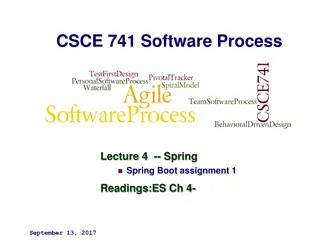
Agenda Keystone I Boot Overview Rom Boot Loader Intermediate Boot Loader TI Information Selective Disclosure 22
Why IBL? Boot from Nand flash on C667x/C6670 Boot from FTP server Boot from images with different format Boot from multiple images Extended functions before boot DSP I2C IBL DSP TI Information Selective Disclosure 23
IBL Support Default device Nand Flash Nor Flash TFTP Image Format ELF BBLOB TI Information Selective Disclosure 24
Easy to Use Compile IBL source code in MCSDK directory Burn IBL and parameter set to I2C EEPROM Generate user image Burn user image to Nand/Nor or upload to FTP server Set boot mode pin on DSP Power on DSP TI Information Selective Disclosure 25
Reference KeyStone Architecture Bootloader User Guide TMS320C667x/0(C665x) Multicore Fixed and Floating-Point Digital Signal Processor Data Manual BIOS-MCSDK User Guide http://processors.wiki.ti.com/index.php/MAD_Utils_User_Guide http://linux-c6x.org/wiki/index.php/IBL_version_1.0.0.11 www.deyisupport.com TI Information Selective Disclosure 26
Backup TI Information Selective Disclosure TI Information Selective Disclosure 27