Introduction to Graphviz: A Powerful Visualization Tool
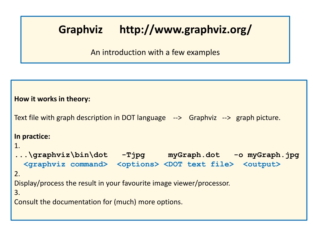
Graphviz is a versatile tool used to create visual representations of graphs by describing them in the DOT language. The process involves writing a text file with the graph description, using Graphviz to generate the graph picture, and then viewing or processing the output. It provides a detailed introduction with examples, showcasing how it automates the layout and position of nodes and edges. Graphviz offers a wide range of options to customize and control the graph layout to suit various needs.
Download Presentation

Please find below an Image/Link to download the presentation.
The content on the website is provided AS IS for your information and personal use only. It may not be sold, licensed, or shared on other websites without obtaining consent from the author. Download presentation by click this link. If you encounter any issues during the download, it is possible that the publisher has removed the file from their server.
E N D
Presentation Transcript
Graphviz http://www.graphviz.org/ An introduction with a few examples How it works in theory: Text file with graph description in DOT language --> Graphviz --> graph picture. In practice: 1. ...\graphviz\bin\dot -Tjpg myGraph.dot -o myGraph.jpg <graphviz command> <options> <DOT text file> <output> 2. Display/process the result in your favourite image viewer/processor. 3. Consult the documentation for (much) more options.
Graphviz http://www.graphviz.org/ Input DOT text file Output graph Example01 { 0 -- 1 0 -- 2 1 -- 3 1 -- 4 2 -- 4 3 -- 4 } The Input code examples should be more or less self-explanatory. For more details see the documentation http://www.graphviz.org/Documentation.php or the web/google in general.
Graphviz http://www.graphviz.org/ Input DOT text file Output // Node names may be arbitrary. // Comments (also /* and */ ) // are not processed. graph Example02 { Zero -- One Zero -- TWO One -- "exactly 3" One -- 4 TWO -- 4 "exactly 3" -- 4 } The nodes and edges layout and position is controlled by Graphviz. It is an automated process with no guarantee that the user will be happy with the result. More advanced option of Graphviz and DOT language allow the user to control graph layout nearly(!) perfectly. Be aware that "nearly" can be sometimes quite far from ideal.
Graphviz http://www.graphviz.org/ Input DOT text file Output // Various edge attributes // can be specified in [] brackets. graph Example03 { 0 -- 1 0 -- 2 [penwidth=3] 1 -- 3 [penwidth=5, color=red] 1 -- 4 [color=green] 2 -- 4 [color="#00A0FF"] // follows //usual RGB scheme 3 -- 4 }
Graphviz Input DOT text file http://www.graphviz.org/ // Nodes might be listed separately // and their attributes might be specified // like those of the edges. Output graph Example04 { 0 [color=blue] 1 [shape=square] 2 [penwidth=5] 3 [color=blue,shape=square,penwidth=5] // unlisted nodes assume default attributes 0 -- 1 0 -- 2 1 -- 3 1 -- 4 2 -- 4 3 -- 4 }
Graphviz Input DOT text file http://www.graphviz.org/ // Default node and edge attributes might be redefined. // Note the keywords 'node' and 'edge'. // All subsequently listed nodes/edges are affected. Output graph Example05 { node [style=filled,fillcolor=yellow,penwidth=3] 0 3 4 node [shape=square] 1 2 // Node 5 and 6 attributes will be // [style=filled,fillcolor=yellow, penwidth=3,shape=square] 0 -- 1 0 -- 2 1 -- 3 edge [penwidth=5,color=brown] 1 -- 4 2 -- 4 edge [color=blue] // penwidth=5 still holds: 3 -- 4 4 -- 5 4 -- 6 }
Graphviz http://www.graphviz.org/ Input DOT text file // Some other useful node atributes: // Smaller node sizes and a different font. Output graph Example06 { node [ shape=oval // try point, circle, house, octagon ... fixedsize=true width=0.40 height=0.30 fontname="Courier-Bold" ] 0 -- 1 0 -- 2 1 -- 3 1 -- 4 2 -- 4 3 -- 4 4 -- "FIVE is 5." // text overflows the shape 4 -- 6 }
Graphviz http://www.graphviz.org/ Input DOT text file // Directed graphs differ from undirected ones // by the keyword "digraph" // and the edge symbol "->". Output digraph Example07 { node [ shape=oval fixedsize=true width=0.40 height=0.30 fontname="Courier-Bold" ] 0 -> 1 0 -> 2 1 -> 3 1 -> 4 2 -> 4 3 -> 4 4 -> 5 4 -> 6 }
Graphviz Input DOT text file http://www.graphviz.org/ // Binary tree. Note the edge labels // and the global graph attributes. Output digraph Example08 { graph [rankdir=LR,bgcolor="#F0F0FF"] // LR ... drawing direction: Left-Right node [shape=oval,fixedsize=true, width=0.40, height=0.30, style=filled] 0 [fillcolor=black,fontcolor=white ] node [fillcolor=white,fontcolor=black ] 1 2 3 4 5 6 node [fillcolor=maroon,fontcolor=white ] 7 8 9 10 11 12 13 14 0 -> 1 [label="Up"] 0 -> 2 [label="Down"] 1 -> 3 [label="Up"] 1 -> 4 [label="Down"] // ... // few lines missing to fit the text to the slide 6 -> 13 [label="Up"] 6 -> 14 [label="Down"] }
Where to go next? Easy intro: http://www.tonyballantyne.com/graphs.html http://www.graphviz.org/pdf/dotguide.pdf Try experimenting online: http://graphs.grevian.org/graph All Details: http://www.graphviz.org/Gallery.php http://www.graphviz.org/Documentation.php http://www.graphviz.org/content/faq Warning Graphviz comes with seven graph picture generating engines based on different strategies and algorithms: Circo, dot, fdp, neato, osage, sfdp, twopi. Often, dot and fdp work best but that also depends on the particular graph. Experimentation and patience are recommended to get the desired result. The pictures in this presentation were produced by different engines.
