Interlocked Collimator DOROS Front-End Exchange
DOROS
1
E
x
c
h
a
n
g
i
n
g
a
n
i
n
t
e
r
l
o
c
k
e
d
c
o
l
l
i
m
a
t
o
r
D
O
R
O
S
f
r
o
n
t
-
e
n
d
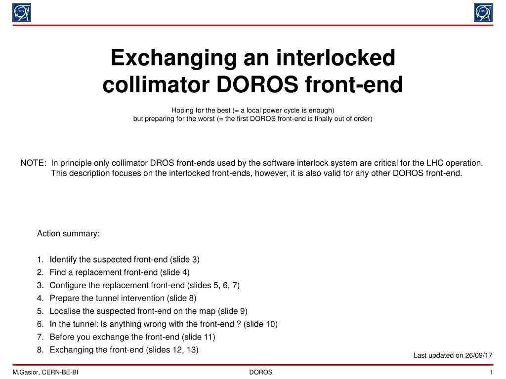
Hoping for the best (= a local power cycle is enough)
but preparing for the worst (= the first DOROS front-end is finally out of order)
Action summary:
1.
Identify the suspected front-end (slide 3)
2.
Find a replacement front-end (slide 4)
3.
Configure the replacement front-end (slides 5, 6, 7)
4.
Prepare the tunnel intervention (slide 8)
5.
Localise the suspected front-end on the map (slide 9)
6.
In the tunnel: Is anything wrong with the front-end ? (slide 10)
7.
Before you exchange the front-end (slide 11)
8.
Exchanging the front-end (slides 12, 13)
Last updated on 26/09/17
NOTE: In principle only collimator DROS front-ends used by the software interlock system are critical for the LHC operation.
This description focuses on the interlocked front-ends, however, it is also valid for any other DOROS front-end.
DOROS
2
(
P
r
i
o
r
i
t
i
s
e
d
)
e
x
p
e
r
t
p
h
o
n
e
l
i
s
t
s
Hardware:
−
Marek: 163104
−
Jakub: 167883
−
Tom: 167012
−
Christian: 164125
−
Michal: 167954
P
l
e
a
s
e
s
t
a
r
t
c
a
l
l
i
n
g
f
r
o
m
t
h
e
t
o
p
o
f
t
h
e
l
i
s
t
.
O
n
l
y
w
h
e
n
t
h
e
p
e
r
s
o
n
d
o
e
s
n
o
t
a
n
s
w
e
r
t
w
i
c
e
,
p
l
e
a
s
e
m
o
v
e
t
o
t
h
e
n
e
x
t
o
n
e
.
Software:
−
Guillaume: 167317
−
Stephen: 164559
Useful phone numbers:
−
CCC
LHC island: 77600, 70478.
Useful links:
−
http://cern.ch/gasior/pro/DOROS
DOROS
3
1
.
I
d
e
n
t
i
f
y
t
h
e
b
a
d
f
r
o
n
t
-
e
n
d
First double check whether the suspected front-end is used by the software interlock system (SIS).
All SIS DOROS front-ends and their corresponding collimators can be found in the SIS DOROS device inventory:
http://cern.ch/gasior/pro/DOROS/docs/DOROS_SIS_device_inventory.pdf
(an example in Appendix 1).
If the suspected front-end is not on the list, then maybe it does not have to be exchanged in an emergency mode.
Contact the CCC to ask how to proceed.
Once it is sure that the suspected front-end is a critical one, this front-end should be precisely identified in order to localise it in
the machine and to prepare in the lab its replacement.
Find in the SIS device inventory the problematic collimator BPM and its corresponding DOROS front-end.
As an example, let’s assume that the problem is with the BPMs of collimator TCTPH.4L1.B1 .
Then in the PDF file one finds its corresponding front-end CFB‐US152‐BIDRC1:
Try pinging the front-end from a machine on the technical network (command “ping CFB‐US152-BIDRC1”).
If the front-end responses, then it is alive and most likely it can be reset remotely and the exchange will not be needed.
Ask a CCC operator to reset the front-end. If this fails, contact Marek (163104) or Jakub (167883) or Guillaume (167317), so
that they attempt resetting the front-end remotely.
If the front-end does not ping, then it should be assumed that it must be replaced. Now it is well identified.
From the device inventory please note the front-end ID (0x11FF), its channel configuration (8 |
00
)
and its rack (BY01.US152). This information will be needed later.
DOROS
4
2
.
F
i
n
d
a
r
e
p
l
a
c
e
m
e
n
t
f
r
o
n
t
-
e
n
d
a
n
d
t
o
o
l
s
Depending how many channels are used in the suspected front-end, you will need one of the two DOROS front-end types:
an 8-channel standard front-end or a 4-channel “half” front-end.
You need a 4-channel “half” front-end only if the channel configuration is (4 |
10
). For all other cases you need an 8-channel
standard front-end. If needed, the 8-channel version can also replace a 4-channel version.
The first number in the channel configuration says how many front-end channels have beam signals connected.
The numbers in
red
give the corresponding channel configuration bits, which need to be set on a configuration DIP switch.
The front-end configuration will be explained later.
Find the replacement front-end. The spare DOROS front-ends are in the “storage room” 866-1-406, in the first rack (BY01),
as on the left photo below. They are all marked with an adhesive label “COLLIMATOR SPARE”, as shown on the right photo
below. The spares are “hot“ ones kept in the operational state. Before you turn the front-end off, please have a look on the
standard look of the front panel LEDs. This may help later in the LHC tunnel. Then turn the front-end off with the power
switch on the rear panel next to the power cord and disconnect: the power cord, the Ethernet, the BST fibres and the test
signal cables, which may be connected to the beam inputs on the back of the front-end.
Then remove the front-end from the rack and take it for configuration.
In the first rack (BY01), near the spare front-ends, there is a bag labelled “DOROS INTERVENTION TOOLBAG” with all
necessary stuff you may need. Take the toolbag as well.
DOROS
5
3
.
1
.
C
o
n
f
i
g
u
r
e
t
h
e
r
e
p
l
a
c
e
m
e
n
t
f
r
o
n
t
-
e
n
d
(
1
/
3
)
Once you have the spare front-end, you need to configure it to the same state as the suspected front-end to be replaced.
For this you need to remove the top lid and localise three 8-bit DIP switches on the FPGA board, as indicated on the photos
below.
The two left switches SW1 “MAC MSB” and SW2 “MAC LSB” program the front-end ID. This ID sets the last 16 bits
of the front-end MAC address. The DOROS system has a dedicated 16-bit MAC address space 08:00:30:F6:xx:xx.
The third right switch SW3 “FPGA SW” programs the front-end channel configuration and the date of the front-end
assembly. You must set only the channel configuration bits.
DOROS
6
3
.
2
.
C
o
n
f
i
g
u
r
e
t
h
e
r
e
p
l
a
c
e
m
e
n
t
f
r
o
n
t
-
e
n
d
(
2
/
3
)
Program the ID and at the same time the MAC address of the front-end to be installed.
The ID is the same as the ID of the suspected front-end to be replaced.
The switches can be programed with the small screwdriver (size 00) from the DOROS toolbag.
Set the two switches SW1 “MAC MSB” and SW2 “MAC LSB” with the front-end ID.
For example, the hexadecimal ID 18FF in binary is 0001
1000
1111
1111.
The left photo below shows this configuration programmed.
As a second example, the right photo below shows the switches programmed to 1001
1111
0000
0011 in binary,
which is 9F03 in hexadecimal.
binary 0001 1000 1111 1111 = hex 18FF
binary 1001 1111 0000 0011 = hex 9F03
DOROS
7
3
.
3
.
C
o
n
f
i
g
u
r
e
t
h
e
r
e
p
l
a
c
e
m
e
n
t
f
r
o
n
t
-
e
n
d
(
3
/
3
)
Program the channel configuration bits on SW3 “FPGA SW”.
It is the two most left bits on the switch with the numbers 1 and 2 on the case, as shown on the photo below..
The bits are given in red in the inventory file (“
CH config
” column). They are as follows:
•
00 for the standard 8-channel front-end;
•
10 for the “half” 4-channel front-end;
The remaining bits you leave as they are.
More details on programming SW3 are in Appendix
DOROS
8
4
.
P
r
e
p
a
r
e
t
h
e
t
u
n
n
e
l
i
n
t
e
r
v
e
n
t
i
o
n
All necessary tools, screws and spares are in the DOROS intervention toolbag.
The toolbag contains all you may need during the intervention, so take it with you. The toolbag contains:
•
SMA torque wrench for the SMA beam signal cables and cutting pliers to deal with plastic binders in the tunnel;
•
a small flat-head screwdriver (size 00) to program the DIP switches and work with the front panel M2 screws;
•
a larger flat-head screwdriver (size 2) to work with the M3 screws of the front-end top lid;
•
a larger Philips screwdriver to work with the M5 screws fixing the DOROS front-ends to the racks;
•
slotted countersunk M3x6 screws for fixing the front-end top lid;
•
M2x5 screws with larger heads for fixing the front panel labels (if time permits);
•
a simple 230 V indicator;
•
useful spares: an Ethernet SFP module, 10 A delayed fuses, a power cord, a few Ethernet cables;
•
a ball-pen, a permanent marker, a small notebook, cable binders.
Once the front-end switches are programed, close the top lid of the front-end and fix it with at least
6 countersunk M3x6 screws: 4 in each corner and two on the bar separating the power supply compartment.
The front-end is equipped with one Ethernet and two BST SFP modules.
The SFPs are fragile, so pay attention that they do not hit anything during the transport.
Before you drive to the LHC you may consult the photo of the rack with the suspected front-end.
This can help in identifying the rack in the LHC tunnel.
Photos of all DOROS collimator racks can be found here:
http://cern.ch/gasior/pro/DOROS/pict_c
Make sure that in your phone contacts you have the LHC CCC numbers 77600, 70478.
Do not forget about the standard items you must have in the LHC tunnel:
•
your access card, your personal dosimeter and your mobile phone;
•
an electronic dosimeter;
•
safety shoes;
•
a helmet with a front lamp.
DOROS
9
5
.
L
o
c
a
l
i
s
e
t
h
e
s
u
s
p
e
c
t
e
d
f
r
o
n
t
-
e
n
d
o
n
t
h
e
m
a
p
Go to the Racks section of the CERN Geographic Information System:
https://gisrec.cern.ch/gisportal/racks.htm
In the search window on the top of the page type the name of the front-end and the system will show you its rack.
For example, if you type “cfb-us152-bidrc1”, you will see after a bit of zooming in a map like this with the front-end rack
indicated by the small circle:
DOROS
10
6
.
I
n
t
h
e
t
u
n
n
e
l
:
I
s
a
n
y
t
h
i
n
g
w
r
o
n
g
w
i
t
h
t
h
e
f
r
o
n
t
-
e
n
d
?
Once you get to the rack with the bad front-end, double check that this is the front-end you should be dealing with.
Each front-end has a label with the front-end ID, its network name and the names of the collimators. Examples are shown
below.
It could be that the front-end data is not received by the FESA server but the front-end works just fine.
This can happen if there is a problem with the Ethernet connection after the first Ethernet switch to which
the front-end is directly connected. In this case the front-end operates correctly but the data is lost on the way.
This is a consequence of the fact that the data is send as UDPs.
The proper operation of the front-end is indicated by the following states of the front panel LEDs:
•
all 4 red power LEDs are lit with an equal brightness;
•
out of 8 status LEDs at least 4 or 5 are flashing in green at a 1 Hz rate:
the 4 lower ones with numbers 3, 4, 7, 8 and sometimes also LED number 2.
More details on the front panel LEDs are given in Appendix 2 (slides 14, 15 and 16).
If you see that the front-end LEDs are in the above “everything OK” state, then check again that this is indeed
the problematic front-end whose data is not received.
If this is the right front-end, make a power cycle.
After maximally 30 seconds the front-end should return to the normal operation indicated by the LEDs.
Then ask the CCC or one of the system experts to check whether the front-end data is now being received.
If at this point the LEDs still indicate the proper operation and the data is not received by the FESA server,
please ask the CCC to contact the Network Service so that they diagnose the connection to the front-end.
The front-end can be localised in the network by its unique name.
DOROS
11
7
.
B
e
f
o
r
e
y
o
u
e
x
c
h
a
n
g
e
t
h
e
f
r
o
n
t
-
e
n
d
First make sure that the front-end does not lack 230 V.
Most likely this is the case if all 12 front panel LEDs are permanently off.
Then please check:
•
presence of 230 V in the socket from which the front-end is powered (you can use the indicator from the toolbag);
•
differential circuit breaker of the socket to which the front-end is connected;
•
the front-end fuse (one spare 10 A delayed fuse is inside the fuse drawer, more you have in the toolbag).
If some LEDs are on, please document the fault by taking a photo of the front panel.
Make a power cycle of the front-end.
If the LEDs indicate that the front-end started correctly (as explained on the previous slide),
then ask the CCC or one of the system experts to check whether the front-end started sending data.
If it looks as the front-end still does not work properly, please make a second power-cycle.
DOROS front-ends have two redundant program memories used alternately upon each powering up,
so it could be that the front-end starts correctly on the second attempt.
If you see that all 4 power LEDs are on with equal brightness and only some status LEDs are on, it could be that
the Ethernet SFP module is out of order. Then you should exchange it with a spare module from the toolbag.
It makes sense to exchange the Ethernet SFP when the status LEDs are in one of the following states:
•
LED 1 lit in red and flashing at 1 Hz (= SFP module not seen by the front-end);
•
status LEDs 1 and 2 lit in green and LED 3 flashing in red at 1 Hz (= no Ethernet link).
DOROS
12
8
.
1
.
E
x
c
h
a
n
g
i
n
g
t
h
e
f
r
o
n
t
-
e
n
d
(
1
/
2
)
Before you start exchanging the front-end, please make photos of the installation from the front and from the back.
Such photos may help to verify that the installation is the same after the intervention.
Do not rush to remove the old front-end. Go step by step, as explained below.
First check whether the new front-end gets the Ethernet correctly. This should be done before installing the front-end
in the rack, just in case that the Ethernet does not work and the front-end must be opened to verify
the DIP switches with the front-end ID.
•
If there is some room above the old front-end you may consider putting the new front-end for the testing just
on top of the old one. If there is no room, put the new front-end on the floor.
•
Power the new front-end. You may use the spare power cord from the toolbag.
•
Connect the Ethernet cable. If necessary, the Ethernet cable you could extend with spares from the toolbag.
•
Check the front-panel LEDs. After maximally 30 seconds they should indicate the proper operation,
as explained on slide 9 and in Appendix 2 on slide 15.
If the front-end gest the Ethernet correctly, then start the front-end exchange, as described on the next page.
If the Ethernet does not work, please make first a power cycle.
If the Ethernet still does not work, then turn the front-end off. Unplug the power cord and open the front-end
to verify the DIP switches with the front-end ID.
The ID which should be programmed is also written on the front panel label of the “old” front-end.
If the ID is correctly programmed, please anyway move each bit back and forth and make sure that each switch
reaches the extreme position. Then close the top lid, power the front-end and check the front panel LEDs.
If the Ethernet still does not work, please ask the CCC to contact the Network Service so that they diagnose
the front-end Ethernet connection.
DOROS
13
8
.
2
.
E
x
c
h
a
n
g
i
n
g
t
h
e
f
r
o
n
t
-
e
n
d
(
2
/
2
)
Once you know that the new front-end gets Ethernet properly, you can start the exchange.
At this point make sure you have made photos of the installation from the front and from the back.
Disconnect the Ethernet cable and the SFP fibre. Remember how the fibre was connected.
Make sure that the front-end is turned off and disconnect the power cord.
Unscrew the SMA beam signal cables using the torque wrench from the toolbag.
The cables are labelled with the front-end channel numbers.
Please remember how the cables are arranged and try to put them in a similar way for the new front-end.
Remove the old front-end from the rack.
Put the new front-end into the rack.
First connect it to 230 V, plug the Ethernet cable and check whether the front-end works.
Continue with the installation only if the front-end gets Ethernet correctly.
Plug the timing SFP as it was on the old front-end and connect the BST fibre.
Connect the SMA beam signal cables.
First you screw the SMA connectors with fingers, paying attention on the cable labels and the front-end input numbers.
When all SMA cables are fixed with fingers and the cables are arranged properly, fix the SMA cables
using the torque wrench.
If you have time, unscrew the front-end label from the old front-end and put it on the new one.
Take photos of the installation from the front and from the back.
Before you leave the tunnel call the CCC or one of the system experts to make sure that the new front-end
sends the data correctly.
DOROS
14
A
p
p
e
n
d
i
x
1
.
I
n
v
e
n
t
o
r
y
o
f
t
h
e
S
I
S
c
o
l
l
i
m
a
t
o
r
f
r
o
n
t
-
e
n
d
s
N
O
T
E
:
T
h
i
s
l
i
s
t
i
s
a
n
e
x
a
m
p
l
e
o
n
l
y
.
T
h
e
m
o
s
t
r
e
c
e
n
t
l
i
s
t
i
s
u
n
d
e
r
t
h
e
l
i
n
k
:
h
t
t
p
:
/
/
c
e
r
n
.
c
h
/
g
a
s
i
o
r
/
p
r
o
/
D
O
R
O
S
/
d
o
c
s
/
D
O
R
O
S
_
S
I
S
_
d
e
v
i
c
e
_
i
n
v
e
n
t
o
r
y
.
p
d
f
DOROS
15
A
p
p
e
n
d
i
x
2
.
D
O
R
O
S
f
r
o
n
t
p
a
n
e
l
L
E
D
s
(
1
/
3
–
p
o
w
e
r
)
There are two generations of DOROS front-ends with different naming for the front panel LEDs, see the drawings below.
However, in both versions the LED numbering is the same, so in this description the LEDs will be referred only by the group
name “power” or “status” and the numbers.
During normal operation all four power LEDs should be lit with similar brightness.
If one of the LEDs is off or its brightness is different then:
•
the corresponding power supply is not working properly;
•
the circuitry powered from the corresponding power supply is not working properly.
The LEDs signalise operation of the main power supplies as follows:
•
LED 1: +12 V analogue;
•
LED 2: -12 V analogue;
•
LED 3: +5 V analogue;
•
LED 4: +5 V digital.
p
o
w
e
r
L
E
D
s
s
t
a
t
u
s
L
E
D
s
DOROS
16
A
p
p
e
n
d
i
x
2
.
D
O
R
O
S
f
r
o
n
t
p
a
n
e
l
L
E
D
s
(
2
/
3
–
o
p
e
r
a
t
i
o
n
)
During normal operation the status LEDs are as presented on the right.
The two top LEDs correspond to optical timing signals, which are not essential
for fundamental operation of the front-end. They are explained on the next slide.
The two shown cases correspond to normal operation with the front-end
booted up from program memory 1 or program memory 2.
Any other LED combination does not correspond to a normal front-end operation.
Two important states of the start-up sequence are shown on the right.
The first LED combination signalises that the front-end waits for the Ethernet link.
The situation shown on the right, with just LED 1 flashing, means that the
front-end does not have a good Ethernet SFP module.
Legend:
shining green, shining red
flashing green, flashing red
off
don’t care
memory 1 memory 2
no link no SFP
DOROS
17
A
p
p
e
n
d
i
x
2
.
D
O
R
O
S
f
r
o
n
t
p
a
n
e
l
L
E
D
s
(
3
/
3
–
t
i
m
i
n
g
)
The top two LEDs 1 and 5 indicate the BST timing status for beam 1 (left SFP) and beam 2 (right SFP), respectively.
All collimator front-ends receive only one timing, B1 or B2, depending which beam signals are processed.
Please note that DOROS font-ends can measure beam without the BST timing.
Also the post-mortem triggers are received over the Ethernet link.
Each LED can indicate one of the following states:
shining green: the timing being received;
flashing green/red: receiving the timing of the other beam;
flashing green: the SFP module not present;
shining red: the SFP module present but no timing signal being received.
DOROS
18
A
p
p
e
n
d
i
x
3
.
P
r
o
g
r
a
m
m
i
n
g
S
W
3
“
F
P
G
A
S
W
”
D
I
P
s
w
i
t
c
h
T
h
e
2
m
o
s
t
l
e
f
t
b
i
t
s
o
f
D
I
P
s
w
i
t
c
h
S
W
3
“
F
P
G
A
S
W
”
p
r
o
g
r
a
m
t
h
e
c
h
a
n
n
e
l
c
o
n
f
i
g
u
r
a
t
i
o
n
o
f
t
h
e
f
r
o
n
t
-
e
n
d
.
T
h
e
c
h
a
n
n
e
l
c
o
n
f
i
g
u
r
a
t
i
o
n
b
i
t
s
a
r
e
l
a
b
e
l
l
e
d
w
i
t
h
t
h
e
n
u
m
b
e
r
s
1
a
n
d
2
o
n
t
h
e
s
w
i
t
c
h
c
a
s
e
a
s
s
e
e
n
o
n
t
h
e
p
h
o
t
o
b
e
l
o
w
.
T
h
e
b
i
t
s
a
r
e
m
a
r
k
e
d
“
C
C
”
o
n
t
h
e
p
h
o
t
o
.
The channel configuration bits should be:
•
00 for the standard 8-channel front-end;
•
10 for the “half” 4-channel front-end;
•
01 for the standard 8-channel front-end with 6 channels active;
for the time being there is only one such a case, namely CFB‐RR77‐BIDRC1.
The 6 right bits of the DIP switch program the date of the front-end installation.
The bits are labelled 3 .. 8 on the switch case as seen on the photo below.
B
i
t
s
3
,
4
,
5
,
6
,
m
a
r
k
e
d
“
Y
E
A
R
”
o
n
t
h
e
p
h
o
t
o
b
e
l
o
w
,
s
e
t
t
h
e
c
a
l
e
n
d
a
r
y
e
a
r
m
o
d
u
l
o
1
6
.
S
o
t
h
a
t
:
2
0
1
7
=
0
0
0
1
,
2
0
1
8
=
0
0
1
0
,
2
0
1
9
=
0
0
1
1
,
2
0
2
0
=
0
1
0
0
,
2
0
2
1
=
0
1
0
1
,
2
0
2
2
=
0
1
1
0
,
2
0
2
3
=
0
1
1
1
a
n
d
s
o
o
n
.
B
i
t
s
7
a
n
d
8
,
m
a
r
k
e
d
“
Q
”
o
n
t
h
e
p
h
o
t
o
b
e
l
o
w
m
a
r
k
t
h
e
q
u
a
r
t
e
r
o
f
t
h
e
y
e
a
r
m
i
n
u
s
o
n
e
:
0
0
=
1
s
t
q
u
a
r
t
e
r
,
0
1
=
2
n
d
q
u
a
r
t
e
r
,
1
0
=
3
r
d
q
u
a
r
t
e
r
,
1
1
=
4
t
h
q
u
a
r
t
e
r
.
On the photo below the channel configuration bits are 00, indicating the standard 8-channel front-end.
The date bits are 0001
10 indicating year 2017 (or 2033, or 2049, …) and the 3
rd
quarter.
DOROS
19
A
p
p
e
n
d
i
x
4
.
B
o
u
n
d
a
r
y
c
o
n
d
i
t
i
o
n
s
Some collimator BPM DOROS front-ends provide orbit readings for the Software Interlock System (SIS).
Then the SIS protects the LHC machine from excessive beam offsets in collimators with embedded BPMs.
LHC beams are dumped if one of the SIS DOROS front-ends stops sending data for more than 60 seconds.
LHC beams cannot be injected if one of the SIS DOROS front-ends does not send data.
A SIS DOROS front-end which does not send data must be replaced.
An estimate for the DOROS front-end failure rate is currently less than one per year for the 6 SIS front-ends.
Before the software interlocks have been introduced in September 2017 the reliability of the collimator DOROS front-ends
had been monitored for months without any detected failure.
The reliability of the DOROS front-ends depends a lot on the reliability of the firmware of their FPGAs along with the
efficiency of the exception detection and handling. This firmware is being improved using the operational experience gained
during the system operation.
The DOROS front-ends are tolerant for single even upsets. If such an event is detected then the front-end is restarted,
returning to regular operation within a few seconds. This short break in data transmission is tolerated by the interlock
system. The same mechanism is used to recover from radiation-induced latch-ups of the system integrated circuits.
During the YETS 2017 it will be attempted to introduce redundancy for the SIS DOROS front-ends.
Signals from the upstream and downstream collimator BPMs would be processed by different DOROS front-ends.
As signals form one BPM are sufficient for the SIS to operate, then a failure of one of the two DOROS front-ends processing
the downstream and upstream signals can be tolerated.
Action items for exchanging an interlocked collimator DOROS front-end in the LHC operation, including identifying, finding a replacement, configuring, preparing for exchange, and localizing on a map.

Download Presentation

Please find below an Image/Link to download the presentation.
The content on the website is provided AS IS for your information and personal use only. It may not be sold, licensed, or shared on other websites without obtaining consent from the author.If you encounter any issues during the download, it is possible that the publisher has removed the file from their server.
You are allowed to download the files provided on this website for personal or commercial use, subject to the condition that they are used lawfully. All files are the property of their respective owners.
The content on the website is provided AS IS for your information and personal use only. It may not be sold, licensed, or shared on other websites without obtaining consent from the author.
E N D
Presentation Transcript
Exchanging an interlocked collimator DOROS front-end Hoping for the best (= a local power cycle is enough) but preparing for the worst (= the first DOROS front-end is finally out of order) NOTE: In principle only collimator DROS front-ends used by the software interlock system are critical for the LHC operation. This description focuses on the interlocked front-ends, however, it is also valid for any other DOROS front-end. Action summary: 1. Identify the suspected front-end (slide 3) 2. Find a replacement front-end (slide 4) 3. Configure the replacement front-end (slides 5, 6, 7) 4. Prepare the tunnel intervention (slide 8) 5. Localise the suspected front-end on the map (slide 9) 6. In the tunnel: Is anything wrong with the front-end ? (slide 10) 7. Before you exchange the front-end (slide 11) 8. Exchanging the front-end (slides 12, 13) Last updated on 26/09/17 M.Gasior, CERN-BE-BI DOROS 1
(Prioritised) expert phone lists Please start calling from the top of the list. Only when the person does not answer twice, please move to the next one. Hardware: Software: Marek: 163104 Jakub: 167883 Tom: 167012 Christian: 164125 Michal: 167954 Guillaume: 167317 Stephen: 164559 Useful phone numbers: CCC LHC island: 77600, 70478. Useful links: http://cern.ch/gasior/pro/DOROS M.Gasior, CERN-BE-BI DOROS 2
1. Identify the bad front-end First double check whether the suspected front-end is used by the software interlock system (SIS). All SIS DOROS front-ends and their corresponding collimators can be found in the SIS DOROS device inventory: http://cern.ch/gasior/pro/DOROS/docs/DOROS_SIS_device_inventory.pdf (an example in Appendix 1). If the suspected front-end is not on the list, then maybe it does not have to be exchanged in an emergency mode. Contact the CCC to ask how to proceed. Once it is sure that the suspected front-end is a critical one, this front-end should be precisely identified in order to localise it in the machine and to prepare in the lab its replacement. Find in the SIS device inventory the problematic collimator BPM and its corresponding DOROS front-end. As an example, let s assume that the problem is with the BPMs of collimator TCTPH.4L1.B1 . Then in the PDF file one finds its corresponding front-end CFB US152 BIDRC1: point collimator front-end ID CH config rack collimator 1 and 2 SIS DEV 1U+D, 2U+D expoert log. P1 L TCTP H + V B1 CFB-US152-BIDRC1 0x11FF 8 | 00 BY01.US152 TCTPH.4L1.B1 TCTPV.4L1.B1 y y *H.A4L1.B1 *V.A4L1.B1 4L_H_B1 4L_V_B1 Try pinging the front-end from a machine on the technical network (command ping CFB US152-BIDRC1 ). If the front-end responses, then it is alive and most likely it can be reset remotely and the exchange will not be needed. Ask a CCC operator to reset the front-end. If this fails, contact Marek (163104) or Jakub (167883) or Guillaume (167317), so that they attempt resetting the front-end remotely. If the front-end does not ping, then it should be assumed that it must be replaced. Now it is well identified. From the device inventory please note the front-end ID (0x11FF), its channel configuration (8 | 00) and its rack (BY01.US152). This information will be needed later. M.Gasior, CERN-BE-BI DOROS 3
2. Find a replacement front-end and tools Depending how many channels are used in the suspected front-end, you will need one of the two DOROS front-end types: an 8-channel standard front-end or a 4-channel half front-end. You need a 4-channel half front-end only if the channel configuration is (4 | 10). For all other cases you need an 8-channel standard front-end. If needed, the 8-channel version can also replace a 4-channel version. The first number in the channel configuration says how many front-end channels have beam signals connected. The numbers in red give the corresponding channel configuration bits, which need to be set on a configuration DIP switch. The front-end configuration will be explained later. Find the replacement front-end. The spare DOROS front-ends are in the storage room 866-1-406, in the first rack (BY01), as on the left photo below. They are all marked with an adhesive label COLLIMATOR SPARE , as shown on the right photo below. The spares are hot ones kept in the operational state. Before you turn the front-end off, please have a look on the standard look of the front panel LEDs. This may help later in the LHC tunnel. Then turn the front-end off with the power switch on the rear panel next to the power cord and disconnect: the power cord, the Ethernet, the BST fibres and the test signal cables, which may be connected to the beam inputs on the back of the front-end. Then remove the front-end from the rack and take it for configuration. In the first rack (BY01), near the spare front-ends, there is a bag labelled DOROS INTERVENTION TOOLBAG with all necessary stuff you may need. Take the toolbag as well. M.Gasior, CERN-BE-BI DOROS 4
3.1. Configure the replacement front-end (1/3) Once you have the spare front-end, you need to configure it to the same state as the suspected front-end to be replaced. For this you need to remove the top lid and localise three 8-bit DIP switches on the FPGA board, as indicated on the photos below. The two left switches SW1 MAC MSB and SW2 MAC LSB program the front-end ID. This ID sets the last 16 bits of the front-end MAC address. The DOROS system has a dedicated 16-bit MAC address space 08:00:30:F6:xx:xx. The third right switch SW3 FPGA SW programs the front-end channel configuration and the date of the front-end assembly. You must set only the channel configuration bits. M.Gasior, CERN-BE-BI DOROS 5
3.2. Configure the replacement front-end (2/3) Program the ID and at the same time the MAC address of the front-end to be installed. The ID is the same as the ID of the suspected front-end to be replaced. The switches can be programed with the small screwdriver (size 00) from the DOROS toolbag. Set the two switches SW1 MAC MSB and SW2 MAC LSB with the front-end ID. For example, the hexadecimal ID 18FF in binary is 0001100011111111. The left photo below shows this configuration programmed. As a second example, the right photo below shows the switches programmed to 1001 111100000011 in binary, which is 9F03 in hexadecimal. binary 1001 1111 0000 0011 = hex 9F03 binary 0001 1000 1111 1111 = hex 18FF M.Gasior, CERN-BE-BI DOROS 6
3.3. Configure the replacement front-end (3/3) Program the channel configuration bits on SW3 FPGA SW . It is the two most left bits on the switch with the numbers 1 and 2 on the case, as shown on the photo below.. The bits are given in red in the inventory file ( CH config column). They are as follows: 00 for the standard 8-channel front-end; 10 for the half 4-channel front-end; The remaining bits you leave as they are. More details on programming SW3 are in Appendix M.Gasior, CERN-BE-BI DOROS 7
4. Prepare the tunnel intervention All necessary tools, screws and spares are in the DOROS intervention toolbag. The toolbag contains all you may need during the intervention, so take it with you. The toolbag contains: SMA torque wrench for the SMA beam signal cables and cutting pliers to deal with plastic binders in the tunnel; a small flat-head screwdriver (size 00) to program the DIP switches and work with the front panel M2 screws; a larger flat-head screwdriver (size 2) to work with the M3 screws of the front-end top lid; a larger Philips screwdriver to work with the M5 screws fixing the DOROS front-ends to the racks; slotted countersunk M3x6 screws for fixing the front-end top lid; M2x5 screws with larger heads for fixing the front panel labels (if time permits); a simple 230 V indicator; useful spares: an Ethernet SFP module, 10 A delayed fuses, a power cord, a few Ethernet cables; a ball-pen, a permanent marker, a small notebook, cable binders. Once the front-end switches are programed, close the top lid of the front-end and fix it with at least 6 countersunk M3x6 screws: 4 in each corner and two on the bar separating the power supply compartment. The front-end is equipped with one Ethernet and two BST SFP modules. The SFPs are fragile, so pay attention that they do not hit anything during the transport. Before you drive to the LHC you may consult the photo of the rack with the suspected front-end. This can help in identifying the rack in the LHC tunnel. Photos of all DOROS collimator racks can be found here: http://cern.ch/gasior/pro/DOROS/pict_c Make sure that in your phone contacts you have the LHC CCC numbers 77600, 70478. Do not forget about the standard items you must have in the LHC tunnel: your access card, your personal dosimeter and your mobile phone; an electronic dosimeter; safety shoes; a helmet with a front lamp. M.Gasior, CERN-BE-BI DOROS 8
5. Localise the suspected front-end on the map Go to the Racks section of the CERN Geographic Information System: https://gisrec.cern.ch/gisportal/racks.htm In the search window on the top of the page type the name of the front-end and the system will show you its rack. For example, if you type cfb-us152-bidrc1 , you will see after a bit of zooming in a map like this with the front-end rack indicated by the small circle: M.Gasior, CERN-BE-BI DOROS 9
6. In the tunnel: Is anything wrong with the front-end ? Once you get to the rack with the bad front-end, double check that this is the front-end you should be dealing with. Each front-end has a label with the front-end ID, its network name and the names of the collimators. Examples are shown below. It could be that the front-end data is not received by the FESA server but the front-end works just fine. This can happen if there is a problem with the Ethernet connection after the first Ethernet switch to which the front-end is directly connected. In this case the front-end operates correctly but the data is lost on the way. This is a consequence of the fact that the data is send as UDPs. The proper operation of the front-end is indicated by the following states of the front panel LEDs: all 4 red power LEDs are lit with an equal brightness; out of 8 status LEDs at least 4 or 5 are flashing in green at a 1 Hz rate: the 4 lower ones with numbers 3, 4, 7, 8 and sometimes also LED number 2. More details on the front panel LEDs are given in Appendix 2 (slides 14, 15 and 16). If you see that the front-end LEDs are in the above everything OK state, then check again that this is indeed the problematic front-end whose data is not received. If this is the right front-end, make a power cycle. After maximally 30 seconds the front-end should return to the normal operation indicated by the LEDs. Then ask the CCC or one of the system experts to check whether the front-end data is now being received. If at this point the LEDs still indicate the proper operation and the data is not received by the FESA server, please ask the CCC to contact the Network Service so that they diagnose the connection to the front-end. The front-end can be localised in the network by its unique name. M.Gasior, CERN-BE-BI DOROS 10
7. Before you exchange the front-end First make sure that the front-end does not lack 230 V. Most likely this is the case if all 12 front panel LEDs are permanently off. Then please check: presence of 230 V in the socket from which the front-end is powered (you can use the indicator from the toolbag); differential circuit breaker of the socket to which the front-end is connected; the front-end fuse (one spare 10 A delayed fuse is inside the fuse drawer, more you have in the toolbag). If some LEDs are on, please document the fault by taking a photo of the front panel. Make a power cycle of the front-end. If the LEDs indicate that the front-end started correctly (as explained on the previous slide), then ask the CCC or one of the system experts to check whether the front-end started sending data. If it looks as the front-end still does not work properly, please make a second power-cycle. DOROS front-ends have two redundant program memories used alternately upon each powering up, so it could be that the front-end starts correctly on the second attempt. If you see that all 4 power LEDs are on with equal brightness and only some status LEDs are on, it could be that the Ethernet SFP module is out of order. Then you should exchange it with a spare module from the toolbag. It makes sense to exchange the Ethernet SFP when the status LEDs are in one of the following states: LED 1 lit in red and flashing at 1 Hz (= SFP module not seen by the front-end); status LEDs 1 and 2 lit in green and LED 3 flashing in red at 1 Hz (= no Ethernet link). M.Gasior, CERN-BE-BI DOROS 11
8.1. Exchanging the front-end (1/2) Before you start exchanging the front-end, please make photos of the installation from the front and from the back. Such photos may help to verify that the installation is the same after the intervention. Do not rush to remove the old front-end. Go step by step, as explained below. First check whether the new front-end gets the Ethernet correctly. This should be done before installing the front-end in the rack, just in case that the Ethernet does not work and the front-end must be opened to verify the DIP switches with the front-end ID. If there is some room above the old front-end you may consider putting the new front-end for the testing just on top of the old one. If there is no room, put the new front-end on the floor. Power the new front-end. You may use the spare power cord from the toolbag. Connect the Ethernet cable. If necessary, the Ethernet cable you could extend with spares from the toolbag. Check the front-panel LEDs. After maximally 30 seconds they should indicate the proper operation, as explained on slide 9 and in Appendix 2 on slide 15. If the front-end gest the Ethernet correctly, then start the front-end exchange, as described on the next page. If the Ethernet does not work, please make first a power cycle. If the Ethernet still does not work, then turn the front-end off. Unplug the power cord and open the front-end to verify the DIP switches with the front-end ID. The ID which should be programmed is also written on the front panel label of the old front-end. If the ID is correctly programmed, please anyway move each bit back and forth and make sure that each switch reaches the extreme position. Then close the top lid, power the front-end and check the front panel LEDs. If the Ethernet still does not work, please ask the CCC to contact the Network Service so that they diagnose the front-end Ethernet connection. M.Gasior, CERN-BE-BI DOROS 12
8.2. Exchanging the front-end (2/2) Once you know that the new front-end gets Ethernet properly, you can start the exchange. At this point make sure you have made photos of the installation from the front and from the back. Disconnect the Ethernet cable and the SFP fibre. Remember how the fibre was connected. Make sure that the front-end is turned off and disconnect the power cord. Unscrew the SMA beam signal cables using the torque wrench from the toolbag. The cables are labelled with the front-end channel numbers. Please remember how the cables are arranged and try to put them in a similar way for the new front-end. Remove the old front-end from the rack. Put the new front-end into the rack. First connect it to 230 V, plug the Ethernet cable and check whether the front-end works. Continue with the installation only if the front-end gets Ethernet correctly. Plug the timing SFP as it was on the old front-end and connect the BST fibre. Connect the SMA beam signal cables. First you screw the SMA connectors with fingers, paying attention on the cable labels and the front-end input numbers. When all SMA cables are fixed with fingers and the cables are arranged properly, fix the SMA cables using the torque wrench. If you have time, unscrew the front-end label from the old front-end and put it on the new one. Take photos of the installation from the front and from the back. Before you leave the tunnel call the CCC or one of the system experts to make sure that the new front-end sends the data correctly. M.Gasior, CERN-BE-BI DOROS 13
Appendix 1. Inventory of the SIS collimator front-ends DOROS device inventory M. Gasior, BE-BI-QP v. 26/09/17 logging database path: LHC -> Collimators -> BPM -> DOROS Front-Ends -> P*-> prefix: "LHC.BPT" system C - SIS devices (interlocked) * = U(pstream) D(ownstream) for expert logging "U" device used active ch. CH config point collimator front-end ID rack collimator 1 and 2 SIS DEV 1U+D, 2U+D expoert log. comments P1 L TCTP H + V B1 CFB-US152-BIDRC1 0x11FF 8 | 00 BY01.US152 TCTPH.4L1.B1 TCTPV.4L1.B1 y y *H.A4L1.B1 *V.A4L1.B1 4L_H_B1 4L_V_B1 P1 R TCTP H + V B2 CFB-US152-BIDRC2 0x1101 8 | 00 BY01.US152 TCTPH.4R1.B2 TCTPV.4R1.B2 y y *H.A4R1.B2 *V.A4R1.B2 4R_H_B2 4R_V_B2 P5 L TCTP H + V B1 CFB-USC55-BIDRC1 0x15FF 8 | 00 BY04.USC55 TCTPH.4L5.B1 TCTPV.4L5.B1 y y *H.A4L5.B1 *V.A4L5.B1 4L_H_B1 4L_V_B1 P5 R TCTP H + V B2 CFB-USC55-BIDRC2 0x1501 8 | 00 BY04.USC55 TCTPH.4R5.B2 TCTPV.4R5.B2 y y *H.A4R5.B2 *V.A4R5.B2 ` *H.A4L6.B2 --- 4R_H_B2 4R_V_B2 P6 L TCSP H B2 CFB-UA63-BIDRC1 0x16FF 4 | 10 BY02.UA63 TCSP.A4L6.B2 --- y 4L_H_B2 --- 4-channel front-end P6 R TCSP H B1 CFB-UA67-BIDRC1 0x1601 4 | 10 BY02.UA67 TCSP.A4R6.B1 --- y *H.A4R6.B1 --- 4R_H_B1 --- 4-channel front-end NOTE: This list is an example only. The most recent list is under the link: http://cern.ch/gasior/pro/DOROS/docs/DOROS_SIS_device_inventory.pdf M.Gasior, CERN-BE-BI DOROS 14
Appendix 2. DOROS front panel LEDs (1/3 power) There are two generations of DOROS front-ends with different naming for the front panel LEDs, see the drawings below. However, in both versions the LED numbering is the same, so in this description the LEDs will be referred only by the group name power or status and the numbers. During normal operation all four power LEDs should be lit with similar brightness. If one of the LEDs is off or its brightness is different then: the corresponding power supply is not working properly; the circuitry powered from the corresponding power supply is not working properly. The LEDs signalise operation of the main power supplies as follows: LED 1: +12 V analogue; LED 2: -12 V analogue; LED 3: +5 V analogue; LED 4: +5 V digital. power LEDs status LEDs M.Gasior, CERN-BE-BI DOROS 15
Appendix 2. DOROS front panel LEDs (2/3 operation) 1 2 3 4 5 6 7 8 1 2 3 4 5 6 7 8 During normal operation the status LEDs are as presented on the right. The two top LEDs correspond to optical timing signals, which are not essential for fundamental operation of the front-end. They are explained on the next slide. The two shown cases correspond to normal operation with the front-end booted up from program memory 1 or program memory 2. Any other LED combination does not correspond to a normal front-end operation. memory 1 memory 2 1 2 3 4 5 6 7 8 1 2 3 4 5 6 7 8 Two important states of the start-up sequence are shown on the right. The first LED combination signalises that the front-end waits for the Ethernet link. The situation shown on the right, with just LED 1 flashing, means that the front-end does not have a good Ethernet SFP module. no link no SFP Legend: shining green, shining red flashing green, flashing red off don t care M.Gasior, CERN-BE-BI DOROS 16
Appendix 2. DOROS front panel LEDs (3/3 timing) The top two LEDs 1 and 5 indicate the BST timing status for beam 1 (left SFP) and beam 2 (right SFP), respectively. All collimator front-ends receive only one timing, B1 or B2, depending which beam signals are processed. Please note that DOROS font-ends can measure beam without the BST timing. Also the post-mortem triggers are received over the Ethernet link. Each LED can indicate one of the following states: shining green: the timing being received; flashing green/red: receiving the timing of the other beam; flashing green: the SFP module not present; shining red: the SFP module present but no timing signal being received. M.Gasior, CERN-BE-BI DOROS 17
Appendix 3. Programming SW3 FPGA SW DIP switch The 2 most left bits of DIP switch SW3 FPGA SW program the channel configuration of the front-end. The channel configuration bits are labelled with the numbers 1 and 2 on the switch case as seen on the photo below. The bits are marked CC on the photo. The channel configuration bits should be: 00 for the standard 8-channel front-end; 10 for the half 4-channel front-end; 01 for the standard 8-channel front-end with 6 channels active; for the time being there is only one such a case, namely CFB RR77 BIDRC1. The 6 right bits of the DIP switch program the date of the front-end installation. The bits are labelled 3 .. 8 on the switch case as seen on the photo below. Bits 3, 4, 5, 6, marked YEAR on the photo below, set the calendar year modulo 16. So that: 2017 = 0001, 2018 = 0010, 2019 = 0011, 2020 = 0100, 2021 = 0101, 2022 = 0110, 2023 = 0111 and so on. Bits 7 and 8, marked Q on the photo below mark the quarter of the year minus one: 00 = 1stquarter, 01 = 2ndquarter, 10 = 3rdquarter, 11 = 4thquarter. On the photo below the channel configuration bits are 00, indicating the standard 8-channel front-end. The date bits are 000110 indicating year 2017 (or 2033, or 2049, ) and the 3rdquarter. CC YEAR Q M.Gasior, CERN-BE-BI DOROS 18
Appendix 4. Boundary conditions Some collimator BPM DOROS front-ends provide orbit readings for the Software Interlock System (SIS). Then the SIS protects the LHC machine from excessive beam offsets in collimators with embedded BPMs. LHC beams are dumped if one of the SIS DOROS front-ends stops sending data for more than 60 seconds. LHC beams cannot be injected if one of the SIS DOROS front-ends does not send data. A SIS DOROS front-end which does not send data must be replaced. An estimate for the DOROS front-end failure rate is currently less than one per year for the 6 SIS front-ends. Before the software interlocks have been introduced in September 2017 the reliability of the collimator DOROS front-ends had been monitored for months without any detected failure. The reliability of the DOROS front-ends depends a lot on the reliability of the firmware of their FPGAs along with the efficiency of the exception detection and handling. This firmware is being improved using the operational experience gained during the system operation. The DOROS front-ends are tolerant for single even upsets. If such an event is detected then the front-end is restarted, returning to regular operation within a few seconds. This short break in data transmission is tolerated by the interlock system. The same mechanism is used to recover from radiation-induced latch-ups of the system integrated circuits. During the YETS 2017 it will be attempted to introduce redundancy for the SIS DOROS front-ends. Signals from the upstream and downstream collimator BPMs would be processed by different DOROS front-ends. As signals form one BPM are sufficient for the SIS to operate, then a failure of one of the two DOROS front-ends processing the downstream and upstream signals can be tolerated. M.Gasior, CERN-BE-BI DOROS 19

 expert phone lists")


")
")
")


")
")

")
")
")